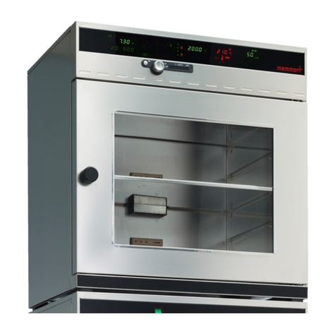
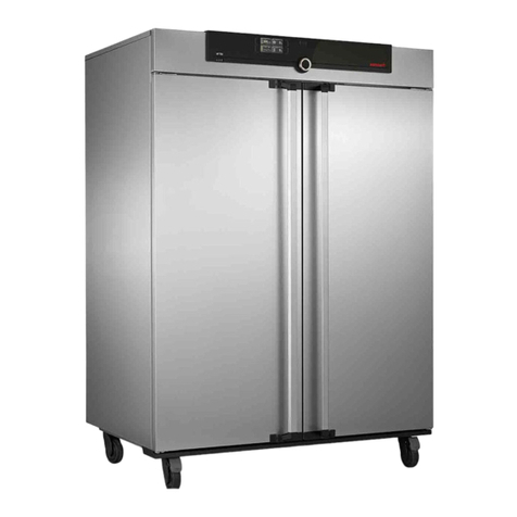
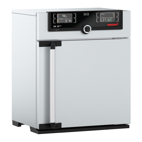
Memmert VO Series User manual

www.memmert.com |www.atmosafe .net
100% ATMOSAFE. MADE IN GERMANY.
OPERATING MANUAL
VACUUM OVEN VO
VO

Manufacturer and customer service
MEMMERT GmbH + Co. KG
Willi-Memmert-Straße 90-96
91186 Büchenbach
Germany
Phone: +49 (0)9122 925-0
Fax: +49 (0)9122 14585
E-mail: [email protected]
Internet: www.memmert.com
Customer service:
Service hotline: +49 (0)9171 9792 911
Service fax: +49 (0)9171 9792 979
E-mail: [email protected]
When calling for service enquiries, please state the appliance number given on the name-
plate (see page 15).
Shipping address for repairs:
Memmert GmbH + Co. KG
Customer service
Willi-Memmert-Str. 90-96
DE-91186 Büchenbach
Germany
Please contact our customer service department before sending appliances for repair or
before returning equipment, or the shipment may be refused.
© 2018 MEMMERT GmbH + Co. KG
D39374 | Date 08/2018
Subject to change without notice

D39374 | Date 08/2018 3
About this manual
About this manual
Purpose and target audience
This manual describes the assembly, function, transport, putting into operation, opera-
tion, troubleshooting, maintenance and decommissioning/disposal of the vacuum oven
VO. It is intended for use by trained personnel of the owner, who have the task of oper-
ating and/or maintaining the respective appliance.
If you are asked to work on the appliance, read this manual carefully before starting. Fa-
miliarise yourself with the safety regulations. Only perform work that is described in this
manual. If there is something you do not understand, or certain information is missing,
ask your manager or contact the manufacturer. Do not do anything without authorisa-
tion.
Versions
The appliances are available in different configurations and sizes. If specific equipment
features or functions are available only for certain configurations, this is indicated at the
relevant points in this manual.
The functions described in this manual refer to the latest firmware version.
Due to individual configurations and sizes, illustrations in this manual may be slightly dif-
ferent to the actual appearance. Function and operation are identical.
Other documents to be observed:
►Observe the relevant manual when operating the appliance with MEMMERT
AtmoCONTROL computer software. Click on “Help” on the AtmoCONTROL menu bar
to open the AtmoCONTROL software manual.
►Please refer to the separate service manual for service and repair work (see page
63).
Storage and resale
This operating manual belongs with the appliance and should always be stored where
persons working on the appliance have access to it. It is the owner's responsibility to
ensure that persons who are working on or are going to work on the appliance know
where to find the operating manual. We recommend that it is always stored in a protect-
ed location close to the appliance. Make sure that the operating manual is not damaged
by heat or humidity. If the appliance is resold or transported and then set up again at a
different location, the operating manual must remain with it.
For the current version of this operating manual in PDF format, please go to http://www.
memmert.com/en/service/downloads/user-manual/ .

4 D39374 | Date 08/2018
Contents
Contents
1. For your safety 6
1.1 Terms and signs used........................................................................................................... 6
1.2 Product safety and dangers ................................................................................................ 6
1.3 Requirements of the operating personnel.......................................................................... 7
1.4 Responsibility of the owner................................................................................................. 8
1.5 Changes and alterations...................................................................................................... 8
1.6 Behaviour in case of malfunctions and irregularities.......................................................... 8
1.7 Switching off the appliance in an emergency .................................................................... 8
2. Design and description 9
2.1 Design.................................................................................................................................. 9
2.2 Intended use...................................................................................................................... 10
2.3 Function............................................................................................................................. 10
2.4 Materials used ................................................................................................................... 12
2.5 Electrical equipment.......................................................................................................... 12
2.6 Connections and interfaces............................................................................................... 12
2.7 Designation (nameplate)................................................................................................... 15
2.8 Technical data .................................................................................................................... 16
2.9 Declaration of conformity ................................................................................................. 17
2.10 Ambient conditions........................................................................................................... 18
2.11 Scope of delivery ............................................................................................................... 18
2.12 Optional accessories.......................................................................................................... 18
3. Delivery, transport and setting up 19
3.1 Delivery .............................................................................................................................. 20
3.2 Transport............................................................................................................................ 20
3.3 Unpacking ......................................................................................................................... 20
3.4 Storage after delivery ........................................................................................................ 20
3.5 Setting up .......................................................................................................................... 21
4. Putting into operation 25
4.1 Connecting the appliance .................................................................................................25
4.2 Install suction..................................................................................................................... 27
4.3 Insert thermoshelves ......................................................................................................... 28
4.4 Switching on...................................................................................................................... 29
5. Operation and control 30
5.1 Operating personnel.......................................................................................................... 30
5.2 Opening the door.............................................................................................................. 30
5.3 Operating the appliance.................................................................................................... 31
5.4 Temperature monitoring .................................................................................................. 37
5.5 Pressure monitoring .......................................................................................................... 41
5.6 Graph................................................................................................................................. 42
5.7 Ending operation............................................................................................................... 43
6. Malfunctions, warning and error messages 44
6.1 Warning messages of the monitoring function................................................................ 44
6.2 Malfunctions, operating problems and appliance errors ................................................ 45
6.3 Power failure...................................................................................................................... 47
D39374 | Date 08/2018 5
Contents
7. Menu mode 48
7.1 Overview............................................................................................................................ 48
7.2 Basic operation in menu mode using the example of language selection....................... 49
7.3 Setup.................................................................................................................................. 50
7.4 Date and time....................................................................................................................53
7.5 Calibration ......................................................................................................................... 54
7.6 Program............................................................................................................................. 59
7.7 Sounds............................................................................................................................... 60
7.8 Logging.............................................................................................................................. 61
7.9 USER ID.............................................................................................................................. 62
8. Maintenance and Servicing 63
8.1 Cleaning............................................................................................................................. 63
8.2 Regular maintenance.........................................................................................................63
8.3 Repairs and Service............................................................................................................ 63
9. Storage and disposal 64
9.1 Storage .............................................................................................................................. 64
9.2 Disposal ............................................................................................................................. 64
Index 65

6 D39374 | Date 08/2018
For your safety
1. For your safety
1.1 Terms and signs used
In this manual and on the appliance itself, certain common terms and signs are used to
warn you of possible dangers or to give you hints that are important in avoiding injury or
damage. Observe and follow these notes and regulations to avoid accidents and dam-
age. These terms and signs are explained below.
1.1.1 Terms used
WARNING
Warns of a dangerous situation that might lead to death or
serious injuries
CAUTION
Warns of a dangerous situation that might lead to moderate
or minor injuries
NOTICE
Warns of material damage
1.1.2 Signs used
Signs used
Danger of elec-
trocution
Danger of
explosion
Dangerous
gases/vapours
Danger of burns Danger of
toppling over
Gas bottles Disconnect the
mains plug
Wear gloves Observe informa-
tion in separate
manual
1.2 Product safety and dangers
The appliances described in this manual are technically sophisticated, manufactured
using high-quality materials and subject to many hours of testing in the factory. They
reflect the state of the art and comply with recognised technical safety regulations. How-
ever, there are still risks involved, even when the appliances are used as intended. These
are described below.

D39374 | Date 08/2018 7
For your safety
WARNING
After removing covers, live parts may be exposed. Touching these
can lead to an electric shock. Disconnect the mains plug before
removing any covers. Work on the electrical system must only be
performed by qualified electricians.
WARNING
Toxic gases or vapours may be produced in certain applications.
These can escape from the vacuum pump into the room. This can
injure people nearby.
The appliance may only be used for such applications if a suction is
attached to the vacuum pump used, which reliably keeps toxic gases
or vapours away from people. Observe the respective national regu-
lations for occupational safety and environmental protection.
WARNING
Depending on operation, the surfaces in the interior of the appliance
and the chamber load may still be very hot after the appliance is
switched off. Touching these surfaces can cause burns. Wear heat-
resistant protective gloves or wait until the appliance cools down
before touching.
WARNING
Gas bottles may burst or explode at high temperatures. Keep the
gas bottles away from open flames. Store gas bottles below 50 °C
and ensure that the location is always well ventilated. Prevent water
from penetrating as well as backflow into the gas bottles. It is es-
sential that you read the safety notes and instructions of the gas
supplier.
1.3 Requirements of the operating personnel
The appliance may only be operated and maintained by persons who are of legal age and
have been instructed accordingly. Personnel who are to be trained, instructed or who
are undergoing general training may only work with the appliance under the continuous
supervision of an experienced person.
Repairs may only be performed by qualified electricians. The regulations in the separate
service manual must be observed.

8 D39374 | Date 08/2018
For your safety
1.4 Responsibility of the owner
The owner of the appliance
►is responsible for the flawless condition of the appliance and for it being operated in
accordance with its intended use (see page 8);
►is responsible for ensuring that persons who are to operate or service the appliance
are qualified to do this, have been instructed accordingly and are familiar with the
operating instructions at hand;
►must know about the applicable guidelines, requirements and operational safety
regulations, and train staff accordingly;
►is responsible for ensuring that unauthorised persons have no access to the appli-
ance;
►is responsible for attaching a suction to the vacuum pump used if toxic gases or
vapours may arise as a result of the process;
►is responsible for ensuring that the maintenance plan is adhered to and that mainte-
nance work is carried out properly (see page 63);
►has to ensure that the appliance and its surroundings are kept clean and tidy, for
example through corresponding instructions and inspections;
►is responsible for ensuring that personal protective clothing is worn by operating
personnel, e.g. work clothes, safety shoes and protective gloves.
1.5 Changes and alterations
No unauthorised changes or alterations may be made to the appliance. No parts may be
added or inserted which have not been approved by the manufacturer.
Unauthorised changes or alterations result in the CE declaration of conformity losing its
validity, and the appliance may no longer be operated.
The manufacturer is not liable for any damage, danger or injuries that result from un-
authorised changes or alterations, or from non-compliance with the provisions in this
manual.
1.6 Behaviour in case of malfunctions and irregularities
The appliance may only be used in a flawless condition. If you as the operator notice ir-
regularities, malfunctions or damage, immediately take the appliance out of service and
inform your superior.
You can find information on troubleshooting from page 44.
1.7 Switching off the appliance in an emergency
Press the main switch on the ControlCOCKPIT
(Fig. 1) and disconnect the power plug.
This disconnects the appliance from the
power supply at all poles. ON
O
O
ON
N
N
N
O
O
N
O
Fig. 1
Switch off the appliance by pressing the
main switch

D39374 | Date 08/2018 9
Design and description
2. Design and description
2.1 Design
1
2
3
4
5
Fig. 2 Design
1 ControlCOCKPIT with capacitive function keys and LCD displays (see page 32)
2 Vacuum oven VO
3 Thermoshelves
4 Main switch Pump module
5 Pump module

10 D39374 | Date 08/2018
Design and description
2.2 Intended use
Vacuum ovens VO are used for drying, testing, moisture determination, airtight storage,
curing and degassing of substances or materials under vacuum, which are used in the
procedures and specifications described in the operating instructions.
The appliance is not explosion-proof. The use of explosive substances or materials is abu-
sive and can lead to hazards or damage. The appliance may only be loaded with materi-
als and substances which cannot form any explosive vapours at the set temperature and
which cannot explode, burst or ignite.
2.3 Function
The devices of the VO series (Fig. 3 1) can generate a vacuum in working chamber3 in
conjunction with Memmert pump module 2 or another suitable vacuum pump. The
vacuum inlet on the back of appliance 4evacuates the working chamber through the
pump.
Optionally, the working chamber can be supplied with inert gas through a connection on
the rear of the appliance 56.
For temperature control thermal plates with electronic contacts are inserted into tube 7.
If the electronic contacts are connected to the connections in rear panel 8, the ther-
moshelves can emit heat by direct contact with the load.
If toxic gases or vapours may be produced in the intended application, these must be
safely discharged by the customer via an extraction system and cleaned if necessary 9.

D39374 | Date 08/2018 11
Design and description
1
3
2
5
4
6
9
7 8
0
0
N
2
He
Ne
Ar
Kr
Xe
9
9
9
9
9
Fig. 3 Function of vacuum ovens VO in conjunction with a pump module
1 VO
2 Vacuum pump
3 VO working chamber
4 Hose connection between VO and vacuum pump
5 Gas cylinder (inert gas, optional)
6 Inert gas supply
7 Thermoshelves
8 Contacting the Thermoshelves in the appliance
9 Suction (required if toxic gases or vapours may be produced as a result of the process)
10 Wall mounting (tilt protection, see page 23)

12 D39374 | Date 08/2018
Design and description
2.4 Materials used
Component Materials
Housing Stainless steel (W.St.Nr. 1.4016)
Piping Stainless steel (W.St.Nr. 1.4571)
Interior Stainless steel (W.St.Nr. 1.4404), which stands out
through its high stability, optimal hygienic proper-
ties and corrosion-resistance towards many (but not
all!) chemical compounds (caution for example with
chlorine compounds).
Thermoshelves Aluminium. The vulcanised heating mat covered with
stainless steel on the underside of the thermoshelf is
made of silicone.
Plug connection of thermoshelf
and rear flange socket
Ryton R4 (GF-PPS plastic) or PEEK-GF30
Seals in solenoid valves and
flange sockets
Fluorocarbon FKM / FPM (Viton)
Door seal Silicone
A resistance table for all these materials can be requested from the company MEMMERT.
2.5 Electrical equipment
►Operating voltage and current consumption: See nameplate
►Protection class I, i.e. operating insulation with PE conductor in accordance with EN
61010
►Protection class IP 20 acc. to EN 60529
►Interference suppression acc. to EN 55011 class B
►Appliance fuse: Safety fuse 250 V/15 A, quick-blow
►The temperature sensor is equipped with a 100 mA miniature fuse.
2.6 Connections and interfaces
2.6.1 Electrical connection
This appliance is intended for operation on an electrical power system with a system
impedance Zmax of a maximum of 0.292 ohm at the point of transfer (service line). The
operator must ensure that the appliance is operated only on an electrical power system
that meets these requirements. If necessary, you can ask your local energy supply com-
pany what the system impedance is.
Observe the country-specific regulations when making connections (e.g. in Germany DIN
VDE 0100 with earth leakage circuit breaker).

D39374 | Date 08/2018 13
Design and description
2.6.2 Fresh air, inert gas and vacuum connection
At the left rear post are the
connections for the inlet of fresh
air or inert gas (optional) and the
connection for the vacuum
pump (DN 16 KF, Fig. 4 and Fig.
5).
Fresh air
The fresh air connection has two
functions. On the one hand,
the device is ventilated via the
connection and thus the nega-
tive pressure is adapted to the
atmospheric pressure. On the
other hand, the connection is
opened by the appliance con-
troller for a very short time in
order to fine-tune the negative
pressure.
Inert gas (optional)
By applying inert gas to the working chamber, a protective atmosphere can be created
which protects the load from contact with ambient air.
Vacuum
The vacuum connection is designed as an ISO-KF connection of size DN 16. Either the
supplied pump module or another suitable external vacuum pump are connected to it.
When using an external vacuum pump, make sure that the pump is suitable for the ma-
terial being fed and the desired process.
Required parameters of a suitable pump:
►Pumping speed > 30 Nl/min
►Final vacuum ≤3 mbar
►chemical-resistant version
►temperature resistant (exhaust gas temperature like working temperature)
1
2
3
Fig. 4 Connections
on the back of VO 49
Premium and VO 101
Premium appliances
1 Fresh air supply
2 Inert gas connection
3 Vacuum pump con-
nection
1
2
3
Fig. 5 Connections
on the back of VO 29
Premium units and all
standard appliances
1 without function
(blanking plug)
2 Fresh air supply
3 Vacuum pump con-
nection

14 D39374 | Date 08/2018
Design and description
2.6.3 Communication interfaces
The communication interfaces are intended for appliances which meet the requirements
of IEC 60950-1.
USB interface
The appliance is fitted by default with a
USB port in accordance with the USB speci-
fication. This way, you can
►transfer software stored on a USB stor-
age medium to the appliance (see page
59).
►export protocol logs from the appliance
to a USB storage medium (see page
61).
►transfer user ID data stored on a USB storage medium to the appliance (see page
62).
The USB port is located on the right of the ControlCOCKPIT (Fig. 6).
Ethernet interface
The appliance can be connected to a network via the
Ethernet interface, so that you can transfer
programmes created with the AtmoCONTROL
software to the appliance and read out protocols.
The Ethernet interface is located on the rear of
the appliance (Fig. 7).
For identification purposes, each appliance con-
nected must have its own unique IP address.
Configuration of the IP address is described on
page 50.
You will find a description of how to transfer programs via Ethernet in the
enclosed AtmoCONTROL manual.
The appliance can be directly connected to a computer / laptop using an optional USB to
Ethernet converter (see Scope of delivery on page 18).
2.6.4 Switching output for external vacuum pump purge valve and pump control
The 8-pin switching output on the rear right post
(Fig. 8) is used to control the vacuum pump of
the optional pump module (PM) through the
vacuum oven (VO). The switching output is
backwards-compatible with the 3-pole contact of
older pump modules. For this purpose, plug the
3-pole cable into the 8-pole contact.
Fig. 6 USB interface
Fig. 7 Ethernet interface
Fig. 8 Switching output

D39374 | Date 08/2018 15
Design and description
Vacuum pump rinsing valve
When drying feed materials with a high moisture content, the pump capacity may de-
crease during prolonged operation due to condensation in the pump heads. The dia-
phragms are blown free by briefly flushing the pump heads with fresh air.
This improves the efficiency of the drying process. In combination with the optionally
available pump modules PM29, PM49 and PM101, this cyclical flushing takes place auto-
matically when the pump output decreases. The drying process is thus faster and more
energy-saving and the pump is protected.
Speed control and switch-off of the vacuum pump
After completing a drying program or after a long period of operation without a vacuum
request from the controller, the vacuum pump installed in the pump module (PM) is
switched off via the control line. The demand-controlled pump speed control saves
energy, is low-noise and increases the service life of the vacuum pump by protecting the
pump diaphragms.
Note: A control signal switches off the pump module (PM) installed in the optional
vacuum pump. The operating light in the main switch of the pump module also lights up
if the vacuum pump has been switched off via the control line.
2.7 Designation (nameplate)
The nameplate (Fig. 9) provides information about the appliance model, manufacturer
and technical data. It is attached to the front of the appliance, on the right behind the
door.
Typ: V0101 F.-Nr.: S618.0001
230 V~ 10.5 A 50/60 Hz 2400 W
DIN12880-Kl.3.1 Nenntemp.: 200 °C
1
2
3
4
5
6
10
8
9
7
Fig. 9 Nameplate (example)
1 Type designation
2 Operating voltage
3 Applicable standard
4 Protection type
5 CE conformity
6 Address of manufacturer
7 Disposal note
8 Temperature range
9 Connection / power ratings
10 Appliance number

16 D39374 | Date 08/2018
Design and description
2.8 Technical data
Appliance size 29 49 101
A
pp
liance width D1[mm] 550 550 710
Appliance height E1[mm] 600 680 760
Appliance depth F1[mm] 400 480 550
De
p
th of door lock [mm] 38
Chamber width A1[mm] 385 385 545
Chamber height B1[mm] 305 385 465
Chamber depth C1[mm] 250 330 400
Base
Width G [mm] 529 529 689
Height H [mm] 450 290 130
Depth I [mm] 383 463 533
Chamber volume [litres] 29 49 101
Weight [kg] 62 74 100
Power [W] 820 2020 2420
Current consumption [A] 230 V, 50/60 Hz 3.6 8.8 10.5
max. number of ther-
moshelves
Standard 1 2 2
Premium 2 4 4
max. load per Thermoshelf [kg] 20
max. load per appliance [kg] 60 80 150
Temperature
Adjustment range 20 °C to 200 °C
Adjustment precision 0.1 K
Operating temperature range From 5° C to 200° C (including ambient
tem
p
erature)
Pressure
Adjustment range 5 mbar - 1100 mbar
Adjustment precision 1 mbar
Leak rate ≤0.5 x 10⁻² mbar 1/sec
1See Fig. 10
2The minimum temperature depends on the outdoor temperature (see ambiant conditions on page
18).

D39374 | Date 08/2018 17
Design and description
D
H
E E
12
12
G
40
80 80
A
I
40
200
38
F
200
80
80
B
200
C
x
Fig. 10 Dimensions
2.9 Declaration of conformity
You can download the EC declaration of conformity of the appliance online:
English: http://www.memmert.com/en/service/downloads/ce-statement/
German: http://www.memmert.com/de/service/downloads/eg-konformitaetserklaerung/

18 D39374 | Date 08/2018
Design and description
2.10 Ambient conditions
►The appliance may only be used in enclosed areas and under the following ambient
conditions:
Ambient temperature +5 ºC to +40 ºC
Humidity rh max. 80 % non-condensing
Overvoltage category II
Pollution degree 2
Altitude of installation max. 2,000 m above sea level
►The appliance may not be used in areas where there is a risk of explosion. The ambi-
ent air must not contain any explosive dusts, gases, vapours or gas-air mixtures. The
appliance is not explosion-proof.
►Heavy dust production or aggressive vapours in the vicinity of the appliance could
lead to sedimentation in the interior and, as a consequence, could result in short
circuits or damage to electrical parts. For this reason, sufficient measures to prevent
large clouds of dust or aggressive vapours from developing should be taken.
2.11 Scope of delivery
►Power cable
►Tilt protection
►Thermoshelves (Standard and Premium VO 29 1 shelf; Premium VO 49 and VO 101 2
shelves)
►USB storage medium with software and AtmoCONTROL manual
►the operating instructions at hand
►Calibration certificate
2.12 Optional accessories
With an Ethernet-USB converter (Fig. 11) it is
possible to connect the Ethernet port of
the appliance (see page 14) to the USB
port of a PC/laptop.
Fig. 11 USB to Ethernet converter

D39374 | Date 08/2018 19
Delivery, transport and setting up
3. Delivery, transport and setting up
WARNING
The appliance may only be lifted and placed with a special lifting de-
vice. This lifting device must be used for lifting and carrying. Without
a lifting device there is a great risk of injury!
The lifting device can be purchased from the dealer. Either the dealer sends the device to
the customer or the dealer assembles the appliances himself with the device.
To set up appliances of the sizes 29 and 49,
at least two persons, for appliances of size
101, four persons are needed.
To lift the appliance, guide the lifting device
under the appliance from both sides (Fig. 12)
and lift the appliance.
Fig. 12 Lifting equipment
WARNING
There is a risk of tipping when stacking on a pump module. Do not
move stacked device combinations.
29 49 101

20 D39374 | Date 08/2018
Delivery, transport and setting up
3.1 Delivery
The appliance is packed in cardboard and is delivered on a wooden palette.
3.2 Transport
The appliance can be transported in three ways:
►With a forklift truck; move the forks of the truck entirely under the pallet.
►On a manual pallet jack
►(only with the lifting device)
3.3 Unpacking
To avoid damage, do not unpack the appliance until you reach the installation site.
Remove the cardboard packaging by pulling it upwards or carefully cutting along an
edge.
3.3.1 Checking for completeness and transport damage
►Check the delivery note to ensure that the scope of delivery is complete.
►Check the appliance for damage.
If you notice deviations from the delivery note, damage or irregularities, do not put the
appliance into operation but inform the haulage company and the manufacturer.
3.3.2 Remove the transportation lock
Remove the transportation lock. It is located between the door hinge, door and frame
and has to be removed after opening the door.
3.3.3 Disposing of packaging material
Dispose of the packaging material (cardboard, wood, foil) in accordance with the appli-
cable disposal regulations for the respective material in your country.
3.4 Storage after delivery
If the appliance is first to be stored after delivery: Read the storage conditions from page
64.
This manual suits for next models
3
Table of contents
Other Memmert Oven manuals

Memmert
Memmert UNE 200 User manual

Memmert
Memmert UFTS User manual

Memmert
Memmert SF Series User manual

Memmert
Memmert VO200 User manual

Memmert
Memmert SE 200 User manual

Memmert
Memmert BASIC Operating instructions

Memmert
Memmert UE 200 User manual

Memmert
Memmert UN User manual

Memmert
Memmert UF450plus User manual

Memmert
Memmert UN Series User manual
Popular Oven manuals by other brands

Siemens
Siemens HB213AB 0 Series User manual and installation instructions

Fulgor Milano
Fulgor Milano F7SP24S1 Use & care manual

Grundig
Grundig GEBD19300DX user manual

Siemens
Siemens HB772G1 1 Series User manual and installation instructions

Zanussi
Zanussi ZOD35712B user manual

Bosch
Bosch HBC86P753B instruction manual