Memmert VO200 User manual

PERFECT
VO
set
off
on push card
PRINT SETUP
loop
t3
t4
t2
t1
on
off
Mo Tu We Th Fr Sa Su
3
4
2
1
STERI DEFRO
°C °C rh
mb
%CO
mb
2
IN 1 IN 2 OUT IN 1 IN 2 OUT
MIN
AUTO
MAX
VO
page 1
Vacuum Drying Oven
VO200 / VO400 / VO500
Operating Instructions
Pump Module
PM200 / PM400 / PM500

PERFECT page 2
1. Contents
1. Contents......................................................................................................................................................................2
2. General notes and safety notes ....................................................................................................................................4
2.1 Material quality from MEMMERT:.......................................................................................................................4
2.2 Transport ...........................................................................................................................................................5
2.3 Initial start-up....................................................................................................................................................5
2.4 Oven load..........................................................................................................................................................5
2.5 Safety check ......................................................................................................................................................5
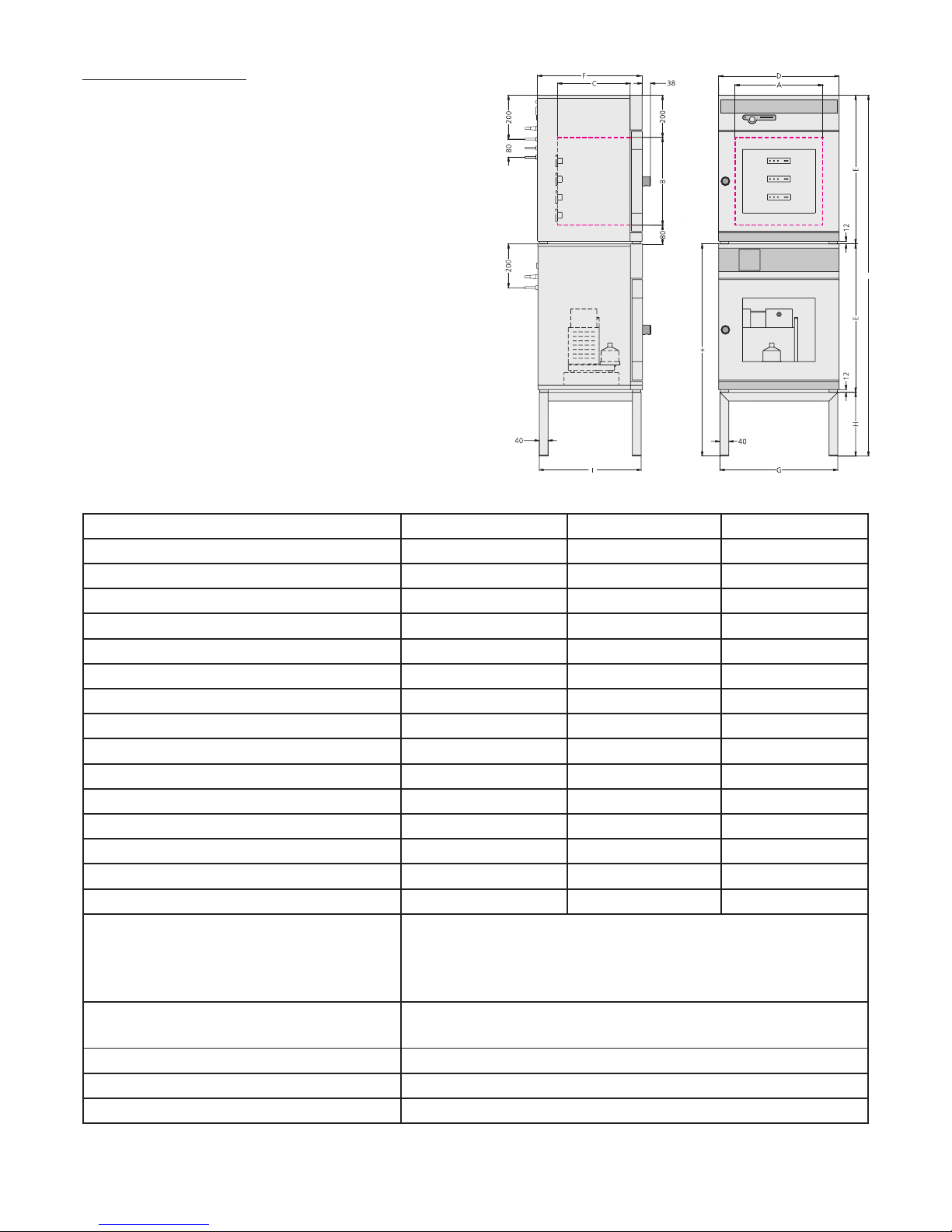
3. Technical data..............................................................................................................................................................6
3.1 Standard equipment of VO-ovens ......................................................................................................................7
3.2 Electrical equipment ..........................................................................................................................................8
3.3 External connection ...........................................................................................................................................8
4. Installation facilities (accessories)..................................................................................................................................9
4.1 Subframe...........................................................................................................................................................9
4.2 Stackable version ...............................................................................................................................................9
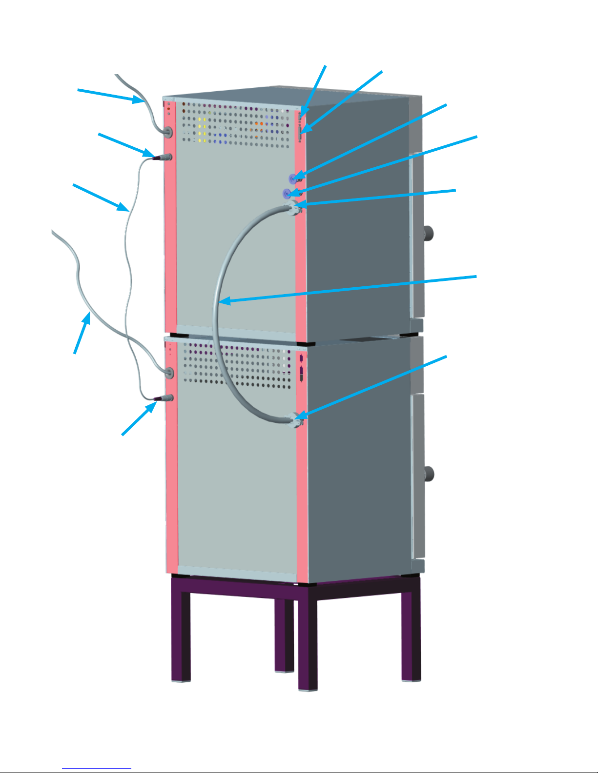
5. Oven construction and connections............................................................................................................................10
6. Starting up ................................................................................................................................................................12
7. Switching output for external vacuum pump purge valve and pump control...............................................................13
7.1 Vacuum pump purge valve ..............................................................................................................................13
7.2 Demand-controlled vacuum pump shut-down .................................................................................................13
8. Loading and Inertgas .................................................................................................................................................14
9. Guidelines for evaporating liquids in Memmert-vacuum ovens....................................................................................15
10. Controls and indications.............................................................................................................................................16
11. Operating the door....................................................................................................................................................16
12. Switching on .............................................................................................................................................................16
13. Setting the temperature.............................................................................................................................................16
14. Quick venting function...............................................................................................................................................17
15. Status indication for the heating levels .......................................................................................................................17
16. Selecting the operating mode ....................................................................................................................................18
17. Setting the parameters............................................................................................................................................... 18
18. Normal operation ............................................................................................................................................19
Setting example “Normal operation“..........................................................................................................................20
19. Weekly programmer ........................................................................................................................................21
Programming example “Weekly programmer“............................................................................................................22
20. Programme operation ......................................................................................................................................23
20.1 Closure commands for ramp segments ............................................................................................................25
Programming example programme operation ............................................................................................................26
21. Printer
PRINT .............................................................................................................................................................29
22. Basic oven settings SETUP ...........................................................................................................................................30
22.1 Real-time clock ................................................................................................................................................31

PERFECTpage 3
23. Temperature monitor and protection devices..............................................................................................................32
23.1 Mechanical temperature monitor: temperature limiter (TB)...............................................................................32
23.2 Electronic temperature monitor........................................................................................................................33
23.2.1 Overtemperature protection MAX ................................................................................................................33
23.2.2 Undertemperature protection MIN ..............................................................................................................33
23.2.3 Adjustable temperature monitor (TWW) Protection Class 3.1 to DIN 12 880................................................... 34
23.2.4 Adjustable temperature limiter (TWB) Protection Class 2 to DIN 12 880..........................................................34
23.2.5 Automatic temperature monitor (ASF) AUTO .............................................................................................35
24. Calibration.................................................................................................................................................................38
24.1 Calibration-temperature...................................................................................................................................38
24.2 Calibration-pressure (vacuum)..........................................................................................................................40
25. Communication interface for the PC...........................................................................................................................42
25.1 Communication interface RS232C ....................................................................................................................42
25.2 Bus interface RS485 .........................................................................................................................................43
26. Report memory..........................................................................................................................................................44
26.1 Reading the report memory .............................................................................................................................44
26.2 Reading the report memory into the PC via RS232C..........................................................................................44
26.3 Printing the report memory from the oven .......................................................................................................44
27. Memory card: MEMoryCardXL ...................................................................................................................................45
27.1 Programming the MEMoryCardXL from the oven .............................................................................................45
27.2 Programming the MEMoryCardXL from a PC with the oven..............................................................................45
27.3 Programming the MEMoryCardXL from a PC using the read-write unit .............................................................45
27.4 Documentation on memory card MEMoryCardXL.............................................................................................46
28. USER-IDcard (available as optional extra)....................................................................................................................47
29. Cleaning ....................................................................................................................................................................48
30. Maintenance..............................................................................................................................................................48
31. Door seal ...................................................................................................................................................................49
32. Error messages...........................................................................................................................................................50
33. Supply failure.............................................................................................................................................................50
34. CE Conformity Declaration .........................................................................................................................................51
35. Address and customer service .................................................................................................................................... 52
36. Index .........................................................................................................................................................................53

PERFECT page 4
This mark in the Operating Instructions means:
Watch out
Important Note!
2. General notes and safety notes
You have purchased a technically fully proven product which has been produced in Germany with the use
of high-grade materials and the application of the latest manufacturing techniques; it has been factory
tested for many hours.
In addition we guarantee the supply of spare parts over 10 years.
This mark on the product means:
Note Operating Instructions
Warning – oven hot when operating!
Observation of the Operating Instructions is necessary for faultless
operation and for any possible claims under warranty. If these
Instructions are disregarded, all claims under warranty, guarantee and
indemnification are excluded!
The right to technical modifications is reserved.
Dimensional details are not binding.
2.1 Material quality from MEMMERT:
External casing: stainless steel (V2A, Mat.Ref. 1.4301)
Piping: stainless steel (V4A, Mat.Ref. 1.4571)
Working space: stainless steel (V4A, Mat.Ref. 1.4404) featuring high stability, optimal hygienic
properties, and corrosion resistance against many (not all!) chemical compounds (warning
against chlorine compounds, for example).
Thermotrays: stainless steel (Mat. Ref. 1.4404 = V4A). The heating mat is vulcanised to the
underside of the thermotray and covered with stainless steel; it consists of Silicone rubber.
Connector between thermotray and electrical socket in rear wall: Ryton R4 (GF PPS plastics)
and PEEK-GF30
Seals in solenoid valves and electrical sockets: fluoride rubber FKM/FPM (Viton)
Door seal: Silicone rubber
The load for the vacuum drying oven must be carefully evaluated for its chemical compatibility with the
above materials.
A table listing about the compatibility of all these materials can be requested from MEMMERT.
•
•
•
•
•
•
•

PERFECTpage 5
2.2 Transport
Always use gloves!
If the oven has to be carried, at least 2 persons are required to transport it.
2.3 Initial start-up
When the oven is started up for the first time, it should be supervised continuously until steady conditions
have been reached.
2.4 Oven load
Full consideration must be given to the physical and chemical properties of your load (e.g. combustion
temperature etc.) in order to prevent serious damage to load, oven and surroundings.
Please note that the Memmert ovens described here are not explosionproof (they do not conform to the
Industrial Association Specification VBG 24) and are therefore not suitable for drying, evaporating and
burning-in of paints, enamels or similar materials whose solvents may produce an inflammable mixture
with air. There must be no possibility of the formation of inflammable gas/air mixtures either within the
oven chamber or in the immediate surroundings of the equipment.
Large amounts of dust or corrosive fumes inside the oven chamber or in the surroundings of the equipment
may produce deposits within the oven and lead to short-circuits or damage the electronics. It is therefore
important that adequate precautions are taken against excessive dust or corrosive fumes.
In order to ensure proper air circulation inside the chamber, there must be sufficient spacing of the load
inside the oven. Do not place any load on the floor, against the side walls or underneath the ceiling of the
chamber (heating ribs). In order to ensure optimum air circulation the shelves must be so inserted that the
air spacings between door, shelf and rear chamber wall are approximately equal.
The maximum number and the loading of the shelves can be found in the table in the Section „Technical Data“.
2.5 Safety check
The door and the security glass panels must be checked regularly for scratches or damage. No vacuum
must be applied to the oven if there is any damage.

PERFECT page 6
3. Technical data
Model 200 400 500
Chamber width A [mm] 385 385 545
Chamber height B [mm] 305 385 465
Chamber depth C [mm] 250 330 400
Oven width D [mm] 550 550 710
Oven height E [mm] 600 680 760
Oven depth F [mm] 400 480 550
Width G [mm] 529 529 689
Height H [mm] 450 290 130
Depth I [mm] 383 463 533
Chamber volume [litre] 29 49 101
Weight [kg] 58 82 120
Power [W] 1200 2000 2400
Max. number of shelves 3 4 4
Max. load per shelf [kg] 20 20 20
Max. load per oven [kg] 40 60 60
Ambient conditions Ambient temperature 5°C to 40°C
rH 80% max., no condensation
Overvoltage category: II
Contamination level: 2
Setpoint temperature range 20°C to 200°C
10mbar - 1100mbar
Setting accuracy 0.5°C / 1mbar
Working temperature range From 5°C above ambient temperature up to 200°C
Leakage rate max. 0.5 x 10⁻² mbar 1/sec

PERFECTpage 7
3.1 Standard equipment of VO-ovens
Electronic fuzzy-supported PID process controller with permanent power matching and time-saving
auto-diagnostic system for rapid fault finding (see Section: „Error messages“)
Language selection
Alphanumerical text display
Internal report memory 1024kB for storing actual temperature, setpoint temperature, pressure
and error states with time stamp
Control of oven and documentation of actual values on MEMoryCardXL
Programme sequence control for up to 40 ramp segments
Vacuum control for digital operation of the built-in solenoid valves
Control output 24 Volt for purging and to switch off the external vacuum pump
Selectable inlet valves for fresh air and inert gas
Integral weekly programmer with group function (e.g. all workdays)
Recessing push/turn control for simple operation of oven
Visual alarm indication
Built-in sounder as alarm on overlimit, as audible signal at programme end, and to acknowledge
input (key click)
Digital monitor controller for overtemperature, undertemperature, and as automatically setpoint-
following monitor (ASF)
Mechanical temperature limiter (TB Class 1)
Monitor relay to switch off heating in case of fault
Each thermotray has a separate Pt100 DIN Class A temperature sensor for temperature
measurement and can be removed individually
Convenient integral 3-point temperature calibration
Temperature-dependent control panel venting
Parallel printer interface (PCL3 compatible)
Serial RS-232C interface for computer-supported temperature programmes and for reading the
internal report memory
MEMMERT software “Celsius 2005“ for remote operation of oven via a PC and for reading the
report memory inside the controller
A pre-formatted blank MEMoryCardXL with 32 kB storage capacity, reprogrammable for up to 40
ramp segments and additionally 270 hours report memory at 1 minute intervals
Special equipment (to be ordered separately as accessories): subframe, pump module, cable
RS232C to DIN 12 900-1, external card reader for MEMoryCardXL for connection to the PC RS232C
interface, 25-way printer cable (parallel, screened)
•
•
•
•
•
•
•
•
•
•
•
•
•
•
•
•
•
•
•
•
•
•
•
•

PERFECT page 8
Do not place the oven on a readily inflammable support surface!
WARNING! Always pull out the supply plug before
opening the oven cover!
3.2 Electrical equipment
Operating voltage see label 50/60 Hz
Current rating see label
Protection Class 1, i.e. operating isolation with ground connection to EN 61 010
Protection IP20 to EN 60 529
Interference suppression to EN55011 Class B
Oven protected by a fuse 250V/15A fast blow
Controller protected by a 100 mA fuse (200 mA on 115 V)
When connecting a MEMMERT oven to the electrical supply you have to observe any local
regulations which apply (e.g. in Germany DIN VDE 0100 with FI protection circuit)
This product is intended to operate on a supply network with a system impedance Zmax at the
transfer point (building connection) of 0.292 Ohm max. The user has to ensure that the product is
only operated on an electrical supply network which meets these requirements. If necessary, details
of the system impedance can be obtained from the local electricity supply authority.
Note:
Any work involving opening up the oven must only be carried out by a suitably qualified
electrician!
3.3 External connection
Equipment connected to the external connections must have interfaces which meet the requirements for
safe low voltage (e.g. PC, printer).
•
•
•
•
•
•
•
•

PERFECTpage 9
4. Installation facilities (accessories)
The oven can be placed on the floor or on a
bench (working surface). It is important that
the oven is set up accurately horizontally; the
door may have to be adjusted (see Section:
„Maintenance“)
The spacing from the back of the oven to the
wall should be at least 15 cm. The spacing to
the ceiling must not be less than 20 cm and
that at the side to the wall not less than 8 cm.
Generally it is essential to have adequate air
ventilation around the oven.
Information on accessories will be found in our leaflet or on our internet page www.memmert.com.
Please note the installation instructions for our accessories.
4.1 Subframe
Oven models 200 to 500 can be mounted on a subframe (accessory)
4.2 Stackable version
Two ovens of the same model size can be stacked on each other. Note that the oven
with the lower working temperature must always be placed at the bottom.
Foot locators (accessory) have to be fitted on the bottom oven.
Take off cover of bottom oven
Place drill jig (supplied with foot locators) into the inverted cover at the
back
Mark holes and drill 4.2 mm dia.
Screw the foot locators to the top of the cover using the screws and nuts
supplied
Re-fit the cover
•
•
•
•
•
15 cm
min.
8 cm
min.
8 cm
min.
20 cm
min.
Oven on the
floor
Oven on
subframe
Oven on pump
module
Oven on pump
module and
subframe

PERFECT
6
3
4
2
7
1
5
10
8
9
12
11
page 10
5. Oven construction and connections

PERFECT
13
14
15
16
page 11
1 Computer connection,
serial communication interface
2 Printer connection, parallel printer interface
3 Air/gas connection IN1
4 Air/gas connection IN2
5 Vacuum connection OUT
6 Norprene connecting tube vacuum
pump to vacuum unit
7 Vacuum pump connection, pump module
8 Control connection for vacuum pump purge
9 Mains power connection pump module
10 Connecting line pump purge
11 Control connection pump purge
12 Mains power connection vacuum unit
13 Socket
14 Thermotray
15 Main switch pump module
16 Vacuum pump

PERFECT page 12
6. Starting up
1. Connect the vacuum connection (5) to the vacuum pump connection (6) of the pump module or to
a suitable external vacuum pump, using the Neoprene connection tubing (7) supplied with the
pump module.
2. When using a pump module, the connections for the pump purge (8+11) must be linked
together using the cable (10) supplied with the equipment.
3. Plug in the mains supply plugs of the supply cables (9+12).
4. If the oven is to be charged with inert gas (e.g. nitrogen) the gas cylinder must be connected only
to the gas inlet IN2 (4). The maximum pressure of 1.5 bar must not be exceeded! (Use pressure
reducing valve for 1.5 bar max.)
5. Push in the thermotrays (14) as far as possible. Any thermotrays not being used should be placed
on a soft surface.
6. Close the door of the vacuum oven.
7. Switch on the main switch (19) of the optional pump module.
8. Switch on the main switch (15) of the vacuum unit.
Warning
On first start-up do not operate
the oven unsupervised until
steady conditions have been reached!

PERFECT
2
31
page 13
7. Switching output for external vacuum pump purge valve and pump control
The 3-way switched output serves to control the vacuum
pump of the optional pump module (PM) of the vacuum oven
(VO).
7.1 Vacuum pump purge valve
When loads with a high moisture content are being dried
there is a possibility during prolonged operation that the
pump output decreases through condensate forming in the
pump heads. The diaphragms can be blown free by briefly
purging the pump heads with fresh air. This improves the
effectiveness of the drying process.
Note:
In conjunction with the optionally available pump modules
PM 200, PM 400 and PM 500 this cyclic purge takes place
automatically as the pump performance deteriorates.
Decisive advantage:
The drying process takes place more rapidly and with reduced
energy consumption, the wear on the pump is reduced.
This function can be de-activated by removing the pump
purge connecting cable at the back of the unit.
7.2 Demand-controlled vacuum pump shut-down
After the end of a drying programme, or after prolonged operation with any vacuum demanded by the
controller, the vacuum pump incorporated in the pump module (PM) is switched off via the control line.
Note:
A control signal switches off the vacuum pump incorporated in the optional pump module (PM). The
signal lamp in the main switch of the pump module remains alight even when the vacuum pump has been
switched off via the control line.
Decisive advantage:
The demand-controlled shut down of the vacuum pump reduces energy consumption and increases the
life of the vacuum pump by reducing the wear on the pump diaphragms.
This function can be de-activated by removing the pump purge connecting cable at the back of the unit.
The vacuum pump is then running continuously. unit.
Pin connections of the socket
on the back of the unit:
1 output purge valve
(24V DC, 50 mA max.)
2 GND
3 pump switch-off
(24V DC, 50 mA max.)

PERFECT page 14
8. Loading and Inertgas
The load must only be placed on the thermotrays.
Slide in the thermotrays up to the stop.
Do not dry or heat any load which releases fumes developing an inflammable mixture in
combination with air.
Provide optimum heat transfer from the thermotray to the load. Ensure that the load rests properly
on the tray.
For maximum number of trays and load capacity of the thermotrays see the Table Technical data.
The table below gives recommendations for the appropriate loading of the trays which in turn is
essential for a largely uniform temperature distribution inside the oven.
Safety note:
When the oven is being operated with inert gas (nitrogen, helium, neon, argon, krypton) there is a small
escape of the gas used into the environment.
The list of MAK values (maximum workplace concentration) and of BAT values (biological workplace
tolerance values) does not contain any information concerning the inert gases mentioned above.
It is however still important to ensure good ventilation of the room.
The appropriate specifications of the trade association publication „Guidelines for the Laboratory“ (ZH1/119)
as well as DIN 1946 Part 7 „Room Air Technology (VDI Ventilation Rules)“ should be observed.
Precautions when handling gas cylinders:
Avoid any open fire in the area near the gas cylinders. Inert gas is not combustible, but it is
possible for the cylinder to burst.
Store cylinders below 50°C in a well ventilated location. Prevent ingress of water and any return
flow into the cylinder.
Connect up the gas cylinder only through a pressure reducing valve (1.5 bar max.).
When not in use, close the shut-off valve.
The instructions and safety information of the gas supplier have to be observed.
•
•
•
•
•
•
•
•
•
•
•

PERFECTpage 15
9. Guidelines for evaporating liquids in Memmert-vacuum ovens.
Do not heat liquids in closed vessels.
In order to prevent condensation in the working space, heat liquids using a drying programme
(with venting cycles).
In order to prevent excessive condensation in the working space, working temperature and venting
cycles should be chosen to suit the moisture content of the load.
Do not heat any liquids releasing fumes which form an inflammable mixture with air.
During the evaporation of liquids with a large surface area it is possible that the cooling produced
during evaporation may result in the set temperature not being reached.
•
•
•
•
•
The oven described in these Operating Instructions
must never be used for drying or heating of loads
releasing fumes which may form an
inflammable mixture in combination with air!
The ovens described here must never be operated
in areas with a hazardous atmosphere!

PERFECT
set
off
on push card
PRINT SETUP
loop
t3
t4
t2
t1
on
off
Mo Tu We Th Fr Sa Su
3
4
2
1
STERI DEFRO
°C °C rh
mb
%CO
mb
2
IN 1 IN 2 OUT IN 1 IN 2 OUT
MIN
AUTO
MAX
page 16
10. Controls and indications
12. Switching on
The oven is switched on by pressing the push/turn control.
13. Setting the temperature
Hold down the SET key and set the temperature setpoint with the push/turn control.
After the SET key has been released the display briefly flashes the temperature setpoint. The display then
changes to the actual current temperature and the controller starts to control to the selected temperature
setpoint. open
close
11. Operating the door
The door is opened by pulling on the door handle.
The door is closed by the door handle being pushed in.
Oven switched off. The push/turn control is pushed
in and protected against damage.
Oven switched on and can be operated using the
push/turn control and the SET key.
thermotrays
pressure displaytemperature
display
operating mode
indication
time
display
alarm indication
push/turn control
(main switch)
SET key chip card reader
monitor temperature
indication
text display
open
close

PERFECT
3
4
2
1
page 17
14. Quick venting function
The quick venting function is used in unloading and loading the vacuum oven without having to alter the
selected vacuum setpoint:
1. Rotate control anticlockwise and select OPENDOOR in the menu.
2. For rapid venting of the vacuum oven, press SET key.
3. The vacuum oven is vented automatically to atmosphere so that the door can be opened.
4. To evacuate the vacuum oven to the most recently selected vacuum setpoint, press the SET key
again.
15. Status indication for the heating levels
Heating tray symbol
lights up as soon
as a heating tray is
inserted
Heating symbol
lights up as soon
as this level is
heated

PERFECT page 18
16. Selecting the operating mode
PRINT SETUP
After holding down the SET key (approx. 3 sec), the current operating mode flashes on the display. A
different operating mode can be selected with the push/turn control while the SET key is being held down.
After the SET key has been released the controller operates in the new operating mode.
17. Setting the parameters
After an operating mode has been selected, all relevant controller settings are shown simultaneously on
the display.
A parameter (menu item) can be selected by rotating the push/turn control; all other parameters are then
dimmed.
The selected parameter flashes brightly and can now be altered with the push/turn control while holding
down the SET key.
After the SET key has been released the newly set value is stored.
If the push/turn control or the SET key have not been operated for a period of 30 seconds, the controller
automatically returns to the main menu.
Normal
operation Weekly
programmer Programme
operation Printer Basic settings

PERFECTpage 19
18. Normal operation
PRINT SETUP
In this operating mode the oven operates continuously. The settings for operating the oven can be selected.
The settings act directly on the operation of the oven.
3
4
2
1
STERI DEFRO
°C °C rh
mb
%
IN 1 IN 2 OUT
MIN
AUTO
MAX
By rotating the push/turn control the following parameters can be selected and can be altered as described
in the Section „Setting the parameters“:
Temperature setpoint
Range: 20°C to 200°C ˚C
Temperature monitor
Adjustment range: MIN MAX AUTO
(see Section: “Temperature monitor“)
MIN MAX
AUTO
°C
Pressure setpoint
Range:
10mb to 1100mb
LO = valve OUT permanently open mB

PERFECT page 20
Setting example “Normal operation“
The oven (VO500) has to heat up to 180°C and be evacuated to 50 mbar.The monitoring function has to
operate at 200°C.
Temperatur
in ˚C Druck
in mb
Zeit Zeit
180˚C
1. Select operating mode “Normal operation“
After holding down the SET key (approx. 3 sec), the current operating
mode is flashing. Select operating mode I with the push/turn control
while holding down the SET key.
After the SET key has been released the controller is in
operating mode I.
PRINT SETUP
2. Select temperature setpoint
Hold down the SET key and use the push/turn control to select the
required temperature setpoint of 180°C.
After the SET key has been released the oven briefly flashes the
temperature setpoint.
The display then changes to the actual temperatureand the controller
starts to control to the selected temperature setpoint 180°C.
Heating is indicated by the orange heater symbol.
˚C
5. Select monitor temperature
Turn the push/turn control clockwise until the overtemperature display
MAX is flashing. Hold down the SET key and use the push/turn control
to set the monitor temperature to 200°C.
MIN
AUTO
MAX
°C
4. Setting the vacuum
Rotate push/turn control clockwise until the vacuum indication is
flashing.
Hold down the SET key and use the push/turn control to set the required
vacuum of 50mb.
After releasing the SET key the oven briefly flashes the vacuum setpoint.
The display then shows the actual pressure and the control starts to
control to the selected vacuum of 50mb.
mB
This manual suits for next models
5
Table of contents
Other Memmert Oven manuals

Memmert
Memmert VO Series User manual

Memmert
Memmert UN Series User manual

Memmert
Memmert UF160TS User manual

Memmert
Memmert UN User manual

Memmert
Memmert SF Series User manual

Memmert
Memmert SE 200 User manual

Memmert
Memmert SN Series User manual

Memmert
Memmert UFTS User manual

Memmert
Memmert UN PLUS User manual

Memmert
Memmert UE 200 User manual