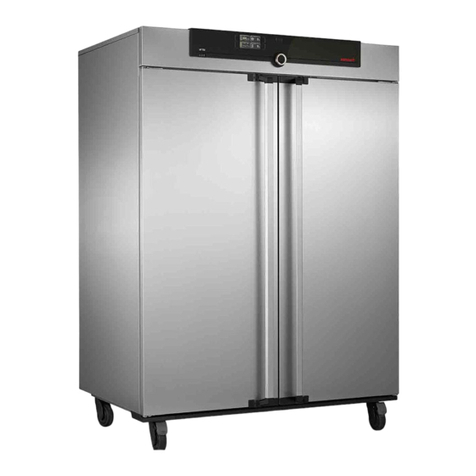
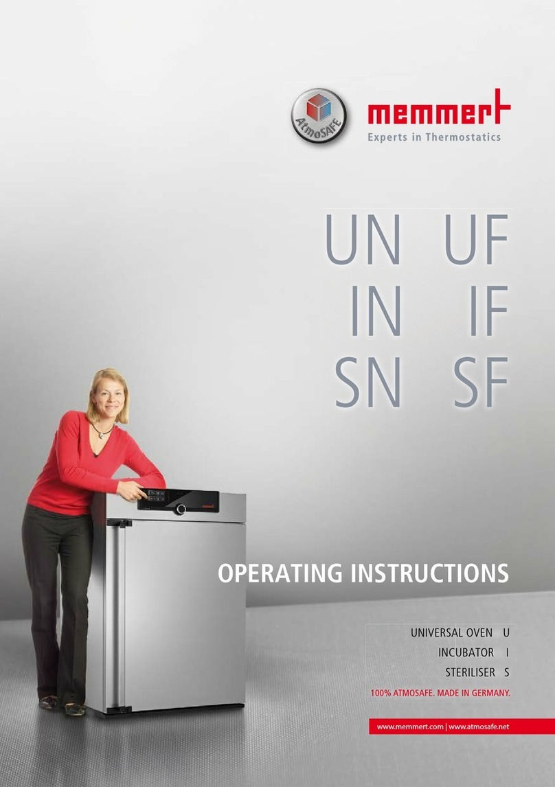
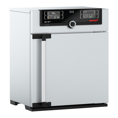
Memmert BASIC Operating instructions

SERVICE - UIS
BASIC EXCELLENT PERFECT
set
off
on
Th Fr
Mo Tu We Sa Su t3
t2
t1
STERI DEFRO
PRINT SETUP
loop
t4 3
4
2
1
°C rh
mb
%CO
mb
2
IN 1 IN 2 OUT IN 1 IN 2 OUT
MIN
AUTO
MAX
°C
h
on
off
U
I
S
page 1
Universal ovens
Incubators
Sterilisers
Service Instructions

SERVICE - UIS page 2

SERVICE - UISpage 3
1. Contents
1. Contents...................................................................................................................................................................... 3
2. Safety notes................................................................................................................................................................. 4
3. Repair instructions ....................................................................................................................................................... 5
4. Fault finding and error messages..................................................................................................................................5
4.1 Additional error messages on 3-phase ovens (Model Uxx 700-800) ....................................................................6
5. Tools required .............................................................................................................................................................. 6
6. Removing the housing cover ........................................................................................................................................ 7
7. Overall view control chamber ....................................................................................................................................... 8
8. Replacing the power unit ...........................................................................................................................................10
9. Changing fuses .......................................................................................................................................................... 10
10. Replacing main switch module incl. turn control ........................................................................................................11
11. Replacing controller (BASIC) .......................................................................................................................................12
12. Replacing controller (EXCELLENT) ...............................................................................................................................13
13. Replacing controller (PERFECT) ................................................................................................................................... 14
14. Replacing temperature limiter TB................................................................................................................................ 15
15. Replacing control chamber fan................................................................................................................................... 16
16. Replacing Pt100 temperature probe ...........................................................................................................................16
17. Changing the circulating fan motor............................................................................................................................17
18. Adjusting and dismantling the inner door on incubators (Ixx) .....................................................................................18
19. Door – maintenance and adjustment .........................................................................................................................19
19.1. Dismantling the door.......................................................................................................................................19
19.2. Adjusting the door...........................................................................................................................................19
19.3.Door closure – maintenance and dismantling .....................................................................................................20
20. Replacing the door seal..............................................................................................................................................22
21. Changing the working chamber seal ..........................................................................................................................22
22. Replacing the heating ................................................................................................................................................23
22. Wiring diagram..........................................................................................................................................................26
24. Index .........................................................................................................................................................................34
25. Address and customer service ....................................................................................................................................35

SERVICE - UIS page 4
2. Safety notes
Always before dismantling the equipment – pull out the mains supply
plug!
Work involving opening the housing must only be carried out by a
qualified electrical technician!
Please observe the safety notes and instructions in the Operating
Instructions supplied with the equipment!
Dismantling the equipment may give access to unfinished metal edges,
therefore always wear gloves during all work!
Observation of the notes in these Service Instructions is essential for
correct operation of the oven. Disregarding these instructions results in
exclusion of warranty, guarantee and damage claims!
On first start-up after any maintenance or repair the equipment should
not be left unsupervised until steady conditions have been reached!

SERVICE - UISpage 5
3. Repair instructions
These instructions describe service and maintenance operations as well as steps for dismantling of BASIC,
EXCELLENT and PERFECT ovens.
Unless otherwise described, assembly takes place in the reverse order.
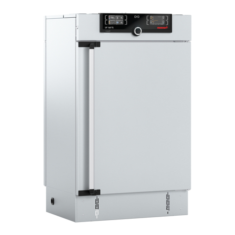
Alterations in technical matters are reserved. Measurements are not binding.
4. Fault finding and error messages
Fault details
Fault details
Fault cause
Fault cause
Fault rectification
Fault rectification
Section
Section
General faults
General faults
Controller display
remains dark
Fuse 100 mA (80 mA) has blown Check fuse and replace if nec. Section 9
Main fuse 15 A has blown Check fuse and replace if nec. Section 9
Power unit faulty Replace power unit Section 8
Temperature can not be
set and oven can not
be operated by turn
control.
Turn control faulty Replace main switch module incl. turn control Section 10
Oven “blocked” by UserID card Unblock using UserID card siehe
Betriebs-
anleitung
Error messages in monitor indication
Warning – symbol
alight continuously
Mechanical-action temperature limiter has switched off
the heating
- Switch off oven and allow to cool down.
- Check Pt100 temperature probe.
- Check temperature limiter
- The oven is again ready for operation only after fault
has been rectified and the oven has cooled down.
Section 14
Warning – symbol
flashing
Monitor controller has switched off the heating because
temperature difference
between working controller and monitor controller is
too small.
Increase temperature difference between monitor
temperature and working temperature.
If nec. replace Pt100 temperature probe on monitor
controller
Section 16
Error message „E-3“ Pt100 temperature probe of monitor controller is
faulty.
Replace Pt100 temperature probe of monitor controller
on connector J3
Section 16
Error message
„E-3” alternating with
temperature display
Pt100 temperature probe of monitor controller is
faulty. Monitor controller operates in emergency mode
with temperature value of working controller Pt100
temperature probe
Replace Pt100 temperature probe of monitor controller
on connector J3.
Section 16
Error message in timer display
Error message „E-0“ Serious configuration error (e.g. incorrect oven type or
incorrect temperature range)
Replace controller Section 11-
13
Error message „CONF”
(display only appr. 10
sec after switching on)
Checksum error (error on storing the setpoints, e.g. fan
speed)
The fault can be rectified by the controller itself after
repeating the storage function of a setpoint parameter.
If the fault is repeated or can not be rectified, the
controller has to be replaced
Section 11-
13
Error message „E-L1” in
timer display
Interruption in communication to power unit Check connecting cable.
If nec. replace power unit
Section 8
Error messages in temperature display
Error message „E-3” Pt100 temperature probe of working controller faulty Replace Pt100 temperature probe of working controller
on connector J4
Section 16
Error message „E-3”
alternating with
temperature display
Pt100 temperature probe of working controller is
faulty. Working controller operates in emergency mode
with the temperature value of monitor controller Pt100
temperature probe.
Replace Pt100 temperature probe of working controller
on connector J4.
Section 16
Error message „E-1.1” Power unit triac 1 faulty Replace power unit Section 8
Error message „E-1.2” Power unit triac 2 faulty Replace power unit Section 8
Error message „E-2.1” Power unit faulty Replace power unit Section 8
Error message „E-2.2” Power unit faulty Replace power unit Section 8
SERVICE - UIS page 6
4.1 Additional error messages on 3-phase ovens (Model Uxx 700-800)
Error messages in timer display
Error message „E-L1”
in timer display
Communication to power unit phase L1 address#0
interrupted
Check fuse.
Check connecting cable.
If nec. replace power unit
Section 8
Error message „E-L2”
in timer display
Communication to power unit phase L2 address#1
interrupted
Check fuse.
Check connecting cable.
If nec. replace power unit
Section 8
Error message „E-L3”
in timer display
Communication to power unit phase L3 address#2
interrupted
Check fuse.
Check connecting cable.
If nec. replace power unit
Section 8
Error message „E-LA” Communication to all power units interrupted Check fuse
Check connecting cable
Check coding switch setting
If nec. replace power unit
If nec. replace controller
Section 8
Section 11-13
Error messages in temperature display
Error message „E-1.1” Power unit phase L1 address #0 triac 1 faulty Replace power unit phase L1 address #0 Section 8
Error message “E-1.2” Power unit phase L1 address #0 triac 2 faulty Replace power unit phase L1 address #0 Section 8
Error message „E-1.3” Power unit phase L2 address #1 triac 1 faulty Replace power unit phase L2 address #1 Section 8
Error message „E-1.4” Power unit phase L2 address #1 triac 2 faulty Replace power unit phase L2 address #1 Section 8
Error message “E-1.5” Power unit phase L3 address #2 triac 1 faulty Replace power unit phase L3 address #2 Section 8
Error message “E-1.6” Power unit phase L3 address #2 triac 2 faulty Replace power unit phase L3 address #2 Section 8
Error message „E-2.1” Power unit faulty Replace power unit Section 8
Error message „E-2.2” Power unit faulty Replace power unit Section 8
Error message „E-2.3” Power unit faulty Replace power unit Section 8
Error message „E-2.4” Power unit faulty Replace power unit Section 8
Error message „E-2.5” Power unit faulty Replace power unit Section 8
Error message „E-2.6” Power unit faulty Replace power unit Section 8
5. Tools required
Torx screwdriver size 8 and 10
Phillips screwdriver
Side-cutter pliers
Flat pliers for pulling off the connecting cables
Socket keys/spanners SW5.5 SW10 SW13
Hexagon socket driver 2 mm for door hinge
Multimeter with voltage and resistance ranges
Cable binder
Adhesive tape for identifying cables and assemblies

SERVICE - UISpage 7
6. Removing the housing cover
Pull off the mains plug !
Unscrew 4 screws on the back of the oven
Slightly raise the cover at the back and pull out towards the back
During re-assembly, check that there are spring washers underneath the screws in order to ensure
secure protective earth connection to the cover
•
•
•
•
back of the oven

10
7
1
6
12
2
8
6
5
4
13
3
7. Overall view control chamber
1 = main switch
2 = power unit
3 = controller (see also Section 11-13)
4 = turn control
5 = air flap (xxB/xxE)
6 = heater terminals
7 = control chamber fan (not on xxB and Ixx)
8 = main connection terminal
9 = air flap servo (P only)
10 = air flap spindle
11 = feed-through heating (600 – 800)
12 = feed-through Pt100 temperature probe
13 = feed-through temperature limiter
14 = chip card reader (xxP only)
Example SNE 500

8
11
7
10
12
12
1
914
1
6
8
10
2
3
3
45
13
4
13
2 (phase L3 address#2)
2 (phase L1 address#0)
2 (phase L2 address#1)
Example INB 200
Example UFP 800

SERVICE - UIS page 10
8. Replacing the power unit
Pull out the mains supply plug!
Remove the housing cover
Pull off all cables from power unit
(if nec. apply markers to unmarked cables)
Release 4 screws from power unit (ensure that spacers are not lost)
•
•
•
•
•
9. Changing fuses
Pull out the mains supply plug !
Remove the housing cover
The two fuses are located on the power unit (see above)
Check the fuse resistance with a continuity tester.
If the fuse is OK the resistance is only a few Ohm.
To change the fuse, place an insulated screwdriver from the side underneath the fuse and twist it to
lift out the fuse from its holder. Push the new fuse from above into the holder.
Main oven fuse: 15 A fast 32 x 6.3 mm (American)
Fuse controller/display: EXCELLENT / PERFECT 100 mA slow 20 x 5 mm
BASIC 80 mA slow 20 x 5 mm
•
•
•
•
•
•
Screw
Spacer
Main oven fuse
Fuse
controller/display
S25/26
Temperature limiter
Circulating fan
S30
Fan
Heating
S 28 Controller/display
Main terminal
supply
black=S20
N=S1
L=S2
blue=S13
brown=S19

SERVICE - UISpage 11
10. Replacing main switch module incl. turn control
Pull out the mains supply plug!
Remove the housing cover
Pull off turn control knob
Pull off connector (4-pin) from controller position J2
Unscrew Phillips headed screws (2x) from main switch module
Pull out main switch module towards the back
(slightly raise the main switch module – note magnet on module underside)
•
•
•
•
•
•
Turn control knob
Magnet
Screws
Connector for
controller position J2
Raise approx. 2 mm during removal

SERVICE - UIS
J
J
13
13
J
J
4
4
J
J
2
2
page 12
11. Replacing controller (BASIC)
Pull out the mains supply plug!
Remove the housing cover
Pull off the turn control knob towards the front
Cut the cable binder with the side cutters and remove it
Release the screw from the air flap spindle and remove the spindle
Disconnect the cable (8-way) for power supply from controller location J13
Remove connector (4-pin) for Pt100 working controller from controller location J4
Remove connector (4-pin) for main switch from controller location J2
Release three fixing screws (see ill.)
Remove the controller towards the back
•
•
•
•
•
•
•
•
•
•
Cable binder
Fixing screws
controller/display
Screw air flap spindle Cable binder
Example INB 200

SERVICE - UIS
J
J
13
13
J
J
4
4
J
J
2
2
J
J
3
3
J
J
9
9
page 13
12. Replacing controller (EXCELLENT)
Pull out the mains supply plug!
Remove the housing cover
Pull off the turn control knob towards the front
On 250°C/300°C ovens (UNE, UFE, SNE, SFE) unscrew the control chamber fan
Cut the cable binder with the side cutters and remove it
Release the screw from the air flap spindle and remove the spindle
Disconnect the cable (8-way) for power supply from controller location J13
Remove connector (4-pin) for Pt100 monitor controller from controller location J3
Remove connector (4-pin) for Pt100 working controller from controller location J4
Remove connector (10-pin) for RS232 interface from controller location J9
Remove connector (4-pin) for main switch from controller location J2
Release three fixing screws (see ill.)
Remove the controller towards the back
•
•
•
•
•
•
•
•
•
•
•
•
•
Cable binder
Screws for control
chamber fan
Screw air flap spindle Cable binder
Fixing screws
controller/display
Example
SNE 500

SERVICE - UIS
J
J
1
1
J
J
13
13
J
J
4
4
J
J
2
2
J
J
3
3
J
J
9
9
J
J
8
8
J
J
11
11
page 14
13. Replacing controller (PERFECT)
Pull out the mains supply plug!
Remove the housing cover
Pull off the turn control knob towards the front
On 250°C/300°C ovens (UNP, UFP, SNP, SFP) unscrew the control chamber fan
Cut the cable binder with the side cutters and remove it
Disconnect the cable (8-way) for power supply from controller location J13
Remove connector (4-pin) for Pt100 monitor controller from controller location J3
Remove connector (4-pin) for Pt100 working controller from controller location J4
Remove connector (10-pin) for RS232 interface from controller location J9
Remove connector (30/22-pin) for printer interface from controller location J8
Remove connector (4-pin) chip card reader from controller position J11 and disengage it
Remove connector (4-pin) air flap servoce from controller position J1
Remove connector (4-pin) for main switch from controller location J2
Release three fixing screws (see ill.)
Remove the controller towards the back
•
•
•
•
•
•
•
•
•
•
•
•
•
•
•
Cable binder
Screws for control chamber fan
Cable binderFixing screws
Example UFP 800

SERVICE - UIS
S
S
25
25
S26
S26
S25
S25
S26
S26
page 15
14. Replacing temperature limiter TB
Pull out the mains supply plug!
Remove the housing cover
Disconnect the earth connection on the back panel and pull out the back panel upwards.
Expose insulation
Unscrew mounting for TB
Pull off temperature limiter from power unit S25 and S26 (see Section 8)
•
•
•
•
•
•
Temperature limiter
(80°C)
Temperature limiter
(230°C / 260°C / 320°C)

SERVICE - UIS page 16
15. Replacing control chamber fan
Pull out the mains supply plug!
Remove the housing cover
Pull off the chamber cabinet fan from the power unit location S30 (see Section 8)
Remove screws on control chamber fan
•
•
•
•
16. Replacing Pt100 temperature probe
Pull out the mains supply plug!
Remove the housing cover
The temperature probe can be carefully slid out
of the clamp towards the back and threaded
upwards through the working chamber ceiling
Probe for working controller:
pull off Pt100 probe from 4-pin controller location
J4 (see Section 11-13)
Probe for monitor controller:
Pull of Pt 100 probe from 4-pin controller location
J3 (see Section 11-13)
Cut the cable binder with the side cutters and
replace the Pt100 probe
•
•
•
•
•
•
•
•
Warning!!
Ensure that the Pt100 probe is fitted correctly in its clip!
Pt100 probe must be secured level at the back in the clip.

SERVICE - UIS
2
4
5
1
3
7
8
6
10
9
page 17
17. Changing the circulating fan motor
Pull out the mains supply plug!
Remove the housing cover
To replace the circulating fan motor it is first
necessary to take off the fan duct cover (2) in
the working chamber after releasing the two
screws (1).
The fan disc (5) can be pulled off after
removing the cap nut (4)
(Note! left-hand thread)
•
•
•
•
Disconnect the earth connections on the back panel and pull out the back panel upwards
Disconnect the earth connection and cable connection from the motor at the power unit
(see Section 8)
After releasing the hexagon nuts (6) the motor baseplate has to be removed together with the
•
•
•
fan motor.
On the back of the motor baseplate the screws (7)
can now be unscrewed and the motor pulled out.
•
•
During assembly it is necessary to ensure that the spacers (8) are again
positioned between motor baseplate and working chamber back
wall. Ensure that the air guide (3) is directed upwards and that the
lockwasher (9) and brass washer (10) are fitted as shown.

SERVICE - UIS
1
3
2
page 18
18. Adjusting and dismantling the inner door on incubators (Ixx)
Release the screws (1), do not unscrew the screws completely, otherwise the fixing block (inside)
drops down.
Adjust the inner door (3) and tighten the screws (1) again.
Check screw (2) and tighten if necessary.
If the fixing block has dropped down, access to it is obtained by pulling out the side panel so that it can
be fitted again.
To dismantle the inner door, release the screw (2) (hold with a spanner), tilt the glass door to the front and
lift it out of the bottom hinge.
•
•
•

SERVICE - UIS
12
4
7
6
3
4
5
2
page 19
19. Door – maintenance and adjustment
19.1.Dismantling the door
Release the screws (5).
Pull out the door (3) horizontally in the
direction of the arrow.
When re-fitting the door, note the following:
Apply thin Silicone grease to the moving
parts of the door hinges (see also Operating
Instructions “Maintenance”)
Place a special washer at the bottom door
hinge between excentric (4) and door.
When re-fitting the door, ensure that the
adjusting notch of the excentric (4) is towards
the front.
Replace the screws (5) and tighten them.
19.2.Adjusting the door
The top part (6) of the door hinge can
be moved slightly in the direction of the
arrow after releasing two screws (7) on the top
or bottom of the door.
The door can be adjusted after releasing the
socket screw (2) by rotating the excentric (4)
with a screwdriver.
NOTE! Screw (2) is locked with adhesive.
It can be released by a sharp tug using a
hexagon socket key.
Apply fresh adhesive to screw (2) and tighten it.
Details of excentric:
•
•
•
•
•
•
•
•
•
•
•
Excentric set to the front
factory-setting
Excentric set to the right,
the door is moved to the right

SERVICE - UIS
1
3
9
8
6
7
4
12
11
page 20
19.3.Door closure – maintenance and dismantling
Release the screws and remove the closure cover. (On Models 600-800 there is no closure cover,
only unscrew and lift the radiation shield)
On back-ventilated doors the insulation has to be removed completely and the air guides removed.
The door closure can now be dismantled in the order 1 to 5
After removing the clips (12) it is possible to dismantle the tension spring (11), the spindles (10),
the closure arms (9) and the closure bolt (8).
•
•
•
•
Closure cover
Screws
Door
Door seal
Radiation shield
This manual suits for next models
2
Table of contents
Other Memmert Oven manuals

Memmert
Memmert UNE 200 User manual

Memmert
Memmert UF450plus User manual

Memmert
Memmert UN Series User manual

Memmert
Memmert UE 800 User manual

Memmert
Memmert VO Series User manual

Memmert
Memmert VO200 User manual

Memmert
Memmert UN User manual

Memmert
Memmert UN PLUS User manual

Memmert
Memmert SF Series User manual

Memmert
Memmert UE 200 User manual
Popular Oven manuals by other brands

Electrolux
Electrolux EOU5410BAK user manual

Siemens
Siemens HM656GB 1 Series User manual and installation instructions

aumate
aumate TO5712A-UL instruction manual

GE
GE JKP75SPSS Dimensions and installation information

Respekta
Respekta AB600-19 manual

Siemens
Siemens HB722G1 1S Series User manual and installation instructions