Mercado Medic REAL 6100 PLUS User manual

REAL®6100 PLUS
with LiNX control system
ENG
Doc. no: 20-06923-UK
Revision: 01
Created: 2020-03-09
Updated: 2020-12-04
User manual
Instructions for use and care

2
REAL® 6100 PLUS with LiNX control system
20-06923-UK-01
The REAL 6100 PLUS is a Class I medical device. It is CE marked in
accordance with the Swedish Medical Products Agency’s code of statutes
for medical devices, LVFS 2003:11, and has been tested and approved in
accordance with EN 12184, ClassA. All textiles used for the chair have
been tested and approved in accordance with EN1021-1 and EN 1021-2.
Mercado Medic AB is certified to both ISO 9001 and 14001 and complies with
applicable labour and environmental legislation.
If you have any questions about your product or if something unexpected has
happened, please contact your dealer first, otherwise you are welcome to
contact us at Mercado Medic AB.
PDF versions of our instructions for use and care with magnification options
can be found on our website: www.mercado.se. Information is also provided
on the website about accessories that can be installed on Mercado Medic’s
chairs, as well as any field safety notices, prescribing support or recalls of
products and accessories.
We reserve the right to make changes to this manual and its contents.

3
REAL® 6100 PLUS with LiNX control system
20-06923-UK-01
Table of Contents
1. Important information ............... 4
2. Expected service life................. 5
3. Symbols on the product .............. 5
4. Before use ......................... 6
4.1. Inspecting the control unit .............. 6
5. Storage, cleaning & maintenance ...... 6
6. Technical information and dimensions . 7
6.1. Technical information................... 7
6.2. Standard dimensions ................... 7
7. Transfers........................... 8
7.1. Transferring to and from the chair ........8
8. Your REAL®6100 PLUS ............... 9
9. Setup & use .......................10
9.1. Armrests.............................10
9.2. Installing the backrest .................10
9.3. Backrest mechanisms:.................10
9.4. Transport services ....................12
9.5. Seat tilt ..............................12
9.6. Reversed tilt or Backward seat tilt only
(option)..............................13
9.7. Leg support ..........................13
9.8. Adjusting the position of the control unit . 14
9.9. Disengaging the brake .................14
9.10. Programming unit .....................14
9.11. Control unit LiNX REM211 ..............15
9.12. LiNX keypad ..........................16
9.13. Control unit LiNX REM400 ..............16
9.14. Charging .............................18
9.15. Sealed lead/acid batteries,
recommendations.....................19
10. Reconditioning & Service...........20
10.1. Indication of malfunction ..............20
10.2. Error codes & actions, control unit.......20
10.3. Troubleshooting & actions, REAL 6100
PLUS ................................21
10.4. Programming diagram; Standard ........21
10.5. Reconditioning instructions: Checkpoints. 22
10.6. Instructions for destruction ............24

4
REAL® 6100 PLUS with LiNX control system
20-06923-UK-01
1. Important information
The REAL6100PLUS has exchangeable components, accessories and functions with setting options for individual
adaptation. The chair must only be used by the person for whom, and for the purpose for which, it is intended.
The chair is intended for indoor use only and must not be used outdoors. The chair must not be exposed to
extreme cold or heat, prolonged sunlight or other radiation. The chair must not be exposed to water, other fluids
or chemicals.
Warning! Metal surfaces may become very hot if they are exposed to direct sunlight. The chair must not be
equipped with any accessories or components other than those approved by Mercado Medic AB. Repairs and
other technical measures may only be carried out by personnel authorised by Mercado Medic AB.
• The REAL6100PLUS is a ClassA product and is
intended for indoor use only.
• Max. user weight: 135kg. When adapting the
product for heavier users, please contact Mercado
Medic AB.
• Driving programs must be adapted for the user
so that the chair can be operated in a safe
manner with regard to the user and the user’s
surroundings. Adaptation of driving programs
may only be carried out by trained prescribers
and technicians. Programming is done using
appropriate software. Please refer to the section
on ‘Programming the control unit’.
• The REAL6100PLUS must not be equipped with
any accessories or components other than those
approved by Mercado Medic AB.
• Warranty period two (2) years unless otherwise
agreed. For warranty cases, please contact
Mercado Medic AB.
• Max. service life ten (10) years.
• Repairs and other technical measures may only be
carried out by personnel authorised by Mercado
Medic AB.
• Chairs with adjustable seat tilt must be in a fixed
position when transferring to or from the chair.
• The REAL 6100 PLUS must not be driven when the
seat height is in the raised position. If the seat is
raised, the obstacle-climbing capability may be
reduced as the chair runs more slowly and less
power reach the drive wheels. To climb obstacles
safely, drive the chair at the lowest possible seat
height.
• The REAL6100PLUS comes with backrest, seat
and leg support as standard.
• The chair is approved for all types of transport. In
all cases the automatic fuse must be switched off
during transport.
• If the REAL6100PLUS is equipped with leg
support, the user’s feet must remain on the
footplate when using the electrical functions.
• Be careful when lifting the battery pack as it is
heavy and can cause crush injuries if dropped.
• When servicing, always reinstall the battery
terminal protective cover. The absence of the
protective cover may result in personal injury on
the occasion of a later service.
• Do not allow small children to be in the vicinity
of the product unsupervised. The cover plug on
the front cover poses a choking hazard for small
children. Please see Your REAL6100PLUS for
reference.
5
REAL® 6100 PLUS with LiNX control system
20-06923-UK-01
2. Expected service life
The expected service life of the Product is ten years
when used in accordance with the instructions in this
manual. The Product's date of manufacture can be
found together with the serial number on one of the
silver labels on the Product's chassis, marked with
Lev/Del and stated in the format YYWW (number of
year and week).
As a user of the Product, you should contact your
prescriber, technical aids centre or distributor if the
Product shows reduced or altered performance.
After the expected service life, it is important to
make an overall assessment of the Product before
continuing to use it. After the expected service life,
Mercado Medic AB cannot guarantee the suitability
and safety of the product, as Mercado Medic AB has
no control over how the product has been used and
wear and tear. The overall assessment of the Product
should be carried out by the healthcare organisation if
the product is prescribed, and, as a minimum, should
take into account how the Product has been used,
the condition of the Product and its component parts,
whether the Product has been reconditioned and
been serviced, when this occurred, what actions have
been taken on these occasions and the reason for the
actions.
In markets outside Sweden and Norway where
a distributor has sold the Product directly to the
user (where applicable), and therefore there is no
responsible prescriber, periodic maintenance must
be carried out according to instructions in the section
Reconditioning and Service in addition to the overall
assessment above.
After the expected service life, Mercado Medic AB
cannot guarantee the provision of spare parts. CE
marking is not affected by expected service life.
3. Symbols on the product
All symbols that may be found on the product are
illustrated and explained in the list below.
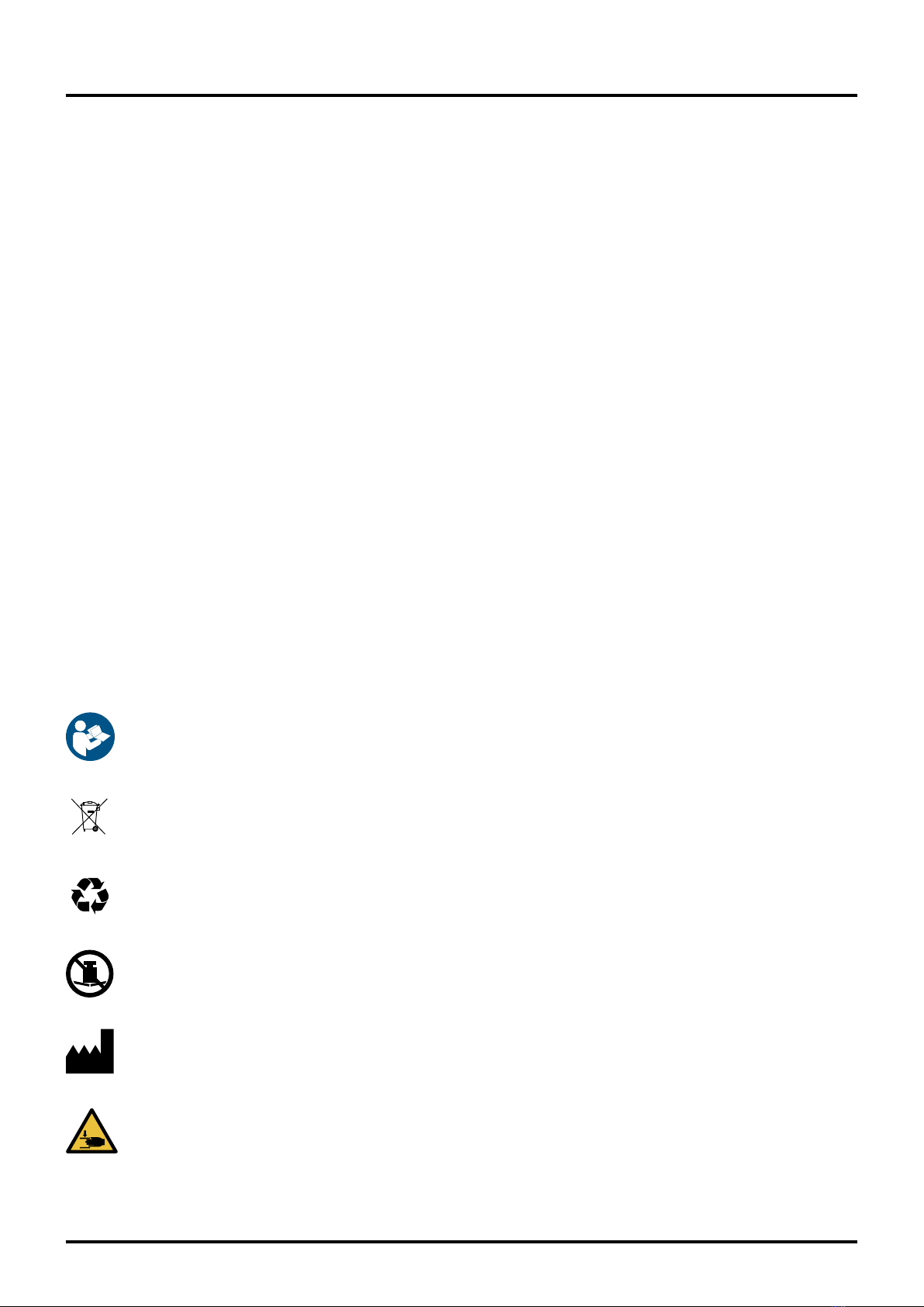
1. Follow the instructions for use
2. Separation of source materials
3. The product is part of a recycling
process
4. Maximum user weight
5. Manufacturer
6. Risk of crush injury. All risks are
indicated
6
REAL® 6100 PLUS with LiNX control system
20-06923-UK-01
4. Before use
• All knobs and locking levers must be tightened on
the chair before use. If play or other deviations are
detected, report this to the responsible technical
aids centre.
• The leg support must not be adjusted so that it is in
contact with the floor or other.
• If the REAL6100PLUS is equipped with, for
example, a belt or similar, this must not hang
loosely on the chair.
• Fold up the armrests. See section8.1.
• Fold down the footplate, 8.2 & 8.3.
• Install the backrest support post. See section 8.7.
• Switch on the automatic fuse. See section7, item6.
• If the chair is equipped with neck support, insert
the neck support mechanism into its bracket on the
backrest as illustrated. Then tighten all knobs and
locking levers (1).
4.1. Inspecting the control unit
• Turn on the main switch.
• The battery level indicator should not be down to
the red mark.
• The display must not indicate error (see
‘Troubleshooting, control unit’ for details of how to
handle error signals).
! Do not operate the chair with the backrest,
footplate and/or armrests removed.
5. Storage, cleaning & maintenance
Service interval: No preventive maintenance is necessary.
Cleaning during use at home: The chair should be wiped
clean of dust and dirt once a week with a lightly moistened
cloth and a mild detergent.
Store the chair in a dry environment at room temperature.
Check the battery charge level before use. If the chair is
to be stored for more than one month, the battery fuse
should be disconnected. See Replacing the battery. The
chair is intended for indoor use and must not be rinsed
with water, other fluids or chemicals. The chair can be
cleaned/wiped clean with surface disinfectants. We
approve the use of detergents with a pH ranging from 7 to
a maximum of 12 (concentrated). The chair must not be
exposed to extreme heat, prolonged and intense sunlight
or other radiation. If the chair has been transported
in extreme cold, it must be allowed to reach room
temperature before use. The chair should be wiped down
and kept clean of dust and dirt.
1. Plush upholstery should be washed using a foam
wash.
2. Remove any dirt, crumbs and similar. Apply a thin
layer of foam and rub the foam evenly with a damp
cloth.
3. Wipe with a clean and lightly dampened cloth.
Vacuum clean when dry.
Artificial leather should be washed using soapy water or
alternatively be wiped down with an alcohol solution, e.g
disinfectants. Do not use any other cleaning agents.
For functional reasons, seats, backrests and other padded
parts are not made from impermeable materials. Padded
parts should be replaced during reconditioning for
hygienic reasons.
The electric lifting mechanism should be checked
regularly for dust, dirt and stability: Raise the seat to its
highest position. Clean with a cloth. Do not use any water
or solvents. Then lubricate the cylinder by applying a thin
layer of Teflon or silicone based grease. Touch-up coating
can be done using Mercado’s black touch-up paint, article
no. 801900.
11

7
REAL® 6100 PLUS with LiNX control system
20-06923-UK-01
6. Technical information and dimensions
6.1. Technical information
Max. user weight................................................................... 135 kg
Drive wheels ........................................................... both centre wheels
Driving distance per charge...................................................approx.15km*
Weight ................................................................. 76kg incl. battery
Motors ............................................. ME803661C Allied Motion Stockholm AB
Charging time ........................................................... approx. 6–8hours
Chargers tested and approved by Mercado Medic AB.....................ECB-401 Easy Buddy 4A
Batteries tested and approved by Mercado Medic AB .............FGS, FGG22805, 2 × 12V 28Ah
6.2. Standard dimensions
Total width.......................................................................570 mm
Length. . . . . . . . . . . . . . . . . . . . . . . . . . . . . . . . . . . . . . . . . . . . . . . . . . . . . . . . . . . . . . . . . . . . . . . . . . . 795 mm
Collapsed height..................................................................550 mm
Static stability ...................................................................+6°/-6°**
Static lateral stability ................................................................... 6°
Dynamic stability ................................................. uphill 10°, downhill 3° ***
Obstacle-climbing ability ...........................................................40 mm
Max. speed ..................................................................... 4.5km/h
Braking distance from max. speed ................................... 1.0m/0.7m active brake
Seat tilt........................................................-15°/+8°, -8°/+15°, 0°/+23°
Seat depth ..................................................................170–540 mm
Seat width ..................................................................290–550 mm
Seat height..................................................... 460–740, 380–580 mm****
Backrest angle ..................................................................-15/+45°
Backrest height..............................................................390–650 mm
Leg support length ........................................................... 370–530 mm
Leg support angle .................................................................0°/+32°
Armrest height .............................................................. 150–300 mm
Backrest-armrest mech. ......................................................100–250 mm
Turning space 180° ...............................................................870 mm
Front/rear wheels .............................................Ø 125 mm (article no. 804362)
Drive wheels .................................................Ø 225 mm (article no. 805203)
* In optimal driving conditions.
** Seat tilt and back tilt settings together with high seat height
can affect both static and dynamic stability.
*** On large downward slopes, the chair must be reversed.
**** Measured from floor to the underside of the seat, with the potential for
continuous downward adjustment to a maximum 3 cm.
8
REAL® 6100 PLUS with LiNX control system
20-06923-UK-01
90°
Transfers from the side
When transferring to the chair from the side, you must aim to ensure that
the seat of the chair is positioned somewhat lower than the position you
are transferring from. When transferring from the chair you can raise the
chair so that you are sitting positioned somewhat higher than the position
you are transferring to. Remember to only fold away or lower the armrest
of the chair on the side you are transferring over.
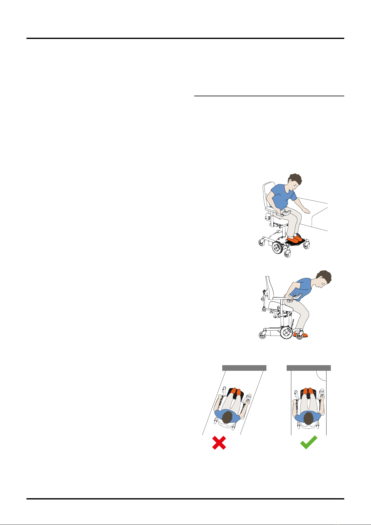
Transfers from the front
When transferring to the chair from the front, you must aim to ensure that
the front edge of the seat is no higher than knee level; this is so you can
sit well back into the seat without having to make further adjustments.
Remember to fold away or lower the footplate so you can get close to the
seat. If you are using a lift to transfer to and from the chair, you must bear
in mind any crushing risk. Make sure that hands, feet and any items of
clothing cannot get in the way and risk injury.
Ramps
Always drive straight up the ramp from the front, not obliquely.
7. Transfers
7.1. Transferring to and from the chair
Please note: Always ask your dealer for advice on the most suitable technique for transferring to and from the
chair, from the front or the side. What best suits you and your needs and thus carries the least risk of injury.
! Transfers to and from the chair must only take place on a flat surface. Position the chair correctly for the
transfer and adjust the seat height to the correct position.
! Ensure that the control unit is switched off and that the brake is not disengaged at the time of the
transfer in order to prevent the chair from moving unexpectedly.
! Before driving on a ramp, check that it can
withstand the combined weight of you and your
electric wheelchair. To increase the stability of
the chair when driving on a ramp, lower the seat
lift and level the seat tilt. When driving down a
ramp we recommend always reversing the chair.
If the slope exceeds 3degrees, the chair must
be reversed when going downhill.

9
REAL® 6100 PLUS with LiNX control system
20-06923-UK-01
8. Your REAL®6100 PLUS
1. Backrest adjustable in
height, angle and depth.
2. Armrests adjustable in
width and height.
3. Control unit (also controls
electrical seat functions).
4. Seat adjustable in height. Seat
tilt is available as an accessory.
5. Warning label with
transport information.
6. Automatic fuse with On/
Off function. Also used to
disconnect the batteries,
e.g. when the chair is to
be transported by air.
7. Label with unique
serial number.
8. Cover plug on front cover
(see risk description under
Important information).
9. Drive wheels, puncture-proof.
10. Footplate adjustable in
height and angle.
11. Castors with individual
wheel suspension.
1 2
3 4
9
11
10
8
5
7
6

10
REAL® 6100 PLUS with LiNX control system
20-06923-UK-01
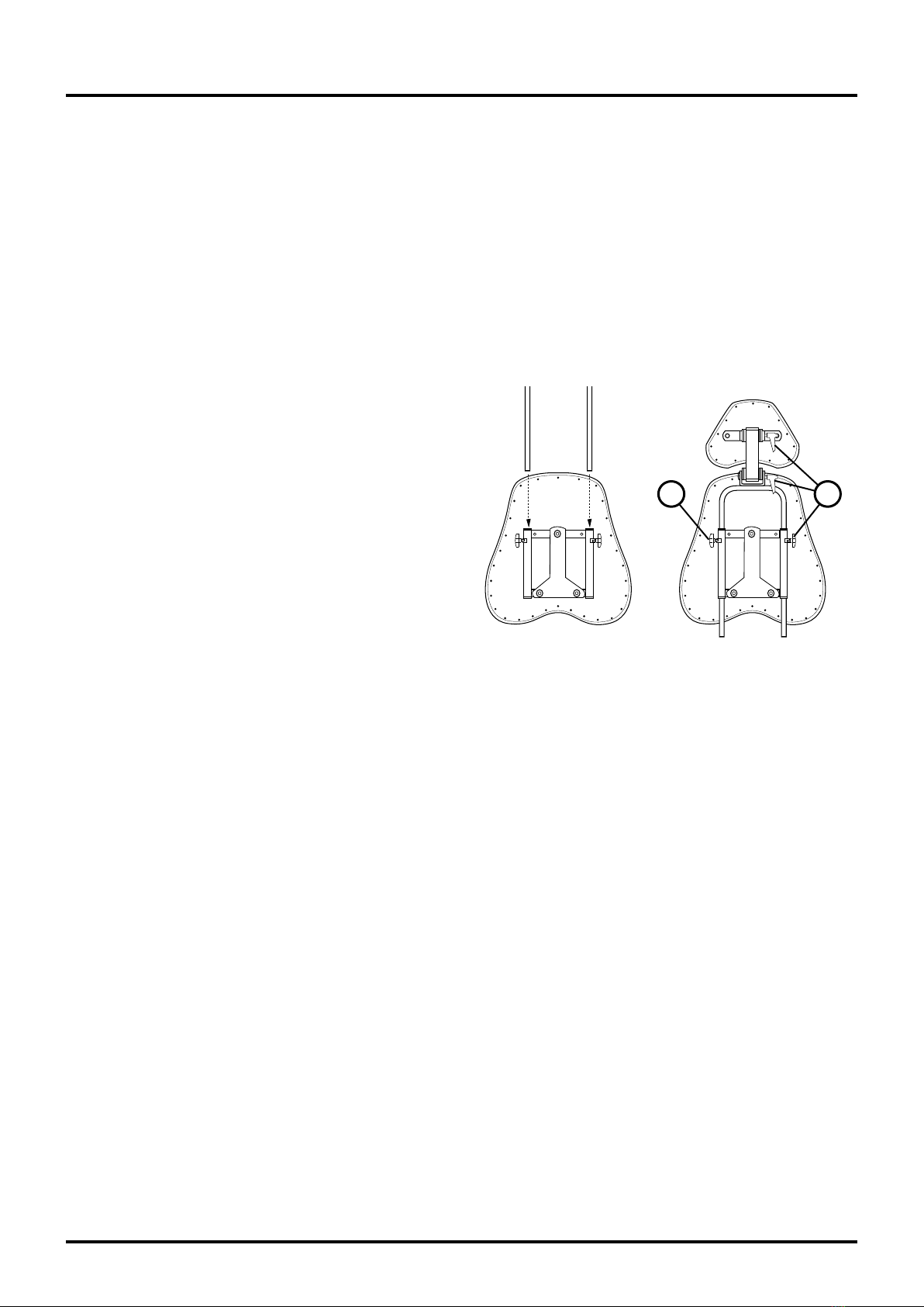
9.2. Installing the backrest
Insert the backrest support post (1) into the backrest
mechanism (2) while pushing in the button clip
(3). Adjust to the appropriate height (see Backrest
mechanisms for instructions on how to adjust the
backrest). Lock the backrest support post using the
knob (4). Dismantling is carried out in the reverse
order.
9.3. Backrest mechanisms:
Adjust the backrest so that the user’s calf is at a distance of about 2–3cm from the front edge of the seat
while in a sitting position. This is to promote blood circulation while maintaining a stable sitting position
when operating the chair.
There are four types of backrest mechanisms: Standard, Medic, Comfort and EL. All are available in a low and high
design (illustrated chairs all have low backrests). All backrest mechanisms have separate settings for height, depth and
angle. The Medic model has extended depth adjustment.
- The Standard backrest mechanism can be adjusted in height, depth and angle and is available with both high
and low backrests.
- In addition to height, depth and angle adjustments, the Medic backrest mechanism (option) has an extended
depth adjustment option.
- The Comfort backrest mechanism (option) looks and works like a Medic backrest mechanism without depth
adjustment, with angle adjustment of the backrest mechanism done using the handle on the gas spring.
- The EL backrest mechanism can be adjusted in height, depth and angle and is available with both high and low
backrests. The mechanism can be set in two different angle adjustment ranges.
Armrest Foldable armrest
9. Setup & use
9.1. Armrests
Controls
1. Height. To adjust the height of an armrest, loosen
the knob (1). Pull/press the armrest to the desired
height. Then tighten the knob.
2. Width. To adjust the width, loosen the locking
mechanism, knob or screw* (2). Pull/press the
armrest to the desired width. Then tighten the
locking mechanism.
3. Folding. To fold the armrest, pull out the pin
and turn through 90° (3). This releases the fold
function. Then fold the armrest backwards.
* Allen key for locking screws included with your chair.
! Remember to turn the pin back again after
folding up the armrest to ensure that the fold
function is locked.
The user can adjust the height and width of the
armrests. If the chair has foldable armrests, these can
also be folded backwards.
1
12
2
3
1
2
3
4
11
REAL® 6100 PLUS with LiNX control system
20-06923-UK-01
Standard
Medic
1
2
3
1
1
2
45
3
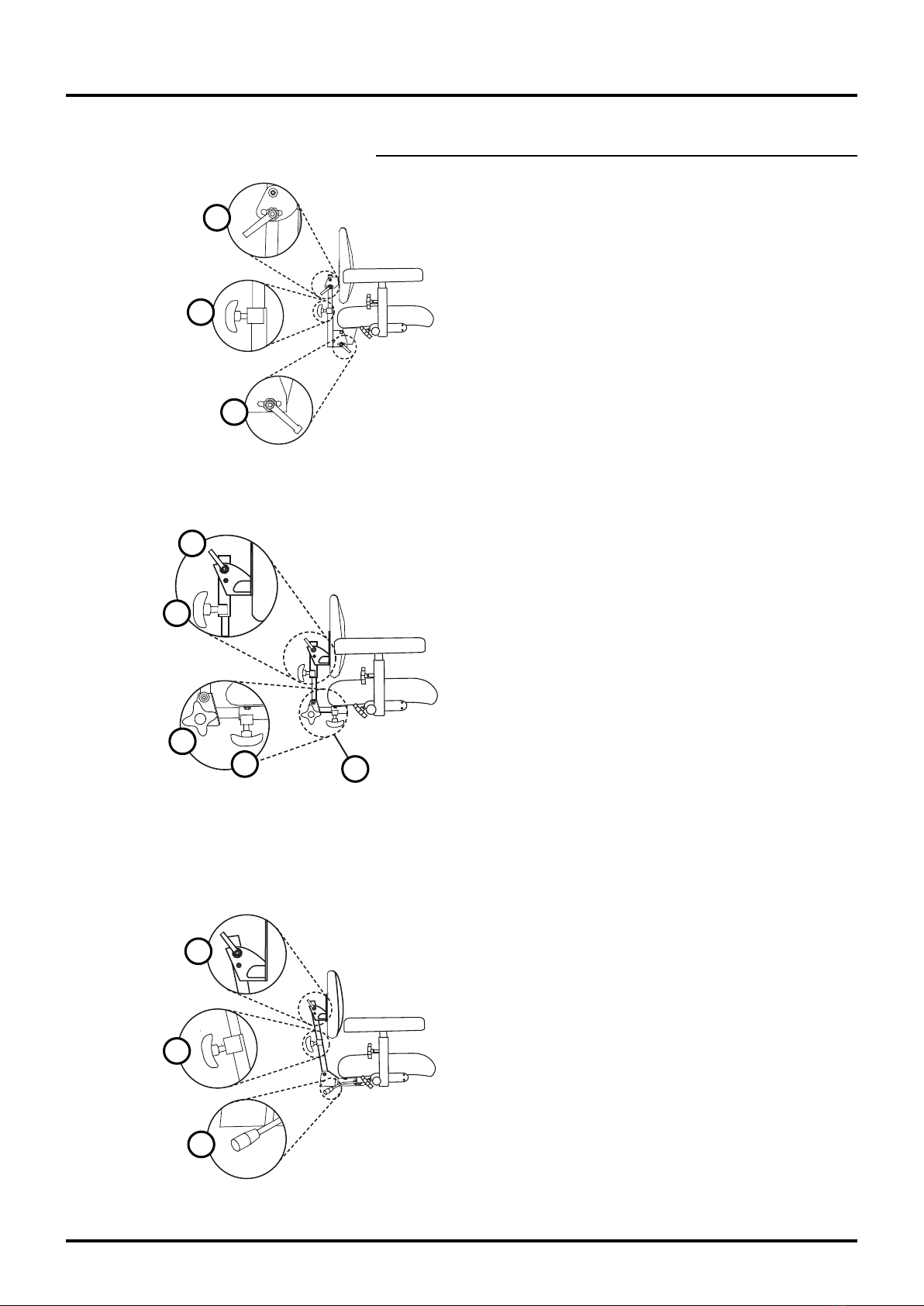
Controls, Standard
1. Height. To adjust the height of the backrest,
loosen the knob (1). Press or pull the backrest to
the desired height.
2. Backrest mechanism angle. To adjust the angle
of the backrest mechanism, loosen the lever (2).
Then place the back mechanism at the desired
angle and tighten the lever.
3. Backrest angle. To adjust the angle of the
backrest, loosen the lever (3). Then place the
backrest at the desired angle and tighten the lever.
Controls, Medic
1. Height. To adjust the height of the backrest,
loosen the knob (1). Press or pull the backrest to
the desired height. Then tighten the knob.
2. Backrest mechanism angle. To adjust the angle
of the backrest mechanism, loosen the knob (2).
Then place the backrest mechanism at the desired
angle and tighten the knob.
3. Backrest angle. To adjust the angle of the
backrest, loosen the lever (3). Then place the
backrest at the desired angle and tighten the lever.
4. Depth. Loosen the knob (4) to adjust the depth of
the backrest mechanism. Then pull or push the
backrest mechanism to the desired depth. Then
tighten the knob.
5. Button clip. When adjusting the depth of the
backrest mechanism, ensure that the button clip
locks and that the backrest mechanism cannot be
pulled out.
Backrest mechanisms, cont.
Controls, Comfort
1. Height. To adjust the height of the backrest,
loosen the knob (1). Press or pull the backrest to
the desired height. Then tighten the knob.
2. Backrest mechanism angle. To adjust the angle
of the backrest mechanism, use the handle
on the gas spring (2). Then place the backrest
mechanism at the desired angle and release the
handle.
3. Backrest angle. To adjust the angle of the
backrest, loosen the lever (3). Then place the
backrest at the desired angle and tighten the lever.
1
2
3
12
REAL® 6100 PLUS with LiNX control system
20-06923-UK-01
Backrest mechanisms, cont.
Controls, EL
1. Height. To adjust the height of the backrest,
loosen the knob (1). Press or pull the backrest to
the desired height.
2. Backrest angle. To adjust the angle of the
backrest, loosen the lever (3). Then place the
backrest at the desired angle and tighten the
lever.
3. Backrest mechanism angle. The angle of the
backrest mechanism is adjusted using the control
unit. Please see the section on Control units.
1
2
EL
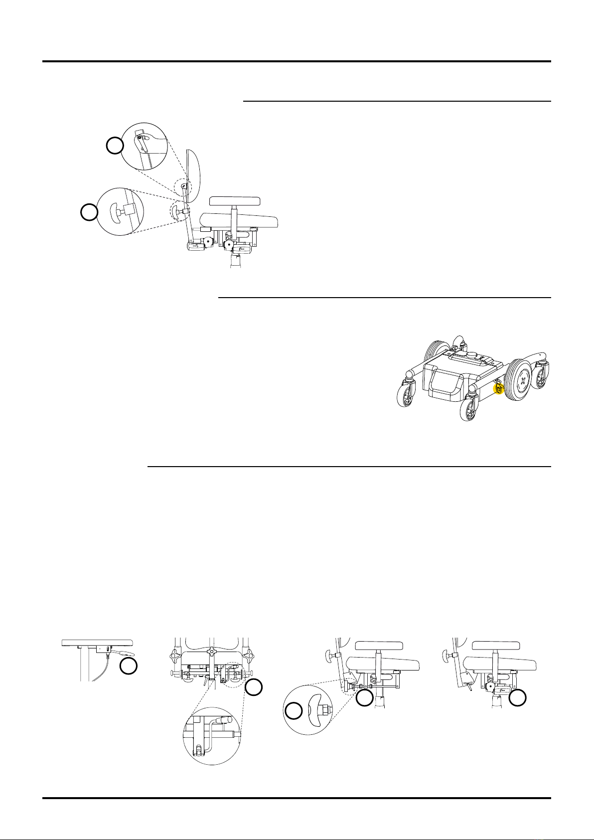
9.4. Transport services
When transporting the REAL6100PLUS by transport services or
equivalent, the user must transfer to the vehicle seat. When using
transport services, the chair must be equipped with transport loops and
must be secured using the straps of the transport vehicle. Also switch off
the automatic fuse by pressing OFF. If the fuse has tripped, it must be
reset by pressing ON. The control unit must be restarted two (2) times in
order to restore the chair’s functions. Transport loops (accessories) can be
ordered using article number TR1010.
! The chair is not approved for sitting in during transport.
9.5. Seat tilt
There are three types of seat tilt: Gas spring, crank-
operated and electric tilt. The gas spring control
is located under one of the armrests (1) or under
the right rear edge of the seat (2) and is adjusted
by carefully moving the lever forward. The crank-
operated seat tilt is operated by a crank (3). The range
of the seat tilt can be limited using the nuts (4). The
electric seat tilt (5) is adjusted using the control unit.
See section Control unit.
Controls
1. Gas spring under armrest.
2. Gas spring under seat.
3. Crank-operated under seat.
4. Nuts on crank-operated tilt.
5. Electric – see section Control unit.
Crank-operated EL
Gas spring
1
3
4 5
2

13
REAL® 6100 PLUS with LiNX control system
20-06923-UK-01
9.6. Reversed tilt or Backward seat tilt only (option)
9.7. Leg support
Controls
1. Armrests placed here follow the seat tilt.
2. Armrests placed here do not follow the seat tilt.
3. There are 3 positions. If using position 3, the chair
must be equipped with base extenders.
3.1. Forward 15˚, backward 8˚ – Standard seat tilt
3.2. Forward 8˚, backward 15˚ – Reversed seat tilt
3.3. Forward 0˚, backward 23˚ – Backward seat tilt only
Centre-mounted
Cross
1
1
3
2
3.1
3.2
3.3
1
2
3
Controls, Centre-mounted
1. Height. To adjust the height of the footplate,
loosen the knob (1). Then pull or push the
footplate to the desired height*.
2. Leg support angle. The angle of the leg support
can be adjusted to four different positions. To
adjust the angle, unscrew the screw (2) using a
5 mm Allen key. Set the desired angle and screw
the screw back in.
3. Footplate angle. To adjust the angle of the
footplate, adjust the screw (3) using a 5mm Allen
key. To lower, turn the screw clockwise. To raise,
turn the screw anticlockwise.
Controls, Cross
1. Height. To adjust the height of the footplate,
loosen the knob (1). Then raise or lower the
footplate to the desired height so that you can
thread the screw through and tighten the wing nut
on the back*.
2. Footplate angle. To adjust the angle of the
footplate, loosen the screws (2) slightly. Use a
5mm Allen key. Angle to the desired position and
then tighten the screws.
* Make sure that you properly insert the knob into one
of the holes in the footplate tube. This is to ensure
that the footplate does not come loose.
! Crush hazard for feet between footplate and
floor. The feet must be kept on the footplate
while operating the chair.
2

14
REAL® 6100 PLUS with LiNX control system
20-06923-UK-01
• Forward speed
• Forward acceleration
• Forward braking distance
• Reverse speed
• Reverse acceleration
• Reverse braking distance
• Turning speed
• Turning acceleration
• Turning deceleration
• Joystick sensitivity
• Use of external joystick
• Reversed joystick function
! Driving programs must be
adapted for the user so that
the chair can be operated in
a safe manner with regard
to the user and the user’s
surroundings.
9.8. Adjusting the position of the control unit
9.9. Disengaging the brake
9.10. Programming unit
Adaptation of driving programs may only be carried out by trained prescribers and technicians.
Selection of programmable functions:
The control unit can be adjusted in depth and width. To adjust the depth,
remove the screw (1) using a 5mm Allen key and a 10mm ring spanner.
Move the control arm to the desired position (three possible) and then
refit the screw. The control unit can be moved to both the inside and the
outside of the armrest.
The control arm is articulated at two points, allowing horizontal lateral
movement of the control unit without using tools. Move the control unit to
the desired position. The control unit can be placed on the right (standard)
or left armrest.
With parallelogram
The magnetic attachment allows for easy adjustment parallel to the
armrest. Adjust the position with the screw (1), then lock the screw. Move
the control unit to the desired position and release.
Disengaging the brake allows the user to move the
chair manually. To disengage, pull the control towards
you (1), downwards in the illustration on the right.
To re-engage the brake, push the control back to
its original position. If the chair is disengaged while
turned on, the control unit will display an alarm and it
will not be possible to operate the chair. Re-engaging
the brake will cause the alarm to disappear and it will
be possible to operate the chair again.
! The chair must never be transported in vehicles
with the brake disengaged.
1
1
1

15
REAL® 6100 PLUS with LiNX control system
20-06923-UK-01
9.11. Control unit LiNX REM211
Operation: Driving
Turn on the power button (1). Check the battery level
indicator (7). The battery level indicator should have
at least 2 bars lit. If only 1 red mark is lit the chair
must be charged (see ‘Charging’). Check to ensure
that the control unit is not indicating error by the
power button flashing red (1).
Driving: check to ensure that the display (9) is
showing a green tyre on the chair symbol and that
the desired driving program (10)
has been selected by pressing the
driving program buttons (2). It is
also possible to adjust the selected
drive program using the control
knob (4).
The chair is operated by moving
the joystick (6) in the direction you
wish to move: straight forward for
forward movement and obliquely
left/right/forward to turn. The
chair can be rotated by moving
the joystick (6) straight to the left/
right.
To brake, release the joystick (6) so
that it comes to rest in the neutral
position (centre), or turn the
joystick in the opposite direction
of the direction of travel for faster
braking. Remember that the
braking distance is affected by the
slope of the surface underneath
the chair.
Downhill = longer braking distance
Uphill = shorter braking distance
To reverse, pull the joystick (6) backwards.
Horn: press button (5).
Emergency stop
If, when driving or using electrical functions,
it is necessary to use the emergency stop, it is
recommended to use the power button (1) to perform
the emergency stop.
This stops the driving/electrical function quickly.
Operation: Seat unit
For raising/lowering the seat unit or the electric seat
tilt/backrest angle or leg support angle. Navigate up/
down the option buttons (3) to view the electrical
functions available on the chair. These can be seen
on the display (9) (one function at a time). Move the
joystick forward/backward to operate the selected
electrical function. It is also possible to use the
joystick when changing the active electrical function
by moving the joystick sideways.
Adjusting the seat height: move
the joystick (6) forward to raise
the seat height and downwards to
lower it.
Adjusting the seat tilt: move the
joystick (6) forward to tilt the seat
forward and downwards to tilt it
backwards.
Adjusting the backrest angle:
move the joystick (6) forward
to tilt the backrest forward and
downwards to tilt it backwards.
Locking* the LiNX REM211
control unit
When the control unit is switched
on, hold down the power button
(1) for 4seconds. The red, amber
and green LEDs will flash three
times on the display (7) before the
control unit is switched off.
Unlocking* the LiNX
REM211 control unit
Press the power button (1) and wait until LEDs 1 =
red, 3 = amber and 5 = green flash on the display.
Press the horn (5) twice within 10seconds. The
control unit is activated.
When the chair’s electrical function has not been
used for approx. five minutes it will shut down
automatically to save battery power. Press any button
to start up the electronics. The time interval for
automatic shutdown is adjustable.
* works only if the function has been activated in the
program.
7
5
9
3
11
4
8
1
2
10
6
Control unit LiNX REM211
16
REAL® 6100 PLUS with LiNX control system
20-06923-UK-01
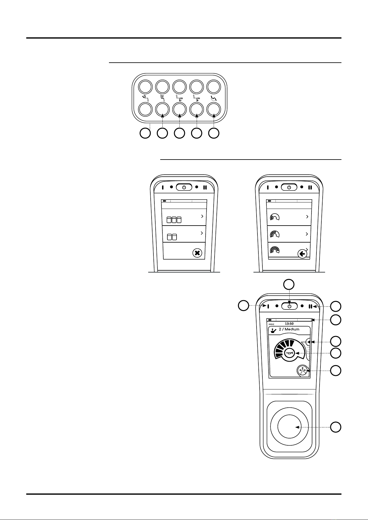
9.12. LiNX keypad
9.13. Control unit LiNX REM400
Operation: Driving
Turn on the main switch (1). Check
the battery level indicator (6) at
the top of the display. The battery
level indicator should display at
least amber. If only the red mark is
lit, the chair must be charged (see
‘Charging’). Check to ensure that
the control unit is not indicating
error by the main switch flashing
red (1).
Start menu: When the electronics
are started, the driving program/
The LiNX keypad provides direct
access to the electrical functions
of the seat unit without exiting the
drive program in the control unit.
The keypad is located between
the control unit and the armrest as
standard.
1 / Slow
DRIVE
2 / Medium
3 / Fast
DRIVE
PROFILES
SEATING
1. Backrest tilt
2. Seat height
3. Electric leg support, Left
4. Electric leg support, Right/
Centre-mounted
5. Seat tilt
1 2 3 4 5
electrical function that was active when the electronics were switched
off is always opened. It is important that the joystick is not actuated
when starting the electronics. No driving program/electrical function will
operate until the joystick is returned to a non-actuated state.
The driving program/electrical function can be selected on the display
using the menu selection symbol (8) or the function keys (4)(5).
Function key 1 (4) alternates between driving programs and electrical
functions; function key 2 (5) navigates between driving programs or
electrical functions in the submenu. If the control unit is not touched for
30seconds, the display is reset to the basic selection menu, with the
driving programs in the top row (green) and the electrical functions in the
bottom row (orange).
To return to the previous driving program/electrical function, press the ‘X’
that is displayed on the menu selection symbol (8) or any of the function
keys (4)(5), or click on the desired new selection in the basic menu or
activate the selected program by moving the joystick up/down, right/left.
Driving: Select the desired driving program using the menu selection
symbol (8) or one of the function keys (4) (5). It is also possible to adjust
the speed of the selected driving program using the speed control (7).
The chair is operated by moving the joystick (3) in the direction you wish
to move: straight ahead for forward movement and obliquely left/right-
ahead to turn. The chair can be rotated by moving the joystick (3) straight
to the left/right.
Control unit LiNX REM400
1
45
6
7
2
8
3
17
REAL® 6100 PLUS with LiNX control system
20-06923-UK-01
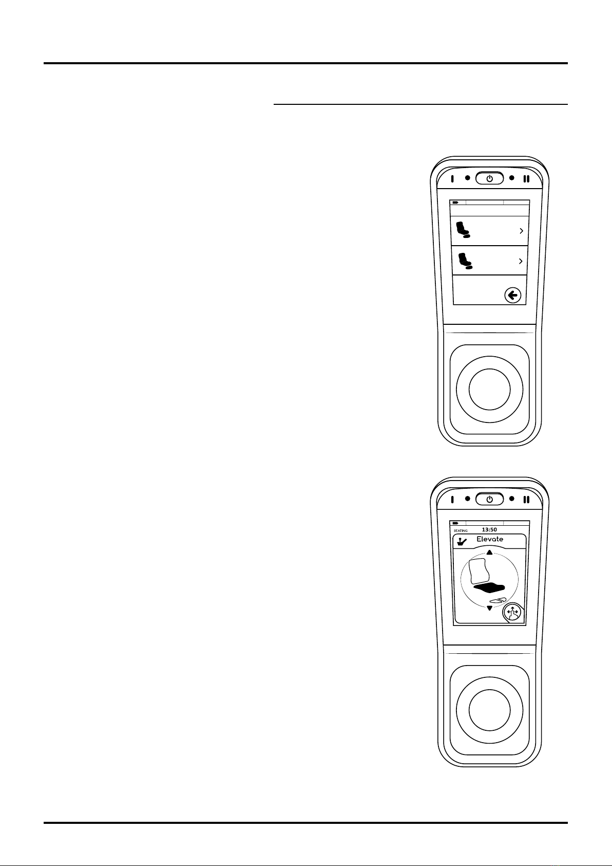
Control Unit LiNX REM400, cont.
To brake, release the joystick (3) so that it comes to rest in the neutral position (centre), or turn the joystick in the
opposite direction of the direction of travel for faster braking. Remember that the braking distance is affected by
Tilt
SEATING
Elevate
the slope of the surface underneath the chair.
Downhill = longer braking distance
Uphill = shorter braking distance
To reverse, pull the joystick (3) backwards.
Emergency stop
If, when driving or using electrical functions, it is necessary to use the
emergency stop, it is recommended to use the main switch (1) to perform
the emergency stop. This stops the driving/electrical function quickly.
Horn: press button (2).
Operation: Seat unit
For raising/lowering the seat unit or the electric seat tilt/backrest angle
or leg support angle. Navigate using the menu selection symbol (8) or
function key 1 (4) to activate the electrical function. Function key 2 (5)
navigates between the different electrical functions. Move the joystick
forward/backward to operate the selected electrical function. It is also
possible to use the joystick when changing the active electrical function by
moving the joystick sideways to the left/right.
Adjusting the seat height: move the joystick (3) forward to raise the seat
height and backward to lower it.
Adjusting the seat tilt: move the joystick (3) forward to tilt the seat forward
and backwards to tilt it backwards.
Adjusting the backrest angle: move the joystick (3) forward to tilt the
backrest forward and backwards to tilt it backwards.
Locking* the LiNX REM400 control unit
When the control unit is on, press and hold down the main switch (1) for
4seconds. The display shows a padlock and all driving programs and
electrical functions are locked.
Unlocking* the LiNX REM400 control unit
Press the main switch (1) and wait until the padlock symbol appears. Press
and hold the padlock symbol within 10 seconds, until the driving program/
electrical function is displayed.
When the control unit has not been used for approx. five minutes it will
shut down automatically to save battery power. Press any button to start
up the electronics or move the joystick forward/backward. The time
interval for automatic shutdown is programmable.
* works only if the function has been activated in the program.
18
REAL® 6100 PLUS with LiNX control system
20-06923-UK-01
The EC-Buddy is equipped with protection against the
following:
• Incorrect polarity
• Short-circuiting of battery cables
• Formation of sparks in grid and battery
• Overheating
The charger should not be exposed to direct sunlight.
The charger must not, fully or partially, be immersed
in water or covered with snow. Cables and connectors
may only be replaced by the manufacturer or an
authorised service centre.
The charger complies with the following standards:
EN 60601-1, EN 60601-1-2, EN 12184, ISO 7176-14.
The combination of chair and charger also complies
with ISO 7176-21.
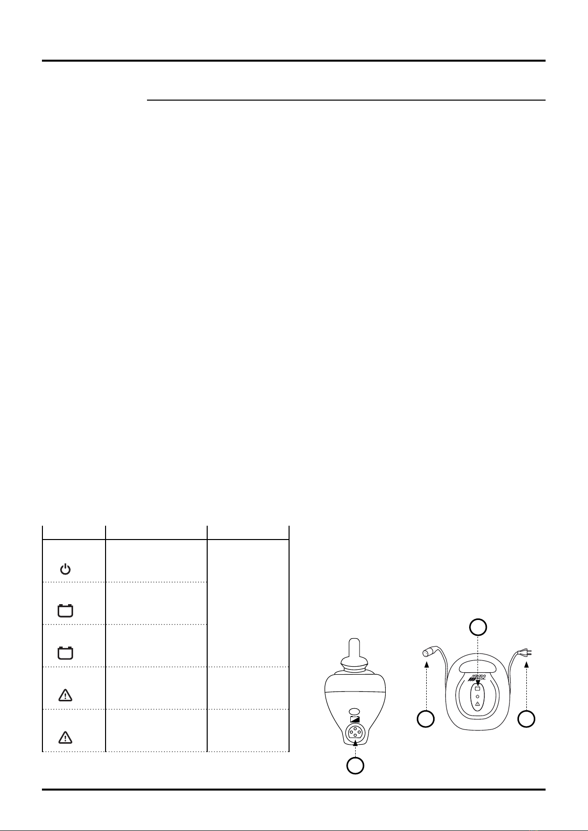
Maintenance-charging of the chair should be carried
out monthly or continuously:
1. Connect the charger power cord (3) to the wall
outlet.
2. Connect the charging connector (1) to the
charging jack (2) (marked with a battery symbol).
The power cord and charging connector can be
connected in any order.
3. The green LED (4) flashes during charging. The
charger becomes warm during charging. This
is perfectly normal. There is protection against
overheating.
4. The green LED (4) will light up when the battery
is ready for use, which takes at least six hours,
regardless of initial battery capacity. As the
charger uses little power and will not overcharge
the battery, it could well be left connected until
the vehicle is to be used.
5. Disconnect the charging connector from the
charging jack (2) when the vehicle is to be used.
6. Disconnect the power cord (3), if desired.
! Warning:
- Batteries emit explosive gases when charging.
Avoid flames and sparks.
- The charger is designed only for lead batteries
with 12 cells (24V).
- The charger is equipped with protection
against overheating but becomes warm during
charging.
- Charging must be carried out in a well-
ventilated area.
- Medical electrical equipment requires special
precautions and must meet the requirements
of ISO 7176-21, where the charger and chair
are tested together according to EMC. The
tests pursuant to this standard check that
our product, the chair incl. charger, cannot
disrupt or be affected by portable or mobile RF
communication equipment.
- Cables and connectors may only be replaced
by the manufacturer or an authorised service
centre.
- Excessive heat build-up in any connector is a
sign of wear or damage. Both the female and
male connectors should be replaced in such
cases.
9.14. Charging
2
2 3
4
Battery charger 6100 PLUS, 4 amp.
Article no. BAC1010.
Indication
Steady light
Flashing
Steady light
Steady light
Flashing
Meaning/Cause
Plugged in
Battery charging
Battery fully charged
Incorrect polarity to
battery
Battery fault
Action
Contact Service
Contact Service
19
REAL® 6100 PLUS with LiNX control system
20-06923-UK-01
Care & supervision
• Before each charge, check that
cables and connectors are not
damaged or worn. If this is
the case, the charger must be
replaced immediately.
• To ensure optimal performance,
economy and service life of
the charger and battery, and
maximum driving distance per
charge, the following guidelines
should be followed:
• Keep the charger, connectors and
batteries free of dirt, dust and
oxide.
• Turn off the
vehicle when
it is not in use.
• Charge the
battery daily,
or as soon as
it is depleted.
• Allow the
charger to perform maintenance-
charging of the battery when the
vehicle is to be stored for a long
time*.
• Clean the charger as required
using a slightly damp cloth.
* As the charger uses little power
and will not overcharge the battery, it
could well be left connected until the
vehicle is to be used.
Charging, cont.
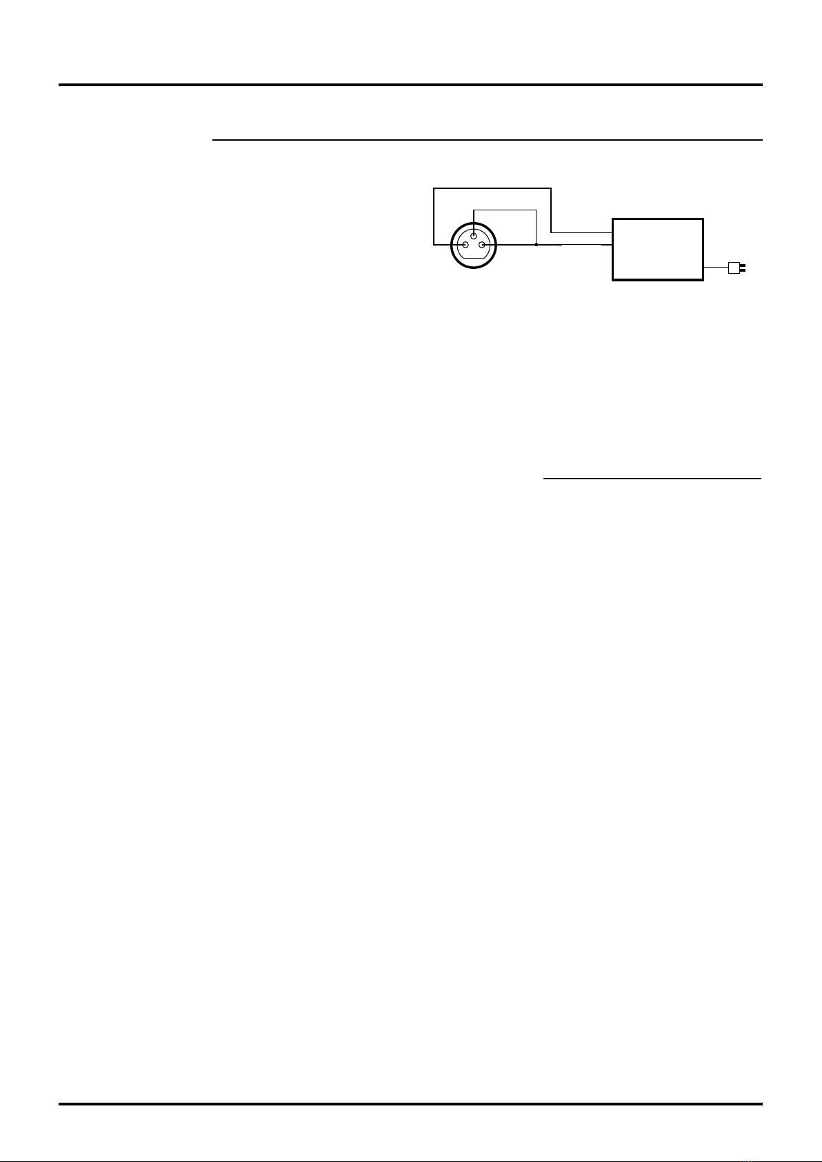
Batteriladdare
skall uppfylla
SS-EN 12184
ISO 7176-21
Laddplugg 3 pin XLR typ
(framifrån)
Batteri --
Förregla
Batteri +
Interlock
Battery -
Battery + Battery charger
must comply
with SS-EN
12184 & ISO
7176-21
Charging plug, 3 pin, XLR
type (front view)
Connection diagram for charging jack
Charging/discharging
• Charge for 12 hours before first use.
• Then charge after each discharge, even if the
battery has not been fully discharged.
• Never place a fully discharged battery away for
storage.
• A fully discharged battery must be charged for at
least 16 hours.
• If the battery has been charged for less than
16hours on more than three occasions, the
battery must be charged once for 24hours in
order to compensate for poor charging.
• The ambient temperature when charging must be
between 10°C and 30°C.
High ambient temperatures
The battery should not be charged if the ambient
temperature exceeds 30°C. The charger is set to a
charging voltage valid at 20°C.
Low ambient temperatures
Charging at temperatures below 10°C is not
recommended. The available capacity decreases at
low temperatures.
Deep discharge
Try to avoid deep discharges. If the battery is
completely discharged, it must be charged as soon as
possible and for at least 24hours.
Long-term storage
Disconnect the batteries if the chair is not to be used
for a long time. This is done using the Automatic fuse.
Press Off to disconnect the batteries. If the chair is to
be left unused for more than 4months, a maintenance
charge must be performed to uphold battery capacity.
See the section on Charging. The automatic fuse must
be switched on before charging.
When the chair is to be used again, the automatic fuse
must be switched on again. Press On. Also make sure
to charge the chair before use.
! Remember the following when handling
batteries:
- Never short-circuit the battery.
- Do not subject the battery to strong shocks.
- The battery should be replaced after three (3)
years to reduce the risk of leakage.
- In the event of contact with battery acid,
rinse with water for approx. 15 mins and seek
medical advice.
- Used batteries must always be discarded at
recycling centres.
9.15. Sealed lead/acid batteries, recommendations

20
REAL® 6100 PLUS with LiNX control system
20-06923-UK-01
10. Reconditioning & Service
10.1. Indication of malfunction
10.2. Error codes & actions, control unit
1Flash – Control unit error
The control unit is not properly connected or
defective. Check the control unit cables.
2Flashes – Network/Config. error
Check all cables. Check Bluetooth connectivity if
active. Check the charger and charge the chair’s
batteries. Reprogramme the system. If there is a
signal following a hardware update, software updates
are required.
3Flashes – left (M1) motor
This means that there is a break or short-circuit on the
lead from the electronic module’s M1 connector to the
motor, or fault with the motor. Check by unplugging
the M1 connection and measuring the resistance
between the two outer pins (1 and 4) in order to
detect any break or short-circuit.
4Flashes – right (M2) motor
See 3Flashes, but for the M2 connector.
5Flashes – left (M1) parking brake
This means that there is a break or short-circuit on the
lead from the electronic module’s M1 connector to the
parking brake, or fault with the parking brake. Check
by unplugging the M1 connection and measuring the
resistance between the two inner pins (2 and 3) in
order to detect any break or short-circuit. Also check
that the parking brake disengage control properly
resets the brakes when the lever is moved into driving
mode.
6Flashes – right (M2) parking brake
See 5Flashes, but for the M2 connector.
7Flashes – LiNX Module error
Not control unit. Check the connected modules and
their cables. Charge the chair’s batteries. If the chair
has become stuck on an uneven surface, ensure that
the surface underneath the chair is even and then
restart the control system. If the error persists, the
electronics module may need to be replaced.
Each fault of the LiNX will be indicated by flashes on the control unit indicator light at the On/Off switch. These come in
groups of 1–7flashes at an interval of 2seconds. The number of flashes indicates the fault that has occurred.
The electric wheelchair will stop automatically in the event of any serious faults that affect driving safety. Less serious
faults will only be indicated by the indicator light and it will be possible to continue driving the electric wheelchair.
For some faults, the electronics are reset once the fault has been corrected, and the indicator then once again shows
a steady light. Other faults may be connected, which means that the electric wheelchair must be turned off for at least
2seconds and then switched on again to reset the fault.
For less serious faults, the electronics may switch to the backup driving mode. This means that it will still be possible to
drive the electric wheelchair, but all speed variables will be lowered.
Other manuals for REAL 6100 PLUS
6
Table of contents
Other Mercado Medic Wheelchair manuals

Mercado Medic
Mercado Medic REAL 6100 PLUS Specification sheet

Mercado Medic
Mercado Medic REAL 9000 PLUS Series Assembly instructions

Mercado Medic
Mercado Medic REAL 6100 PLUS User manual

Mercado Medic
Mercado Medic REAL 8200 PLUS SERIES Assembly instructions

Mercado Medic
Mercado Medic REAL 6100 PLUS Manual

Mercado Medic
Mercado Medic REAL 9200 TWIN Use and care manual

Mercado Medic
Mercado Medic 805192 Assembly instructions

Mercado Medic
Mercado Medic REAL 6100 PLUS User manual


