Mercado Medic REAL 6100 PLUS Specification sheet

INSTRUCTIONS FOR USE AND MAINTENANCE
REAL 6100 PLUS with the Shark control unit
Sufficient competence in the safe use of this product is achieved by carefully reading
through these instructions for use and care before using the chair for the first time.
TABLE OF CONTENTS
The REAL 6100 PLUS is a Class I medical device. It is CE marked in accordance with the Swedish Medical Products
Agency’s code of statutes for medical devices, LVFS 2003:11, and has been tested and approved in accordance with
EN 12184, ClassA. All textiles used for the chair have been tested and approved in accordance with EN1021-1 and EN
1021-2. Mercado Medic AB is certified to ISO 9001, ISO 14001 and ISO 13485 and complies with applicable labour and
environmental legislation.
If you have any questions about your product or if something unexpected has happened, please contact your dealer
first, otherwise you are welcome to contact us at Mercado Medic AB.
PDF versions of our instructions for use and care with magnification options can be found on our website:
www.mercado.se. Information is also provided on the website about accessories that can be installed on Mercado
Medic’s chairs, as well as any field safety notices, prescribing support or recalls of products and accessories.
We reserve the right to make changes to this manual and its contents.
Doc.no. 20-07457-UK-02
Amended 2020-12-04
Valid from 2011-12-01
Important information. . . . . . . . . . . . . . . . . . . . . . . . . . . . . . . . . . . 3
Expected service life ...................................3
Checkpoints before operation ...........................4
Storage, cleaning and maintenance....................... 4
Technical information and measurements
for REAL 6100 PLUS .................................4
Transfers ............................................. 5
Your REAL 6100 PLUS ................................ 6
Shark control unit.....................................11
Charging............................................12
Service and troubleshooting of Shark control unit ..........13
Troubleshooting & actions for Shark .....................14
Service & troubleshooting of REAL 6100 PLUS ...........15
Programming schedule ................................15
Checklist reconditioning and service REAL 6100 PLUS ....16
Instructions for destruction .............................17
Guidelines for individual customisations of
Mercado Medic AB products ...........................20


320-07457-UK-02
• The REAL 6100 PLUS is a Class A product and is intended for indoor use only.
• Maximum user weight: 135 kg. When customising the product for heavier users, please contact Mercado Medic AB.
• Driving programs must be adapted for the user so that the chair can be operated in a safe manner with regard to the user and
the user’s surroundings. Driving program customisation may only be performed by authorised personnel.
• The REAL 6100 PLUS must not be equipped with any accessories or components other than those approved by Mercado
Medic AB.
• The warranty period is two (2) years unless otherwise agreed. For warranty issues, please contact Mercado Medic AB.For
warranty cases, please contact Mercado Medic AB.
• Maximum service life is ten (10) years.
• Repairs and other technical measures may only be carried out by personnel authorised by Mercado Medic AB.
• Chairs with an adjustable seat tilt must be in a fixed position when transferring to or from the chair.
• The REAL 6100 PLUS must not be operated when the seat is in the raised position. If the seat is raised, the obstacle-climb-
ing capability may be reduced as the chair runs more slowly and less power reaches the drive wheels. To climb obstacles
safely, drive the chair at the lowest possible seat height.
• The REAL 6100 PLUS comes with a backrest, seat and leg support as standard.
• The chair is approved for all types of transport.
• The automatic fuse must be switched off during transport.
• This symbol warns of the risk of crushing and of positions/situations where we indicate there are risks:
• If the REAL 6100 PLUS is equipped with leg supports, the user’s feet must remain on the footplate when electrical functions
are being used.
• Exercise care when lifting the battery pack as it is heavy and can cause contusions if dropped. Be careful when lifting the
battery pack as it is heavy and can cause crush injuries if dropped.
• During servicing, always reinstall the battery terminal protective cover. The absence of the protective cover may result in per-
sonal injury on the occasion of a later service.
• Do not allow small children to be in the vicinity of the product unsupervised. The cover plug on the front cover poses a chok-
ing hazard for small children. Please see section on Your REAL 6100 PLUS for reference.
IMPORTANT INFORMATION
EXPECTED SERVICE LIFE
The REAL 6100 PLUS has exchangeable components, accessories and functions with setting options for individual adaptation.
The chair may only be used by the person for whom, and for the purpose for which, it is intended.
The chair is intended for indoor use only and must not be used outdoors. The chair must not be exposed to excessive cold, exces-
sive heat, prolonged sunlight or other forms of radiation. The chair must also not be exposed to water, other liquids or chemicals.
Warning! Metal surfaces may become very hot if they are exposed to direct sunlight. The chair must not be equipped with any
accessories or components other than those approved by Mercado Medic AB. Repairs and other technical measures may only be
carried out by personnel authorised by Mercado Medic AB.
The expected service life of the Product is ten years when used in accordance with the instructions in this manual. The Product's
date of manufacture can be found together with the serial number on one of the silver labels on the Product's chassis, marked
with Lev/Del and stated in the format YYWW (number of year and week).
As a user of the Product, you should contact your prescriber, technical aids centre or distributor if the Product shows reduced or
altered performance.
After the expected service life, it is important to make an overall assessment of the Product before continuing to use it. After the
expected service life, Mercado Medic AB cannot guarantee the suitability and safety of the product, as Mercado Medic AB has
no control over how the product has been used and wear and tear. The overall assessment of the Product should be carried out
by the healthcare organisation if the product is prescribed, and, as a minimum, should take into account how the Product has
been used, the condition of the Product and its component parts, whether the Product has been reconditioned and been ser-
viced, when this occurred, what actions have been taken on these occasions and the reason for the actions.
In markets outside Sweden and Norway where a distributor has sold the Product directly to the user (where applicable), and
therefore there is no responsible prescriber, periodic maintenance must be carried out according to instructions in the section
Reconditioning and Service in addition to the overall assessment above.
After the expected service life, Mercado Medic AB cannot guarantee the provision of spare parts. CE marking is not affected by
expected service life.
!
!
!
!
!

420-07457-UK-02
• All knobs and locking levers must be tightened on the chair before driving. If play or other deviations are detected, report
this to the responsible technical aids centre.
• The leg support should not be adjusted so that it is in contact with the floor or other such surfaces.
• A belt and similar equipment should be handled is such a way that it cannot become entangled or get caught in other
parts of the chair.
• Fold the armrests up.
• Fold the footplate down.
• Install the backrest support post.
CHECKPOINTS BEFORE OPERATION
!
!
!
!
!
Do not operate the chair with the backrest, footplate and/
or armrests removed.
INSPECTING THE CONTROL UNIT
• Turn on the main switch.
• The battery level indicator should not be down to the red marking.
• The display must not indicate an error (see Troubleshooting and actions for details on how to handle
Shark error signals).
Service intervals: No preventive maintenance is necessary.
Store the chair in a dry environment at room temperature. Check
the battery charge level before use. If the chair is to be stored for
more than one month, disconnect the battery fuse. e chair is
designed for indoor use and must not be rinsed with water, other
uids or chemicals. e chair can be cleaned/wiped clean with surface
disinfectants. We approve the use of detergents with a pH ranging
from 7 to a maximum of 12 (concentrated). e chair must not be
exposed to extreme heat, prolonged and intense sunlight or other
radiation. If the chair has been transported in extreme cold, it must
be allowed to reach room temperature before use. e chair should
be wiped down and kept free from dust and dirt.
Wash plush upholstery with a foam wash;
1. Remove any dirt, crumbs and similar.
2. Apply a thin layer of foam and rub the foam in evenly with a
damp cloth.
3. Wipe with a clean and lightly dampened cloth.
4. Vacuum well once everything has dried.
Artificial leather should be washed with soapy water alternatively
wiped down with an alcohol solution, e.g. a disinfectant.
Do not use any other cleaning agents.
For functional reasons, seats, backrests and other padded parts
are not made from impermeable materials. Padded parts should be
replaced during reconditioning for hygienic reasons.
e electric lifting mechanism should be checked regularly for
dust, dirt and stability: Raise the seat to its highest position. Clean
with a cloth. Do not use any water or solvents. en lubricate the
cylinder using a thin layer of Teon or silicone-based grease. Use a
suitable touch-up paint for colour improvement. is is available
from Mercado Medic AB.
STORAGE, CLEANING AND MAINTENANCE
TECHNICAL INFORMATION AND MEASUREMENTS FOR REAL 6100 PLUS
TECHNICAL INFORMATION
Maximum user weight 135 kg
Drive wheels both centre wheels
Driving distance per charge approx. 15 km*
Weight 76 kg incl. battery
Motors ME803661C Allied
Motion Stockholm AB
Charging time approx. 6–8 hours
Chargers tested and approved ECB-401 Easy Buddy 4A
by Mercado Medic AB
Batteries tested and approved FGS, FGG22805,
by Mercado Medic AB 2 pcs 12V 28 Ah
STANDARD DIMENSIONS
Total width 570 mm
Length 795 mm
Collapsed height 550 mm
Static stability +6°/-6°**
Static lateral stability 6°
Dynamic stability upward gradient 10°,
downward gradient 3° ***
Obstacle-negotiating capability 40 mm
STANDARD DIMENSIONS, CONTINUED
Maximum speed 4.5 km/h
Braking distance from
max. speed 1.0 m/0.7 m active brake
Seat tilt -15°/+8°, -8°/+15°, 0°/+23°
Seat depth 170–540 mm
Seat width 290–550 mm
Seat height 460–740, 380–580 mm****
Backrest angle -15/+45°
Backrest height 390–650 mm
Leg support length 370–530 mm
Leg support angle 0°/+32°
Armrest height 150–300 mm
Backrest-armrest mech. 100–250 mm
Turning space 180° 870 mm
Front/rear wheels Ø 125 mm (article no. 804362)
Drive wheels Ø 225 mm (article no. 805203)
!
!
!
!
!
* In optimal driving conditions.
** Seat tilt and backrest tilt settings together with a high seat
height can affect both static and dynamic stability.
*** The chair should be reversed down greater downward gradients.
**** Measured from floor to the underside of the seat, with the
potential for continuous downward adjustment to a max. 3 cm.

520-07457-UK-02
TRANSFERS
TRANSFERRING TO AND FROM THE CHAIR
Please note: Always consult your prescriber for advice on the most suitable technique for transferring to and
from the wheelchair, from the front or the side. What best suits you and your needs and thus minimises the risk
of injury.
WARNING! Only transfer to and from the chair on a at surface. Position the chair correctly for the transfer
and adjust the seat height to the correct position.
WARNING! At the time of the transfer to prevent the chair from moving unexpectedly, make sure that the
control unit is switched o and that the brake is engaged.
90°
TRANSFERS FROM THE SIDE
When transferring to the chair from the side, you must
aim to ensure that the seat of the chair is positioned
somewhat lower than the position you are transferring
from. When transferring from the chair you can raise the
chair so that you are sitting positioned somewhat higher
than the position you are transferring to. Remember to
only fold away or lower the armrest of the chair on the
side you are transferring over.
TRANSFERS FROM THE FRONT
When transferring to the chair from the front, you must
aim to ensure that the front edge of the seat is no higher
than knee level; this is so you can sit well back into the
seat without having to make further adjustments. Re-
member to fold away or lower the footplate so you can
get close to the seat. If you are using a lift to transfer to
and from the chair, you must bear in mind any crushing
risk. Make sure that hands, feet and any items of clothing
cannot get in the way and risk injury.
RAMPS
WARNING! Before driving on a ramp, check that it can
withstand the total weight of you and your electric wheel-
chair. To increase the stability of the chair when driving
on a ramp, lower the seat lift and level the seat tilt. When
driving down a ramp we recommend always reversing the
chair. If the slope exceeds 3degrees, the chair must be
reversed when going downhill.
Always drive straight up the ramp from the front, not
obliquely.

620-07457-UK-02
YOUR REAL 6100 PLUS
1. Backrest adjustable in height, angle and depth.
2. Armrests adjustable in width and height.
3. Control unit (also controls electrical seat functions).
4. Seat adjustable in height. Seat tilt is available as an accessory.
5. Drive wheels, puncture free.
6. Castors with individual wheel suspension.
7. Footplate adjustable in height and angle.
8. Label with unique serial number.
9. Warning label with transport information.
10. Automatic fuse with On/Off function. Also used to disconnect the batteries, e.g. when
the chair is to be transported by air.
11. Brake release controls.
12. Cover plug on front cover (see risk description under Important information).
1
2
3
4
5
6
7
9
10
12
8
11

720-07457-UK-02
BACKREST MECHANISMS
THERE ARE FOUR TYPES OF BACKREST
MECHANISMS:
Standard, Medic, Comfort and Electric. All are available in a low
respectively high design (all illustrated chairs have low backrests).
All backrest mechanisms have separate controls for height, depth
and angle. e Medic model has an extended depth adjustment.
Adjust the backrest so that the user’s calf is at a
distance of about 2–3cm from the front edge of
the seat while in a sitting position. is is to promote
blood circulation while maintaining a stable sitting
position when operating the chair.
e standard backrest
mechanism canbe adjusted
in height, depth and angle,
and is available with both
high and low backrests.
CONTROLS STANDARD
1. Height. Loosen the knob (1) to adjust the height of the back-
rest. Press or pull the backrest to the desired height.
2. Backrest mechanism angle. Loosen the lever (2) to adjust
the angle of thebackrest mechanism. Then place the backrest
mechanism at the desired angle and tighten the lever.
3. Backrest angle. To adjust the angle of the backrest, loosen
the lever (3). Then place the backrest at the desired angle and
tighten the lever.
Standard
1
2
3
INSTALLING THE BACKREST
Insert the backrest support post (1) into the backrest
mechanism (2) while depressing the snap lock (3). Adjust to
the appropriate height (see section on Backrest mechanisms
for instruction on how to adjust the backrest). Lock
the backrest support post using the knob (4). Perform
dismantling in the reverse order.
1
2
3
4
ARMRESTS
e user can adjust the height and width of the
armrests. If the chair has foldable armrests, these
can also be folded backwards.
Armrests
1
2
1
2
3
Foldable armrest
!
!
!
!
!
In addition to height, depth and angle adjustments, the
Medic backrest mechanism (option) has an extended depth
adjustment option.
CONTROLS MEDIC
1. Height. Loosen the knob (1) to adjust the height of the
backrest. Press or pull the backrest to the desired height. Then
tighten the knob.
2. Backrest mechanism angle. Loosen the knob (2) to adjust
the angle of the backrest mechanism. Then place the backrest
mechanism at the desired angle and tighten the knob.
3. Backrest angle. To adjust the angle of the backrest, loosen
the lever (3). Then place the backrest at the desired angle and
tighten the lever.
4. Depth. Loosen the knob (4) to adjust the depth of the back-
rest mechanism. Then pull or push the backrest mechanism to
the desired depth. Then tighten the knob.
5. Button clip. When adjusting the depth of the backrest mech-
anism, ensure that the button clip locks and that the backrest
mechanism cannot be pulled out.
1
1
2
3
45
Medic
!
!
!
!
!
CONTROLS
1. Height. To adjust the height of an armrest, loosen the knob (1). Pull/
press the armrest to the desired height. Then tighten the knob.
2. Width. To adjust the width, loosen the locking mechanism, knob or
screw* (2). Pull/press the armrest to the desired width. Then tighten
the locking mechanism.
3. Folding. To fold the armrest, pull out the pin and turn through 90°
(3). This releases the fold function. Then fold the armrest backwards.
*The lock screw key is delivered with your chair and is mounted
on the back of the backrest.
NOTE! Remember to turn the pin back again after folding
up the armrest to ensure that the fold function is locked.

820-07457-UK-02
CONTINUATION BACKREST MECHANISMS
e EL backrest mechanism can be adjusted in height,
depth and angle, and is available with both high and
low backrests. e backrest mechanism can be set in
two dierent angle adjustment ranges.
CONTROLS ELECTRICAL
1. Height. To adjust the height of the backrest, loosen the
knob (1). Press or pull the backrest to the desired height.
2. Backrest angle. Loosen the lever (3) to adjust
the angle of the backrest. Then place the backrest at the
desired angle and tighten the lever.
3. Backrest mechanism angle. The angle of the backrest
mechanism is adjusted from the control unit.
TRANSPORT IN VEHICLE
When transporting the REAL 6100 PLUS by car,
the user must transfer to the vehicle seat. During
transport, the chair must be equipped with transport
loops and must be secured using the tension straps on
the transport vehicle. Also switch o the automatic
fuse by pressing OFF. If the fuse has tripped, it must
be reset by pressing ON. e control unit must be
restarted two (2) times in order to reset the chair’s
functions. Transport loops are an accessory that can be
ordered using article number TR1010.
e chair is not suitable for sitting in during
transport.
1
2
ELECTRICAL
!
!
!
!
!
e Comfort backrest mechanism (option) looks and
works like a Medic backrest mechanism without depth
adjustment, and the angle adjustment of the backrest
mechanism is operated using the handle on the gas
spring (2).
CONTROLS COMFORT
1. Height. Loosen the knob (1) to adjust the height of the
backrest. Press or pull the backrest to the desired height.
Then tighten the knob.
2. Backrest mechanism angle. To adjust the angle of the
backrest mechanism, use the handle on the gas spring (2).
Then place the backrest mechanism at the desired angle and
release the handle.
3. Backrest angle. To adjust the angle of the backrest, loos-
en the lever (3). Then place the backrest at the desired angle
and tighten the lever.
1
2
3
Comfort

920-07457-UK-02
SEAT TILT
SEAT FRAME -15/+23° (OPTIONAL)
CONTROLS
1. Armrest placed here follows the seat tilt.
2. Armrest placed here does not follow the seat tilt.
3. There are 3 positions. If using position 3, the chair
must be equipped with base extenders.
1. Forward 15˚, backward 8˚ – Standard seat tilt
2. Forward 8˚, backward 15˚ – Reversed seat tilt
3. Forward 0˚, backward 23˚ – Backward seat tilt only
3
2
1
3
2
1
THERE ARE THREE TYPES OF SEAT TILT:
Gas spring, crank-operated and electric tilt.
e gas spring control is located under one of the
armrests (1) or under the right rear edge of the seat
(2), and is adjusted by carefully moving the lever
forward. Crank-controlled seat tilt is operated with a
crank (3). e range of the seat tilt
can be limited with the nuts(4).
e electric seat tilt (5) is
adjusted using the control
unit. See section Control
unit.
CONTROLS
1. Gas spring under armrest.
2. Gas spring under seat.
3. Crank-operated under seat.
4. Nuts on crank-operated tilt.
5. Electrically adjusted – see section on Control unit.
Crank-operated ELECTRICAL
1
2
34
Gas spring
5
ADJUSTING THE POSITION OF THE CONTROL UNIT
e control unit can be adjusted in depth and
sideways. To adjust the depth, remove the screw(1)
using a 5mm Allen key and a 10mm ring spanner.
Move the control arm to the desired position (three
possible positions) and then ret the screw. e
control unit can be moved to both the inside and the
outside of the armrest.
e control arm is articulated at two points, allowing
horizontal lateral movement of the control unit
without using tools. Move the control unit to the
desired position. e control unit can be placed on the
right (standard) or left armrest.
WITH A PARALLELOGRAM
A magnetic attachment allows for easy adjustment
parallel to the armrest. Adjust positions with screw (1)
then lock screw. Move the control unit to the desired
position and release.
1
1

10 20-07457-UK-02
Disengaging the brake allows the user to move the
chair manually. To disengage, pull the control towards
you (1), downwards in the illustration on the right. To
re-engage the brake, push the control back to its original
position. If the chair disengages while it is on-mode, the
control panel will display an alarm rendering the chair
inoperable. Re-engaging the brake will cause the alarm
to disappear and it will be possible to operate the chair
again. On a chair with Shark you will need to turn it o
and re-start it again in order for the alarm to disappear.
NOTE! The chair must never be transported in
vehicles with the brake disengaged.
FOOTPLATE
e height and the angle of the footplate can
be adjusted.
2
1
3
DISENGAGING THE BRAKE
1
!
!
!
!
!
!
!
!
!
!
• Forward speed
• Forward acceleration
• Forward braking distance
• Reverse speed
• Acceleration backwards
• Reverse braking distance
• Turning speed
• Turning acceleration
• Turning deceleration
• Joystick sensitivity
• Use of external joystick
• Reverse joystick function
• Driving programs must be adapt-
ed for the user so that the chair
can be operated in a safe manner
with regard to the user and the
user’s surroundings.
Selection of programmable functions:
!
!
!
!
!
PROGRAMMING UNIT
Only authorised personnel may perform driving program customisation.
CONTROLS
1. Height. Loosen the knob (1) to adjust the height of the foot-
plate. Then pull or push the footplate to the desired height*.
2. Leg support angle. The angle of the leg support can be
adjusted to four different positions. To adjust the angle, un-
screw the screw (2) using a 5 mm Allen key. Set the desired
angle and retighten the screw.
3. Footplate angle. To adjust the angle of the footplate, adjust
the screw (3) using a 5 mm Allen key. To lower, turn the
screw clockwise. To raise, turn the screw anti-clockwise.
*Make sure that you properly insert the knob into one of the
holes in the footplate tube. This is to ensure that the footplate
does not come loose.
NOTE! Crush hazard for feet between footplate and floor.
Make sure that your feet remain on the footplate during
operation.

1120-07457-UK-02
MANOEUVRING DRIVING
Turn on the main switch (1). Check the battery level
(4). e battery level should not be down to the red
marking. Check that the control unit is not generating
an error signal (9).
Run-time:Before driving, check that the seat function
indicator (6) is not lit. When driving the chair for the
rst time, start at a low speed and increase gradually
until you reach a comfortable cruising speed.
To lower the speed, press the button with a turtle (2);
to increase the speed press the button with a hare (3).
To ne-tune the speed, hold down button (2
alternatively 3) until the desired speed is displayed on
the speed indicator (7).
Move the joystick (5) straight ahead for forward
movement and obliquely left/right ahead to turn. e
chair can be rotated by moving the joystick(5) straight
to the left/right.
To brake, release the joystick (5) so that it comes to
rest in the neutral position (in the centre), or turn the
joystick in the direction opposite to of the direction
of travel for faster braking. Remember that the
braking distance is aected by the slope of the surface
underneath the chair.
Downhill = longer braking distance
Uphill = shorter braking distance
To reverse, pull the joystick (5) backwards.
SEAT UNIT
To select seat control, press the button (6). One press
will turn on function 1; one additional press switches
position to function 2. Function 1 always controls
seat elevation/lowering. Move the joystick forwards
or backwards to raise or lower the height of the seat.
Function 2 is connected if the chair has any additional
electrical function. To return to driving mode, repress
the button (6) to turn o functions 1 and 2.
When the chair’s electrical function has not been used
for approx. ve minutes it will automatically shut
down to save battery power. To start the electronics,
press the main switch (1) or touch the joystick (5). e
time interval for automatic shutdown is adjustable.
Horn: press button (8).
TO LOCK THE SHARK CONTROL UNIT
When the control unit is switched on, hold down the
power button (1) for 4seconds. e control unit is de-
activated. After 4 seconds, all LEDs will light up for
a moment and a sound from the horn will be heard.
After that, the control unit switches o and becomes
locked.
TO UNLOCK THE SHARK CONTROL UNIT
When the control unit is locked; press the power
button to switch on the control box. All LEDs will
quickly light up. e LED of the battery indicator
(8) will then light up and slowly count down from
right to left. Press the "horn" button (2) twice before
the battery level indicator LED is completely o.
You will have about 10 seconds to do this. After
that, the current battery level is displayed and your
REAL6100PLUS will be ready for use.
SHARK CONTROL UNIT
2
1 2
2
2 3
78
9
5
1
4
6
SHARK control unit
!
!
!
!
!

12 20-07457-UK-02
CHARGING
DAILY USE
Connect the charger's charging plug to the charging jack on the control
unit and the power cord to the wall socket. e charger indicates charging
ongoing and charging completed.
!Remember to unplug the charging plug before using the chair.
Charge the chair for at least 12 hours prior to initial use. Deep discharges
can damage the batteries, adversely, aect their capacity making it
dicult to recharge the batteries properly. For this reason, the following
recommendations should be followed:
• Charge the chair daily.
• Charge the chair as soon as possible if the control unit
indicates a low battery.
If, despite everything, the batteries are discharged, the
chair must be charged for at least 24 hours before being
put back into service.
LONG-TERM STORAGE
Disconnect the batteries if the chair is not going to be
used for a long time. Do this by switching the automatic
fuse to the "O" position.
If the chair is going to be stored for more than four
months, trickle-charge* to ensure that the batteries retain
their capacity. Please note that the automatic fuse must
be switched to the "On" position in order to charge the
chair.
Before putting the chair back into service, make sure
that the automatic fuse has been switched to the "On"
position and that the chair has been properly charged.
* Since the charger uses very little power and will not
overcharge the battery, it may be useful to leave it
connected until the chair is put into service.
INDICATION SIGNIFI-
CANCE/CAUSE ACTION
Steady light
Network con-
nected
Flashing
Battery is being
charged
Steady light
Battery is fully
charged
Steady light
Incorrect battery
polarity Contact Service
Flashing
Battery failure Contact Service
432
1
1. Charging jack
2. Charging plug
3. Indicators
4. Power cord
WARNINGS
!Only charge the chair with the supplied EC Buddy ECB-
401 4A 24V charger
!Batteries emit explosive gases when charging. Avoid
flames and sparks.
!The charger is designed only for lead batteries with 12
cells (24V).
!The charger is equipped with protection against
overheating but becomes warm during charging.
!Charging must be carried out in a well-ventilated area.
!The ambient temperature during charging must be
between 10°C and 30°C
!Cables and connectors may only be replaced by the
manufacturer or an authorised service centre.
!Cables and connectors should be checked for damage
or wear before each charge. Replace the charger
immediately if a defect is detected.
!Excessive heat build-up on any connector may be a
sign of wear or damage. In such cases, both the female
and male connectors or the entire charger should be
replaced.
!Never short-circuit the battery.
!Do not subject the battery to strong physical force.
!The battery should be replaced after three (3) years to
reduce the risk of leakage.
!In the event of contact with battery acid, rinse with water
for approx. 15 mins and seek medical advice.
!Discarded batteries must always be handed in at
recycling centres.

1320-07457-UK-02
ERROR MESSAGE
IN THE EVENT OF MALFUNCTIONS
Each fault on Shark will be indicated by flashing
signals on the control unit’s check light at the on/off
switch. The flashing signals in groups of 1-11 with an
interval of 2 seconds. The number (1-11) of flashing
signals indicates the fault that has occurred.
FACTS ABOUT THE TABLE
The electric wheelchair will stop automatically in
the event of any serious faults that affect driving
safety. Less serious faults will only be indicated by
the indicator light and it will be possible to continue
driving the electric wheelchair.
For some faults, the electronics will be reset once
the fault has been corrected, and the check light will
once again show a steady light. Other faults may be
connected and the electric wheelchair will have to be
turned off for at least 2seconds and then switched on
again to reset the fault.
For less serious faults, the electronics can switch to the
backup driving mode. This means that it will still be
possible to drive the electric wheelchair, but all speed
variables will be lowered.
SERVICE AND TROUBLESHOOTING OF SHARK CONTROL UNIT
IMPORTANT INFORMATION
• The charger is equipped with protection against
incorrect polarity, the short-circuiting of battery cables,
mains/battery sparking, and overheating
• The charger should not be exposed to direct sunlight.
• The charger must not, fully or partially, be immersed in
water or covered with snow.
• Clean the charger as required using a slightly
dampened cloth.
• The charger complies with the following standards: EN
60601-1, EN 60601-1-2, EN 12184, ISO 7176-14.
The combination of chair and charger also complies
with ISO 7176-21.
• Keep chargers, connectors and batteries free of dirt,
dust and oxide.
CONTINUED CHARGING
NUMBER OF
FLASHES
TYPE OF FAULT
1 User error
2 Battery failure
3 Right Motor fault (M1)
4 Left Motor fault (M2)
5 Right parking brake fault (M1)
6 Left parking brake fault (M2)
7 SHARK controller fault
8 SHARK power module fault
9 SHARK connection fault
10 Unknown fault
11 Incompatible controller

14 20-07457-UK-02
1 FLASHING SIGNAL – USER ERROR
Timeout, motor failure, or user error. Release the joystick
so it goes into neutral mode and try operating again.
2 FLASHING SIGNAL – BATTERY FAILURE
is means that battery voltage is too low to be able
to operate the electric wheelchair. Charge the battery
and check that the charger’s check light indicates that
the chair is charging. If the fault persists, measure the
battery voltage both during charging and without the
charger connected. If there is a signicant dierence
in voltage, the batteries are probably in poor condition
and need to be replaced. Also check the batteries'
connections and wiring.
3 FLASHING SIGNAL – RIGHT (M1) MOTOR
is means that there is a break or short-circuit on the
lead from the electronic module’s M1 connector to the
motor, or a fault with the motor. Check by unplugging
the M1 connection and measuring the resistance
between the two outer pins (1 and 4) in order to
detect any break or short-circuit.
4 FLASHING SIGNAL – LEFT (M2) MOTOR
See 3FLASHING SIGNAL, but for the M2
connector.
5 FLASHING SIGNAL – RIGHT (M1) PARKING
BRAKE
is means that there is a break or short-circuit on the
lead from the electronic module’s M1 connector to the
parking brake, or fault with the parking brake. Check
by unplugging the M1 connection and measuring the
resistance between the two inner pins (2 and 3) in order
to detect any break or short-circuit.
Also check that the parking brake disengage control
properly resets the brakes when the lever is moved into
driving mode.
6 FLASHING SIGNAL
– LEFT (M2) PARKING BRAKE
See above, but for the M2 connector.
7 FLASHING SIGNAL - SHARK CONTROL
UNIT ERROR
Check cables and connections to the communication
bus on the SHARK control unit. If the error persists,
replace this unit.
8 FLASHING SIGNAL - SHARK POWER
MODULE FAILURE
Check cords and connections on the SHARK control
unit. If the error persists, replace this unit.
9 FLASHING SIGNAL - SHARK
COMMUNICATION ERROR
Check that the battery voltage is higher than 17 V.
Check that the bus cables are properly connected to
SHARK. Try replacing the SHARK power module.
If this does not work, replace the SHARK control
unit.
10 FLASHING SIGNAL – UNKNOWN FAULT
Check all cables and connections. If no fault is
detected, contact Mercado Medics Service.
11 FLASHING SIGNAL - INCOMPATIBLE
CONTROL UNIT
e control unit is not compatible with the power
module. Make sure it is SHARK version on both the
control unit and power module.
SERVICING THE SHARK SYSTEM
All cables and connectors must be checked regularly
for damage and oxidation. Loose, oxidised connectors
or damaged cables must be replaced. All components
in the SHARK system must be kept clean of dust, dirt
and liquids. Cleaning should be carried out with a
cloth moistened with warm water or alcohol. Do not
use solvents. Use only agents approved by Mercado
Medic AB. Normally, there are no parts in the system
that require service. Do not open any of the electronics
boxes.
NOTE! If any part in the system has been damaged,
the components must be checked by authorised
personnel before putting the electric wheelchair into
service.
TROUBLESHOOTING & ACTIONS FOR SHARK
!
!
!
!
!

1520-07457-UK-02
SERVICE & TROUBLESHOOTING OF REAL 6100 PLUS
PROGRAMMING SCHEDULE
SHARK
PROG. 1
Maximum forward speed 75%
Forward acceleration 30%
Forward deceleration 75%
Maximum reverse speed 50%
Reverse acceleration 25%
Reverse deceleration 50%
Maximum turning speed 40%
Turning acceleration 30%
Turning deceleration 55%
DEFAULT PROGRAM
SYMPTOM CAUSE ACTION
Control unit does not work Control unit broken Reprogram or replace it
Control unit does not work Cabling broken Replace
Control unit does not work Battery Replace
Wheels are not moving
Drive motor is quiet
The freewheel mechanism is
disengaged or out of operation
Check whether the freewheel
mechanism is locked
Replace it
Wheels are not moving Drive motor broken Replace
The seat allows a large degree of
play in the direction of rotation
Noise due to actuator play Renovation
The electrical lifting mechanism does
not work
Safety clutch Set skid brake or contact service
Noise in castors Unlubricated or worn bearings Lubrication or replacement
Worn drive wheels Old/spent wheels Replace

16 20-07457-UK-02
! Important information:
- The Product does not require periodic maintenance in cases where it has a responsible prescriber in the healthcare
sector. In markets outside of Sweden and Norway where a distributor has sold the Product directly to the user (where
applicable), and therefore there is no responsible prescriber, periodic maintenance must be carried out every other
year during the Product’s entire life cycle according to sections 1-12 in this section.
- A thorough visual inspection must be performed of the Product’s main components in connection with service and
reconditioning in order to ensure the user’s safety. This includes the chassis, lifting mechanism, seat frame, back
recliner and U-bars for armrests. The check must include welds, lockable functions, cabling and settings.
- If faults or damage are discovered, avoid using the chair until it has been inspected and approved by qualified service
personnel.
- The user must not sit in the chair while it is being reconditioned or serviced or during maintenance.
- For safety reasons, before a used chair is prescribed to a new user, the seat frame and the back recliner should be
replaced.
- Do not use high pressure washers when cleaning the chair.
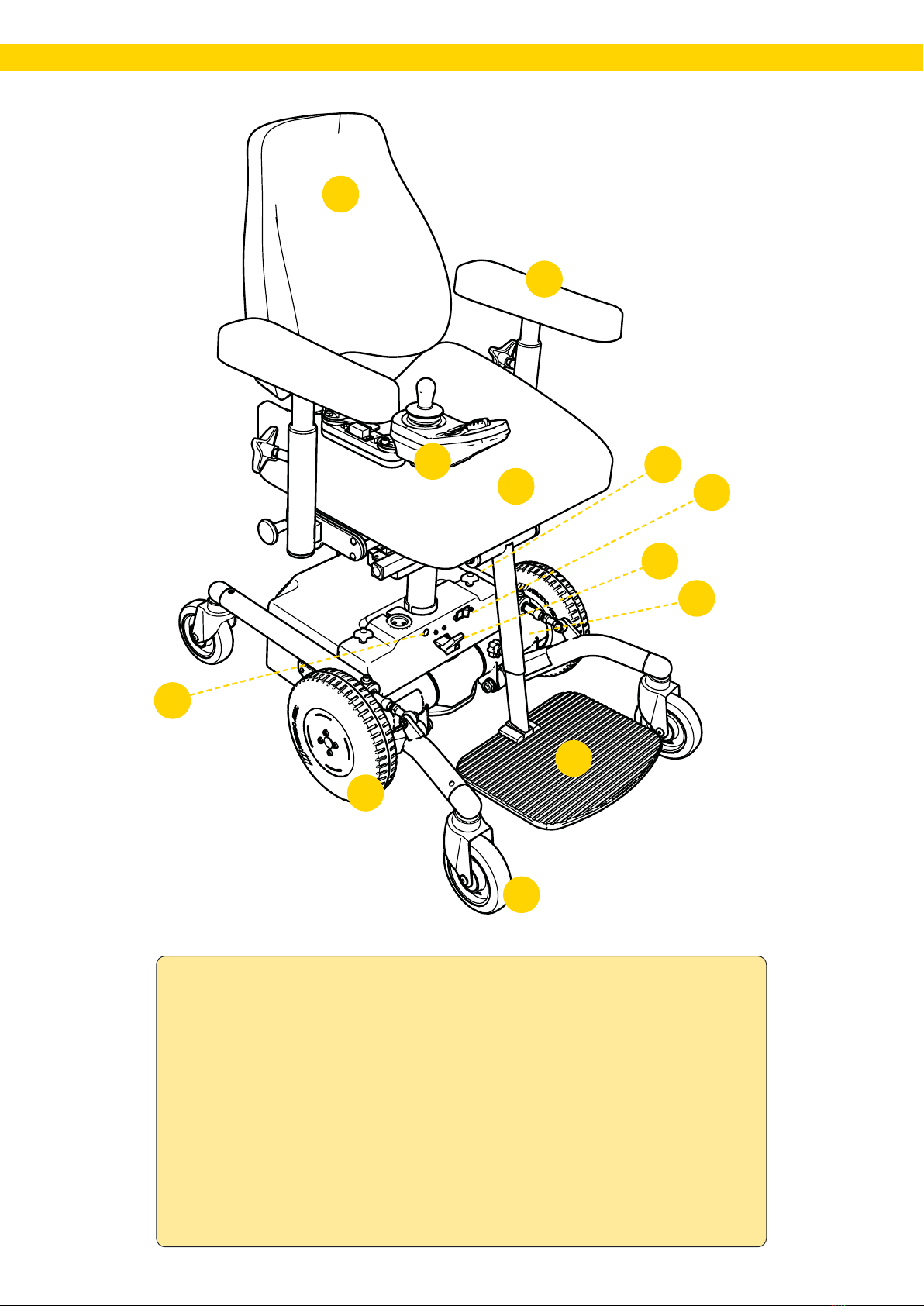
1. Electronics unit
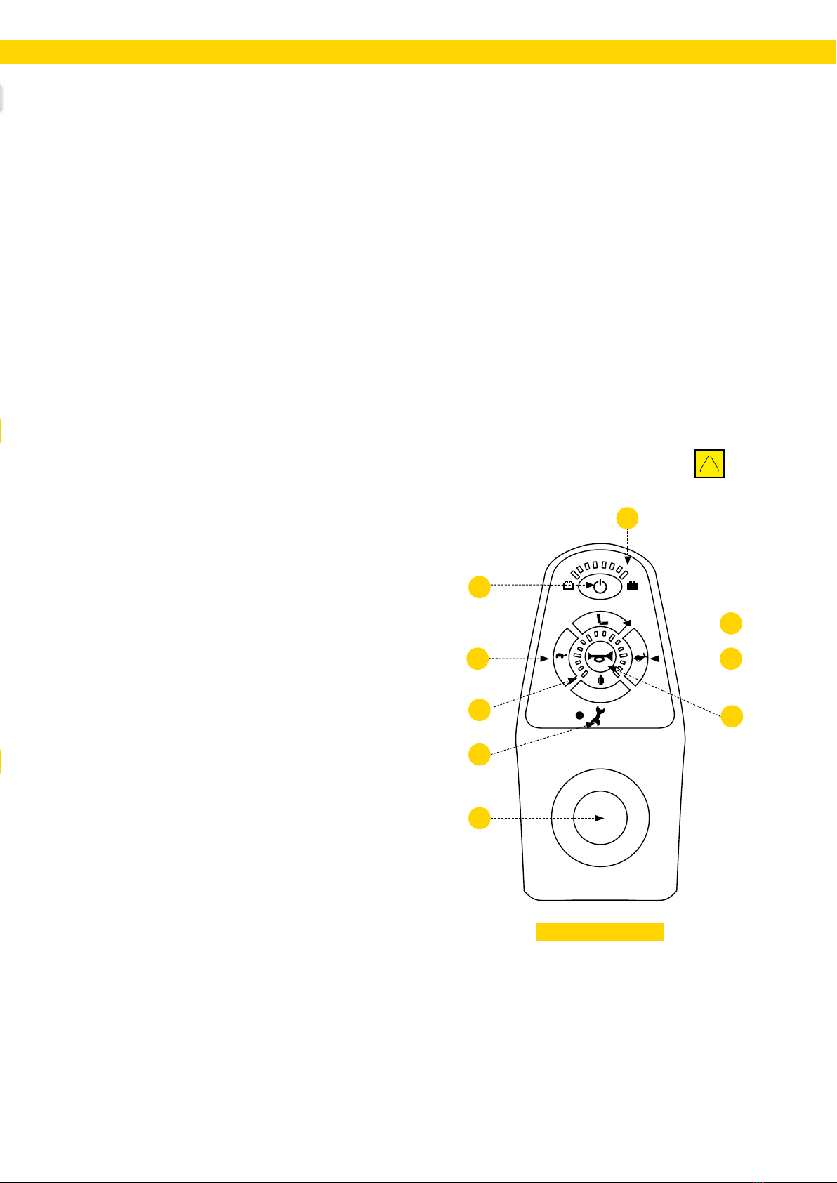
1.1. Electronics/function/cleaning
Connect the Wizard program and read
off the diagnostics. Check active errors
and diagnostics. Fix any errors and
reset the log.
1.2. Control unit/function/cleaning
Check the control unit functions, check
that the joystick bellows is intact and
that all buttons are working. Wipe
the control unit with a cloth lightly
dampened with disinfectant; this is to
avoid the risk of spreading infection.
Do not use solvents, bleach, polishes,
synthetic detergents, polishing waxes
or sprays on the chair.
1.3. Electrical seat functions (DCI)/
function
Check that plugged in electrical
functions are working and that the 12-
pin connector on the power module is
not loose or has any visible damage.
1.4. Connectors, attachment
Check that cables and connectors are
intact and properly secured. Make sure
that cables and connectors cannot be
pinched or crushed.
1.5. Batteries/battery charger/
function
Check that the charger is working
and that the housing and cables are
undamaged. Measure the battery
voltage and check that the difference
in battery charge level is not too great;
this indicates that a battery cell has
failed.
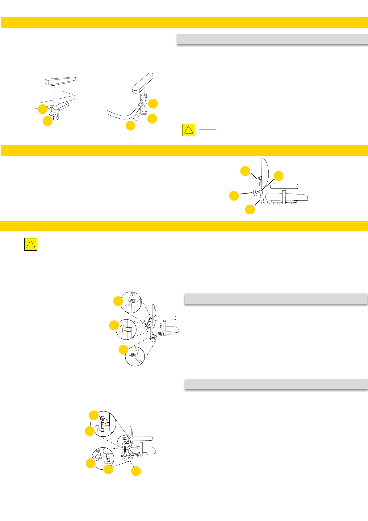
1.6. Electric seat tilt/function
Check that the actuator is not visibly
damaged. Check the function of the
actuator’s moving parts. Ensure that all
locking screws are tightened to avoid
any play in the end position.
1.7. Electric backrest/function
Check that the actuator is not visibly
damaged. Check the function of the
actuator’s moving parts. Ensure that all
locking screws are tightened to avoid
any play in the end position.
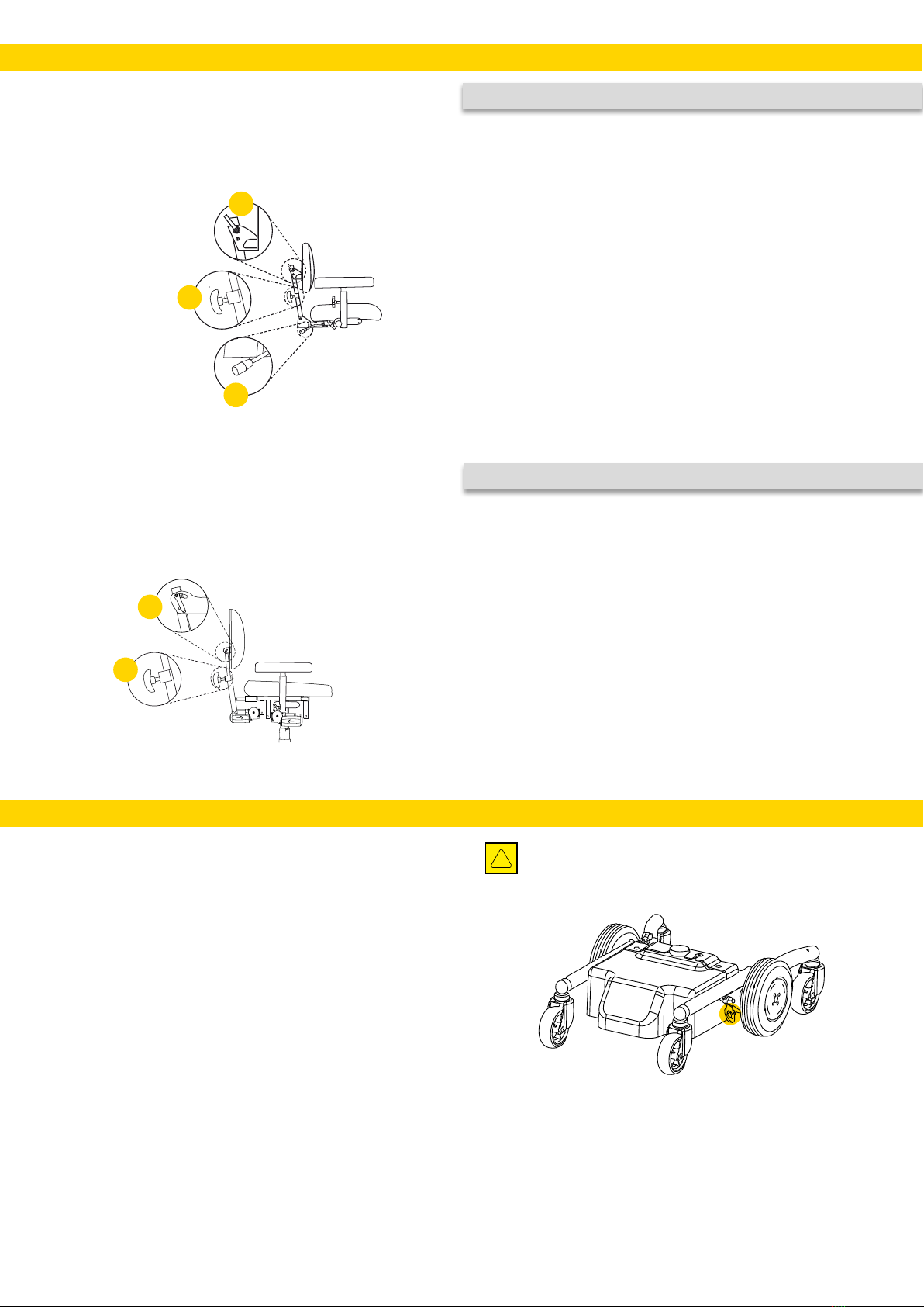
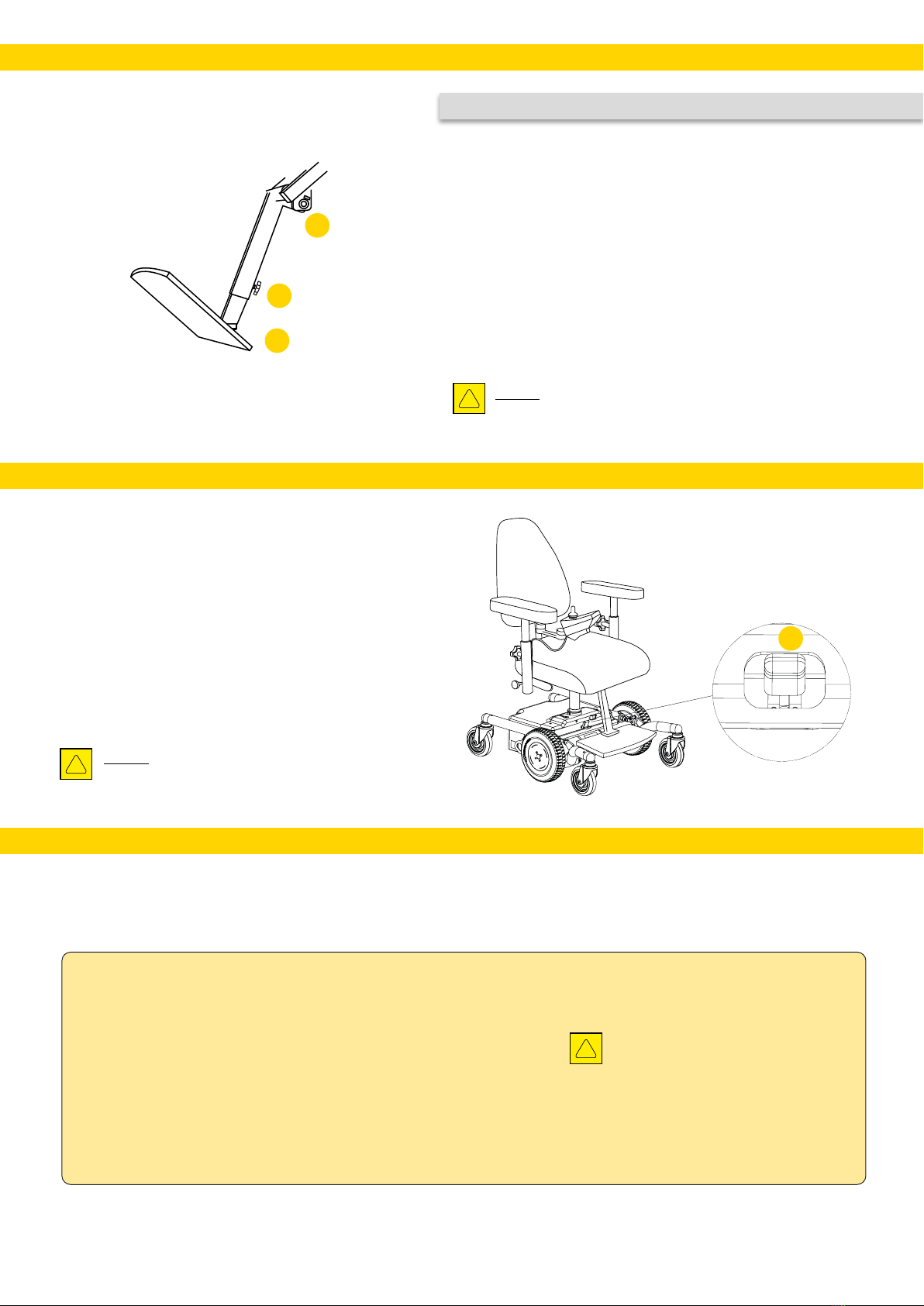
1.8. Electric leg support/function
Check that the actuator is not visibly
damaged. Check the function of the
actuator’s moving parts. Ensure that all
locking screws are tightened to avoid
any play in the end position. Check
all joints and that the lower clamping
bracket is securely tightened
2. Electric lifting mechanism
2.1. Noise / sliding clutch
Listen for any abnormal noise in
the gearbox bearings, and replace
the electric lifting mechanism if
a bearing is defective in any way.
The electric lifting mechanism can
be sent to Mercado Medic AB for
repair/reconditioning. Load the
chair and check that the electric
lifting mechanism does not slip in
its bottom position. If the electric
lifting mechanism slips, tighten the
safety clutch until the electric lifting
mechanism no longer slips.
2.2. Rotation lock / lubrication
Check that there is no play in the
electric lifting mechanism in the
direction of rotation. If there is, replace
the electric lifting mechanism. The
electric lifting mechanism can be
sent to Mercado Medic AB for repair/
reconditioning.
3.3. Attachment/tightening
Check that the attachments to the seat
frame and base are securely tightened.
4.4. Cabling/wear
Inspect cables for any signs of wear,
pinching or crushing.
3. Chassis
3.1. Welds
Check all welds carefully for signs of
cracks, corrosion, movement, etc.
3.2. Bolted joints
Check and tighten all bolted joints.
Replace screws that have damaged
heads or threads.
4. Drive wheels
4.1. Function/wear
Check that the drive wheels have good
tyre treads and that they have not
dried out (will result in poor friction to
the floor).
4.2. Bearings/wheel tracks
Check that the drive wheels are rolling
properly and that there is no play in the
motors’ gears.
4.3. Attachments/tightening
Remove the drive wheels and check
the motor screw joints. If necessary,
blow off all dust and dirt from the
motors.
5. Castors
5.1. Function / roll / swivel
Remove hair and dust from the castors
and check castors and castor housings
for wear and play, which may indicate
defective bearings. Check that the
castors swivel and the housings
rotate as expected. Replace castors if
necessary.
5.2. Attachment/tightening
Check that the castor screws are intact
and tightened.
6. Brake release
6.1. Function
Check that there is no play in the
brake release control and that the
magnet activates the sensor upon
disconnection. Make sure that the drive
wheels rotate easily when disengaged.
6.2. Setting/tightening
If the brake release does not properly
reconnect, adjust the brake release
mechanism.
CHECKLIST RECONDITIONING AND SERVICE REAL 6100 PLUS

1720-07457-UK-02
7. Seat frame
7.1. Mechanics/welds
Thoroughly inspect all welded
parts (especially when installing tilt
mechanisms, as these parts carry the
most load).
7.2. Screw joints/tightening
Check and tighten all screw joints.
Replace screws that have damaged key
handles or threads.
7.3. Plastic plugs / guide bushings
Make sure that guide bushings and
plastic plugs are properly secured, and
replace worn or damaged parts.
7.4. Seat/replacement/cleaning
Replace the seat with a new one and
wash or replace any covers
7.5. Operation/lubrication
Make sure that all knobs and levers on
the seat frame are working and that
they lock correctly.
7.6. Gas spring tilt/function
If the chair is equipped with a gas
spring tilt, check that this locks
securely and that there is no gradual
change in tilt when loaded. Check and
replace damaged wires and sheaths.
7.7. Crank tilt/wear
If the chair is equipped with crank tilt
controls, check that there is no play
and that all screws are tightened.
7.8. Coxit mechanism/operation
Make sure that the knobs for the flaps
turn easily and are securely locked
with the counter nut.
8. Backrest mechanism
8.1. Function/wear
Check and replace any worn parts,
and make sure that moving parts are
working correctly.
8.2. Attachment/tightening
Check that all screws, knobs and levers
lock properly and that the button clips
are working correctly.
8.3. Plastic plugs/guide bushings
Make sure that guide bushings and
plastic plugs are properly secured, and
replace worn or damaged parts.
8.4. Backrest/replacement/
cleaning
Replace the backrest with a new one
and wash or replace any covers
8.5. Gas spring lever/function
Check the gas pressure and stability
of the gas spring. Ensure that it locks
securely and that there is no gradual
change in the backrest angle when
loaded. Check and replace damaged
wires and sheaths.
9. Armrests
9.1. Function/wear
Check and replace any worn parts and
make sure that locking mechanisms
and moving parts are working correctly.
9.2. Plastic plugs/guide bushings
Make sure that guide bushings and
plastic plugs are properly secured, and
replace worn or damaged parts.
9.3. Armrest plates/replacement/
cleaning
Replace armrest plates with new ones.
9.4. Armrest mechanics/function
Check all welds and that there is no
damage to the tube system that may
impair or weaken the structure.
10. Accessories
10.1. Reset
Remove any accessories that are not
normally installed on the chair and
inspect them as detailed below before
potentially placing them in storage.
10.2. Mechanics
Inspect all welds and that there is no
damage to mechanical parts that may
impair or weaken the structure.
10.3. Function/wear
Check and replace any worn parts and
make sure that locking mechanisms
and moving parts are working correctly.
10.4. Padded parts
Discard padded parts so that they do
not pass on any infection. Discard or
wash covers according to washing
instructions.
11. Programming
Restore the application to its
default application. Make sure
that all logs are reset if the chair is
going to be turned over to another
user.
12. Test drive
Test drive the chair and ensure
that all electric functions, driving
programs and brakes work in
accordance with the standard
program. If the chair is to be
placed in storage, the main fuse
on the front side of the battery box
should be disconnected to save
battery consumption.
CHECKLIST RECONDITIONING AND SERVICE REAL 6100 PLUS, CONT.
Instructions for source separation of
components. The highest possible
component weight in kg (depends on
chair configuration) is specified for
each component.
Combustible:
• Seat (3.2 kg)
• Backrest (4 kg)
• Neck support (0.7 kg)
• Armrest (0.7 kg)
• Other padded parts sold by
Mercado Medic AB
Plastics:
• Covers are sorted for disposal in
accordance with markings on the
plastic. If there is no marking, sort
these as combustible.
Metal:
• Armrest mechanism (1.8 kg)
• Backrest mechanism (7.2 kg)
• Neck support mechanism (2.6 kg)
• Leg support (3.3 kg)
• Base (22.5 kg)
• Seat frame (7.7 kg)
• Actuator, tilt etc. (1.3 kg)
• Actuator up/down (3.6 kg)
• Gas spring for seat tilt (0.3 kg)
• Gas piston (3.2 kg)
• Other metal parts in products sold
by Mercado Medic AB
Electronic waste:
• Motors (3.2 kg)
• Cables (0.3 kg)
• Power module (0.9 kg)
• Joystick (0.4 kg)
• Actuator box (0.15 kg)
Lead battery:
• Batteries (9.7 kg/unit)
INSTRUCTIONS FOR DESTRUCTION


Mercado Medic AB Telephone & Fax E-mail & Internet
SE-181 57 Lidingö Fax +46 (0)8-555 143 99 Internet www.mercado.se
[Space for product label with serial number.]
GUIDELINES FOR INDIVIDUAL CUSTOMISATIONS OF
MERCADO MEDIC AB PRODUCTS
Customisations may only be carried out by authorised personnel who have completed Mercado Medic AB's
training programme for service and reconditioning. Parts that are on the list of current combination agreements
at www.mercado.se/mercado-dokument can be tted while retaining Mercado Medic AB’s CE marking. If a
desired item that is not on the list of current combination agreements is tted, the customer’s authorised personnel
must contact Mercado Medic AB for written approval.
Parts to be evaluated must be sent physically to Mercado Medic AB, either by the customer or the supplier of
the part in question. Mercado Medic AB will then contact the supplier of the part in question. If a combination
agreement is of interest, Mercado Medic AB will conduct a risk analysis on the desired part. Once the risk analysis
has been completed, the customer will receive a written statement.
Chairs that have been modied according to the following must be veried by Mercado Medic AB in order for
Mercado Medic AB to retain product liability.
• Padded parts (such as seats, backrests, armrests, side supports, trunk supports and neck supports) have been
adapted outside of the product’s existing external dimensions.
• e centre of gravity over lifting devices (must be retained/centred for optimum function) has been
changed.
• Padded parts that do not meet applicable ignitability requirements and/or other environmental
requirements have been used.
• Surfaces that are loaded with signicant vertical forces must not fall outside the area (base) that is formed
by the contact points of the castors against the oor.
If these guidelines are met, Mercado Medic AB retains the product liability for its product.
Products that are customised by health care services outside Mercado Medic AB’s directive, where health care
services also take over product liability, can be restored to their original condition. is must be carried out by an
authorised technician approved by Mercado Medic AB. Mercado Medic AB will then re-assume product liability
in accordance with the CE marking 93/42 EEC; Medical Devices Directive MDD.
If you have any questions regarding customisations/special adaptations, please contact Mercado Medic AB's
Product Manager, Ronny Fogelqvist:
Tel. +46 (0)708 27 96 14
E-mail ronny[email protected]
Other manuals for REAL 6100 PLUS
6
Table of contents
Other Mercado Medic Wheelchair manuals

Mercado Medic
Mercado Medic 805192 Assembly instructions

Mercado Medic
Mercado Medic REAL 6100 PLUS User manual

Mercado Medic
Mercado Medic REAL 9200 TWIN Use and care manual

Mercado Medic
Mercado Medic REAL 6100 PLUS User manual

Mercado Medic
Mercado Medic REAL 6100 PLUS Manual

Mercado Medic
Mercado Medic REAL 9000 PLUS Series Assembly instructions

Mercado Medic
Mercado Medic REAL 6100 PLUS User manual

Mercado Medic
Mercado Medic REAL 8200 PLUS SERIES Assembly instructions