Merck Millipore mA700 User manual
SigmaAldrich.com
20352498w Rev 03/20 1 of 9
Introduction
The mA700 Essential Power Supply is microprocessor
controlled and designed to meet most electrophoresis
needs. This manual describes the setup and operation
of the power supply, including important information
on safety and maintenance. The mA700 Essential Power
Supply can run horizontal & vertical electrophoresis,
SDS-PAGE, native PAGE, two-dimensional
electrophoresis, and electro-blotting.
The power supply offers access to 4 terminal pairs,
enabling use with multiple electrophoresis devices
simultaneously. The mA700 Essential Power Supply
provides constant voltage, constant current or constant
power.
Features of mA400 Basic Power Supply:
• Compact size
• Microprocessor controller
• Constant voltages, constant currents and constant
power
• Four terminal outlets
• LCD display
• Timer with alarm function
• Advanced safety devices
• Stackable
• Wide applications for DNA, RNA, and protein
electrophoresis
User Guide
mA700 Essential Power Supply
mA700
Introduction ....................1
Equipment Operation .............2
Symbols Used on Device
Regulatory
Warnings
Safety Precautions
Environmental Operating Conditions
Avoiding Electrical Shock
Avoiding Damage to the Instrument
Technical Specifications ...........3
Installation Instructions ..........4
Operating Instructions
Control Interface
Button Functions
General Operating Instructions .....5
Constant Mode Setup
Constant Mode Operation
Program Mode Setup
Program Mode Operation
Replacing the Fuse
Troubleshooting and Maintenance ...7
Product Ordering Information ......9
Support........................9
Notice
Contact Information
Legal Manufacturer
Technical Assistance
Standard Warranty
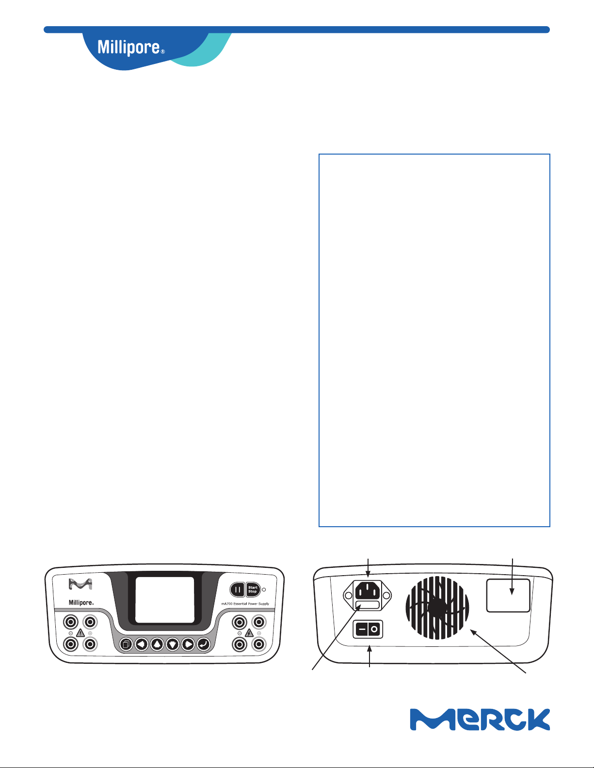
Back View
Front View
Main Power Socket
Fuse ON/OFF Switch
Label
Fan

20352498w Rev 03/20 2 of 9
Equipment Operation
Symbols Used on Device
The following symbols are used on this device,
throughout this user guide and/or on product labels,
and the user shall abide by indicated requirements.
Symbol Definition
Warning alerts you to actions that may cause
personal injury or pose a physical threat.
Indicates an area where a potential shock hazard
may exist. Consult the user guide to avoid possible
personal injury or instrument damage.
Do not discard with common solid waste at end
of life. Segregate with other waste electrical and
electronic equipment (WEEE) and send to an
appropriate facility for recycling. For information on
recycling electrical and electronic products in the
European Union, please visit
SigmaAldrich.com/weee.
Regulatory
The mA700 Essential Power Supply has been CE
marked to reflect compliance to the necessary
European Directives and NRTL (Nationally Recognized
Testing Laboratory) marked under the requirements of
OSHA (Occupational Safety and Health Organization)
for North America. For additional details into our
compliance claims, please refer to the product’s
web page online at SigmaAldrich.com. Search for
the product page, which shows the Declaration of
Conformity.
Warnings
The power supply unit generates, uses, and can radiate
radio frequency energy, and if not installed and used
in accordance with the user guide, may cause harmful
interference to radio communications. Operation of the
mA700 Essential Power Supply in a residential area
is likely to cause harmful interference in which case
the user will be required to correct the interference at
their expense. Changes or modifications not expressly
approved by the party responsible for compliance could
void the user’s authority to operate the equipment.
It is strongly recommended for the user to read
the following points carefully before operating this
equipment.
• Do not alter the equipment. Failure to follow these
directions could result in personal and/or laboratory
hazards, as well as invalidate equipment warranty.
• Use a properly grounded electrical outlet with
correct voltage and current handling capacity.
• Disconnect from power supply before maintenance
and servicing. Refer servicing to qualified
personnel.
• Never use this instrument series without having the
safety cover correctly in position.
• Do not use the unit if there is any sign of damage
to the external tank or cover. Replace damaged
parts.
• Do not use in the presence of flammable or
combustible material; fire or explosion may result.
This device contains components which may ignite
such materials.
• Refer maintenance and servicing to qualified
personnel.
• Ensure that the system is connected to electrical
service according to local and national electrical
codes. Failure to make a proper connection may
create fire or shock hazard.
Safety Precautions
Take a high level of precaution when using any
electrical device. Before connecting the electrical
supply, confirm that the supply voltage is within the
range stated on the rating label, and see that the
device is securely positioned. Place the unit in a safe
and dry location; it must NOT touch the surrounding.
Follow the safety precautions for chemicals / dangerous
materials.
1. NEVER access dangerous chemicals or other
materials to prevent possible hazard of explosion
and damage.
2. Do not operate the unit without lids or covers to
prevent possible hazards.
3. A temporary conductivity caused by condensation
might occur even though this series is rated
Pollution Degree 2 in accordance with IEC 664.
Environmental Operating Conditions
Ensure the instrument is installed and operated strictly
under the following conditions:
1. Indoor use only
2. < 95% Relative Humidity
3. 75 - 106 kPa
4. Altitude must not exceed 2000 meters
5. 4 - 40 °C operating temperature
6. Pollution degree: 2
7. Mains supply voltage must not fluctuate more than
±10% of the normal voltage

20352498w Rev 03/20 3 of 9
Avoiding Electrical Shock
Follow the guidelines below to ensure safe operation of
the unit.
The mA700 Essential Power Supply has been designed
to utilize shielded wires thus minimizing any potential
shock hazard to the user. We recommend against the
use of unshielded wires.
To avoid electrical shock:
1. In the event of solution spilling on the instrument,
it must be dried out for at least 2 hours and
restored to NORMAL CONDITION before each
operation.
2. Never connect or disconnect wires loading from the
power jacks when the red indicator light of power
switch is on.
3. WAIT at least 5 seconds after stopping a run
before handling output leads or any connected
apparatus.
4. ALWAYS make sure that your hands, work area,
and instruments are clean and dry before making
any connections or operating the power supply.
5. ONLY connect the power cord to a properly
grounded AC outlet.
Avoiding Damage to the Instrument
1. Do not attempt to operate the device if damage is
suspected.
2. Protect this unit from physical damage, corrosive
agents and extreme temperatures (direct sunlight,
etc.).
3. For proper ventilation and safety concerns, keep at
least 10 cm of space behind the instrument, and at
least 5 cm of space on each side.
4. Use high level of precaution against potential
damage on the unit.
5. Do not operate the unit out of environmental
conditions addressed above.
6. Do not operate the power supplies in high humidity
environments (> 95%), or where condensation may
occur.
7. To avoid condensation after operating the power
supply in a cold room, wrap the unit in a plastic bag
and allow at least 2 hours for the unit to equilibrate
to room temperature before removing the bag and
operating the unit.
8. Prior to applying any cleaning or decontamination
methods other than manufacturer’s
recommendation, users should check with the
manufacturer’s instruction to see if the proposed
method will damage the equipment.
Technical Specifications
Output Voltage/
Inc. 5-300 V / 1 V
Output Current/
Inc. 1-700 mA / 1 mA
Max. Output Watt 150 W
Rated Voltages 100 - 240 Vac, 50 / 60 Hz
200 W: T2.5A / 250 V
Type of Output
1. Voltage or Current with automatic
crossover.
2. When target constant mode is set,
system automatically adjusts the two
other parameters to maximum to allow
constant run (later could be changed by
user).
Program
Multi-Step Up to 6 steps
Editable Program
Function
1. Have typical running conditions
program
2. Manual editable program
Display 2.4” TFT
Control Microprocessor controller
Safety Device
No Load detect
Leakage detect
Over temperature protection
Overload detection
Sudden load change detection (could be
enabled by proper setting)
Shrouded plugs and sockets
Timer
Constant: 1-9999 mins with alarm,
continuous
Program: 1-999 mins with alarm,
continuous
Crossover Yes
Stackable Yes
Automatic
Recovery Yes
IQ/OQ Protocols Yes, optional
Operating
Temperature 4-40 °C
Construction
Material Flame-retardant ABS faceplate
Unit Dimension 215 mm x 335 mm x 104 mm
(W x L x H)
Weight Approx. 2.1 kg

20352498w Rev 03/20 4 of 9
Installation Instructions
1. Place the unit on a sturdy and level surface in a
safe dry place away from laboratory traffic.
2. Ensure that the power switch is OFF, and then plug
one end of the three-pronged power cord into a
grounded three-prong AC outlet with appropriate
voltage (100 V to 240 V, as indicated on the rating
sticker near the AC cord on the back of the unit)
and plug the other end into the main power socket.
Power Switch
3. Connect the DC output jacks from the
electrophoresis unit; insert the red lead (+) into
the red output jack, and the black lead (-) into
the blue output jack.
4. Power ON the unit by pressing the ON / Off switch
on the back.
Operating Instructions
Control Interface
LED Indicator
Indicates running
conditions
Button Functions
Key
Descriptions
Icon Function
Start
Stop Press to activate or stop the unit.
Pause
Press to temporarily interrupt power to an
operation in progress; resume power after
pausing without resetting the timer.
Page
Toggle Press to go back to previous page.
Enter 1. Press to enter the next page.
2. Press to enable numeric set-up.
Left
Arrow
Press to move cursor left forward between
parameters.
Right
Arrow
Press to move cursor right forward
between parameters.
Up
Arrow
1. Press to move cursor up between
parameters.
2. Press to increase numeric values.
Down
Arrow
1. Press to move cursor down between
parameters.
2. Press to decrease numeric values.
Plugs
20352498w Rev 03/20 5 of 9
General Operating Instructions
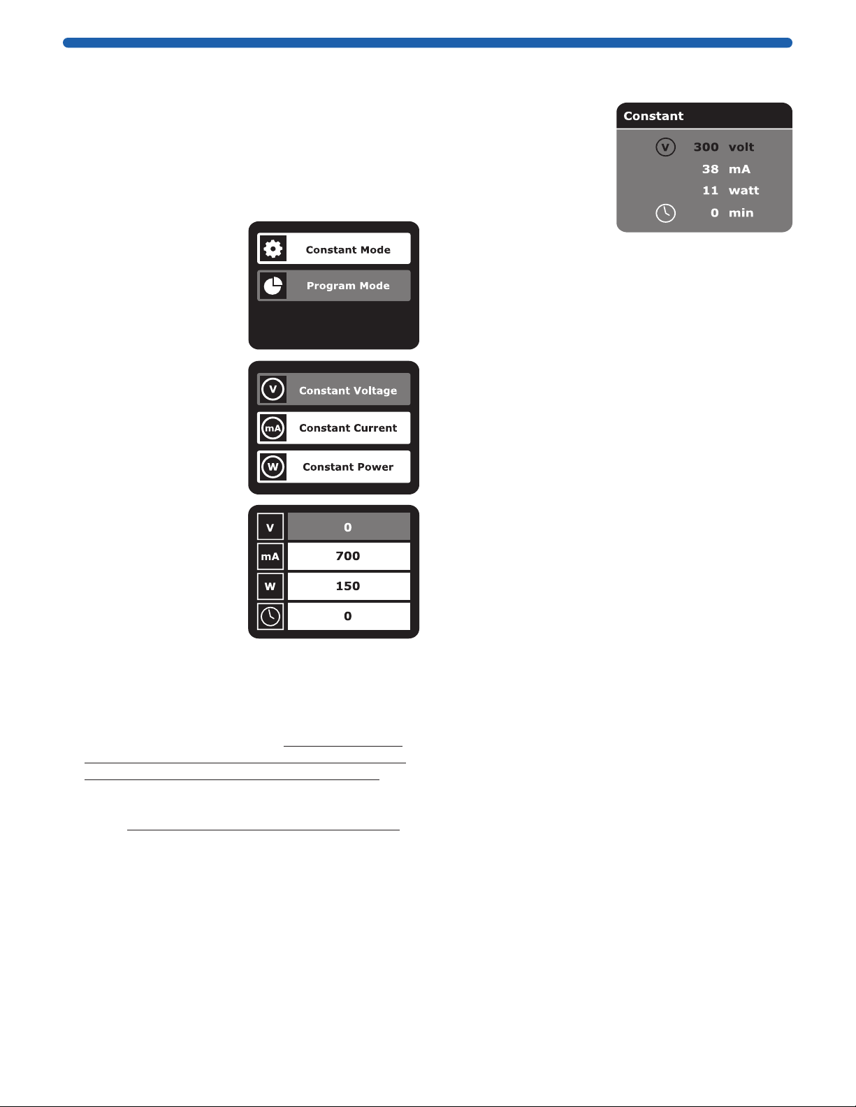
There are 2 modes available: Constant Mode, and
Program Mode.
Constant Mode Setup
Use the Constant Mode for applications that require
only one specific limit: voltage / current / power during
the entire operation of electrophoresis.
1. Use the Up and Down
arrow keys to select
the Constant Mode
button. Use the Enter
key to select.
2. Use the Up or Down
arrow keys to select
any of:
> Constant Voltage (V)
> Constant Current (mA)
> Constant Power (W)
3. Use the Enter key to
select.
4. Use the Up or Down
arrow keys to toggle
between
> Voltage (V)
> Current (mA)
> Power (W)
> Time (minutes)
5. Use the Enter key to
select the specified
parameter to set target value.
6. Use the Up or Down arrow keys to adjust the value
for the selected parameter. Use the Enter key to set
value.
Note: Under Constant Mode, when target value
is set, system automatically adjusts the other two
parameters to maximum to allow constant run. For
example, if constant voltage (V) is set, system will
adjust current (mA) and power (W) to the maximum
value. User could later lower the other two values.
System will hold the value either at the target
constant value or the one which has been reached
first. If the time value is set to “0,” it means infinite,
and the power supply will constantly operate until
the user manually ends the run.
Constant Mode Operation
1. Press the Start
Stop key to start
operation. The LED
is lit, and the screen
will show real-time
parameter values.
When parameter
reaches the set value,
its color will turn
orange.
2. Press the Toggle key to switch the display between
real-time value and set value page.
Note: When a run is completed, operation stops with
an alarm, and COMPLETE is displayed on the screen.
3. Press the Start Stop key to terminate the run.
4. Turn the power off by using the switch on the back
before removing the power leads.
Note: It takes approximately 5 seconds for the unit
to power off.
5. Press the Pause key to temporarily pause the
ongoing run without terminating the timer. The
LED will flash to indicate that the run is paused.
Press the Start Stop key to resume the run.
6. Press the Start Stop key to terminate the run.
To modify any parameters during the operation
(without terminating the timed run), pause the run
by pressing the Pause key.
7. Press the Toggle key to enter the Settings page.
8. Adjust the desired parameter and then press the
Start Stop key to resume the run.
9. To terminate and start a new run during operation,
press the Start Stop key instead of the Pause key.
10. After adjusting the parameters, press the Start
Stop key again to start a new run.
Note: To terminate and start a new run, the timer
will reset and does not take into account the time
before.

20352498w Rev 03/20 6 of 9
Program Mode Setup
Use the Program Mode to vary levels in voltage
(V), current (mA), and power (W) during specified
time periods for up to 6 Steps, depending upon your
electrophoresis needs. The mA700 Essential Power
Supply will store up to 30 different program files stored
for user’s convenience. Follow the instructions below to
set the Program Mode.
1. Use the Up and Down
arrow keys to select
Program Mode.
Use the Enter key to
select.
2. Use the Up and Down
arrow keys to select
the appropriate file
number, then press
the Enter key to
select.
3. Use the Up or Down
arrow keys to toggle
between
> Voltage (V)
> Current (mA)
> Power (W)
> Time (minutes)
4. Use the Enter key to
select the specified
parameter to set
target value.
5. Use the Enter key
and the Up and Down
arrow keys to set the appropriate values, then
press the Enter key to set. Repeat this step until all
the parameters are set properly. There are 6 steps
available.
Note: If the time value is set to “0” at any stage, it
means stop at previous stage. For example, if Stage
1 is set to 5 minutes and Stage 2 is set to “0,” the
system will only complete Stage 1 and stop.
Program Mode Operation
1. Press the Start Stop
key to start operation.
The LED is lit, and
the screen will show
real-time parameter
values. When
parameters reach the
set value, the color
will turn orange.
2. Press the Toggle key to switch the display between
real-time value and set value page.
Note: When a run is completed, operation stops
with an alarm and COMPLETE is displayed on the
screen.
3. Press the Start Stop key to terminate the run.
4. Turn off the power using the back switch before
removing the Power Leads.
Note: It takes approximately 5 seconds for the unit
to power off.
5. Press the Pause key to temporarily pause the
ongoing run without terminating the timer. The LED
will flash to indicate that the run is paused. Press
the Start Stop key to resume the run.
6. Press the Start Stop key to terminate the run.
To modify any parameters during the operation
(without terminating the timed run), pause the run
by pressing the Pause key.
7. Press the Toggle key to enter the Settings page.
8. Adjust the parameter and then press the Start Stop
key to resume the run.
9. To terminate and start a new run during operation,
press the Start Stop key instead of the Pause key.
10. After adjusting the desired parameters, press the
Start Stop key again to start a new run.
Note: If the run has been terminated, and a new
one started, the timer will reset and does not take
into account the time before.
20352498w Rev 03/20 7 of 9
Replacing the Fuse
1. Turn off the main power switch at the rear of
Power Supply and detach the power cord.
2. Open the fuse compartment located at the Main
Power Socket by inserting a small flat blade
screwdriver into the slot below the ON/OFF switch.
Turn the screwdriver to gently pry open the fuse
compartment.
Note: The fuse compartment will not open with the
power cord in place.
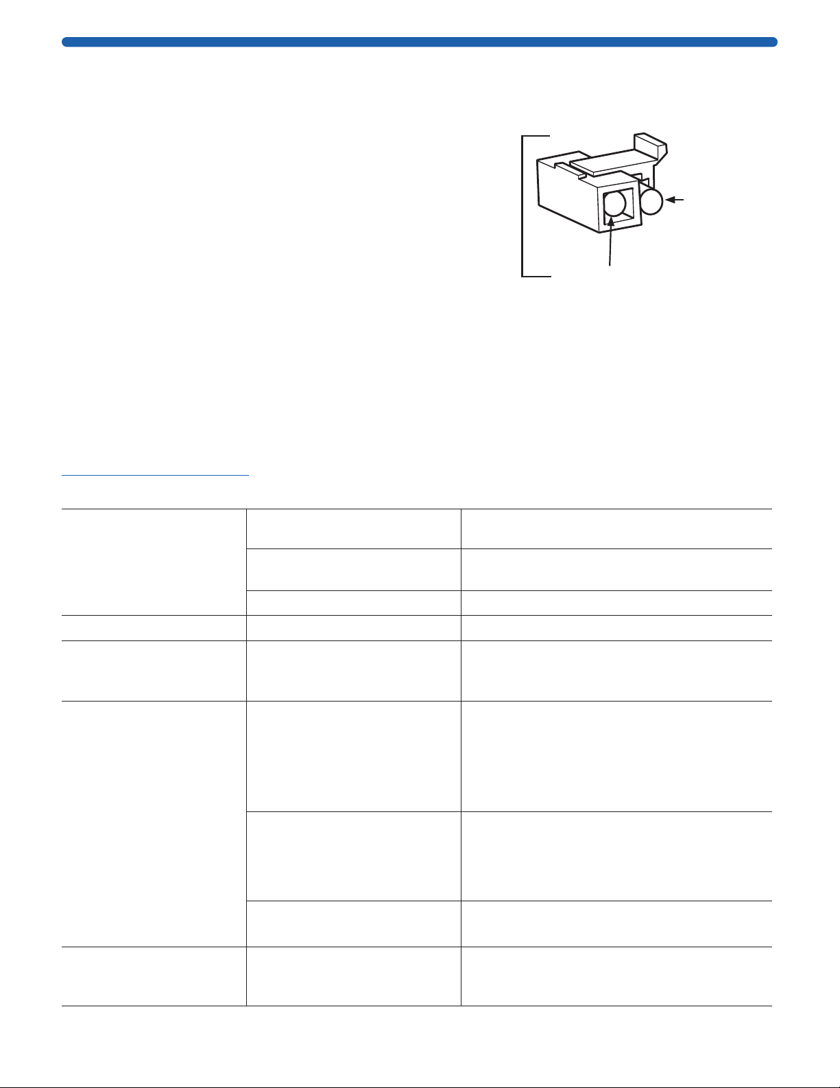
3. Pull the fuse holder out of the compartment and
inspect the fuse. If the fuse is burned or there is a
break in the fuse element, replace the fuse with an
identical type of fuse (T2.5AH250V) as provided in
the fuse holder
(see figure right).
4. Place the fuse holder back into the compartment.
5. Snap the cover closed.
Troubleshooting and Maintenance
Many operating problems may be solved by carefully reading and following the instructions in this manual
accordingly. Should these suggestions not resolve the problem, visit the Technical Service at
SigmaAldrich.com/techservice.
Problem Possible Causes Solution
No display or lights.
No AC power. Check if power supply is plugged in,
or if AC power source has problem.
AC power cord is not connected. Check the AC power cord connections
at both ends. Use the correct cords.
The fuse has blown. Replace the fuse.
Fuse broken repeatedly. Hardware failure. Contact our Technical Service Department.
Operation stops and
the screen displays
PLC ERROR.
Communication wires on circuit
board have loosened or broke.
We recommend that you send the machine
back to your local distributor or our Technical
Service Department for maintenance.
Operation stops with alarm.
The screen displays
NO LOAD.
Electrophoresis leads are not
connected to the power supply
or to the electrophoresis unit(s),
or there is a broken circuit in
the electrophoresis cell.
Check the connections to the power supply and
on your electrophoresis cell to make sure the
connection is intact; check condition of wires
in electrophoresis unit. Close the circuit by
reconnecting the cables. Press
START / STOP to restart the run.
High resistance due to tape
left on a pre-cast gel, incorrect
buffer concentration, or
incorrect buffer volumes in the
electrophoresis cell
Make sure the tape is removed from the
pre-cast gel, buffers are prepared correctly, and
the recommended volume of buffer is added to
the electrophoresis unit.
High voltage application is set to
run on a very low current.
DISABLE the No Load alarm on the Display
Screen.
Operation stops with alarm.
Display shows:
LOAD CHANGED.
Bad connections for terminal
connectors or damaged wires or
damaged platinum wires.
Check all the connections to terminators,
cables, wires, and gel tanks.
Fuse in Use
Extra Fuse
Fuse Holder

20352498w Rev 03/20 8 of 9
Problem Possible Causes Solution
Operation stops with alarm.
Display shows:
OVER VOLTAGE.
Circuit is interrupted.
Verify that the running buffer is correct.
Verify that all cables are attached correctly.
Turn the Power switch off and on again; restart
application.
If you cannot restart the instrument, turn off
the power, disconnect the power cord from the
outlet, and contact Technical Service.
Operation stops with alarm.
Display shows:
OVER CURRENT.
Circuit is interrupted.
Verify that the running buffer is correct.
Verify that all cables are attached correctly.
Turn the Power switch off and on again; restart
application.
If you cannot restart the instrument, turn off
the power, disconnect the power cord from the
outlet, and contact Technical Service.
Operation stops with alarm.
Display shows: LEAKAGE.
Ground leak detected during
run.
Check the electrophoresis system for improper
grounding. Restart the power supply by turning
the Power switch off and on.
Operation stops with alarm.
Display shows:
OVER TEMPERATURE.
Power supply is overheating.
Turn off power supply. Check for sufficient
airflow around the power supply fan. After
cooling down, restart the power supply by
turning the Power switch to the on position.
If you cannot restart the instrument, turn off
the power, disconnect the power cord from the
outlet, and contact Technical Service.
Warning message displays
with 5-second beeping
sound. Display shows:
POWER RECOVERY.
The power that had been cut
has now recovered.
User does not need to take extra action. The
warning sign and beep sound would only last
for 5 second; after that, the machine will
continue running the unfinished project.
The sign indicates that the machine has
been interrupted by sudden power off. Press
the ENTER key to clear the sign.

20352498w Rev 03/20 9 of 9
The life science business of Merck operates
as MilliporeSigma in the U.S. and Canada.
Merck, Millipore and Sigma-Aldrich are trademarks of Merck KGaA, Darmstadt, Germany or its
affiliates. All other trademarks are the property of their respective owners. Detailed information
on trademarks is available via publicly accessible resources.
© 2020 Merck KGaA, Darmstadt, Germany and/or its affiliates. All Rights Reserved.
Product Ordering Information
The mA700 can be purchased with different power
supply cords to accomodate a variety of locations.
Purchase products online at SigmaAldrich.com/products.
Model Description Catalog
Number
mA700
Essential
Power
Supply
mA700 Power Supply with cord for
the US, Canada, and locations
using NEMA 5-15P (YP12) plugs
MA700-US
mA700 Power Supply with cord for
France, Germany, and locations
using CEE 7/7 (YP22) plugs
MA700-EU
mA700 Power Supply with cord for
the UK, Ireland and locations using
type G (YP61) plugs
MA700-UK
mA700 Power Supply with cord for
Japan and locations using YP18
plugs
MA700-NI
mA700 Power Supply with cord for
China and locations using Type I
(YP03) plugs
MA700-ZH
Also available
mA400
Basic
Power
Supply
mA400 Power Supply with cord for
the US, Canada, and locations
using NEMA 5-15P (YP12) plugs
MA400-US
mA400 Power Supply with cord for
France, Germany, and locations
using CEE 7/7 (YP22) plugs
MA400-EU
mA400 Power Supply with cord for
the UK, Ireland, and locations
using type G (YP61) plugs
MA400-UK
mA400 Power Supply with cord for
Japan and locations using YP18
plugs
MA400-NI
mA400 Power Supply with cord for
China and locations using Type 1
(YP03) plugs
MA400-ZH
Support
Notice
We provide information and advice to our customers
on application technologies and regulatory matters
to the best of our knowledge and ability, but without
obligation or liability. Existing laws and regulations are
to be observed in all cases by our customers. This also
applies in respect to any rights of third parties. Our
information and advice do not relieve our customers of
their own responsibility for checking the suitability of
our products for the envisaged purpose.
The information in this document is subject to change
without notice and should not be construed as a
commitment by the manufacturing or selling entity, or
an affiliate. We assume no responsibility for any errors
that may appear in this document.
Contact Information
For the location of the office nearest you, go to
SigmaAldrich.com/offices.
Legal Manufacturer
EMD Millipore Corporation
400 Summit Drive, Burlington, MA, USA
Technical Assistance
Visit the tech service page on our web site at
SigmaAldrich.com/techservice.
Standard Warranty
The applicable warranty for the products listed in this
publication may be found at SigmaAldrich.com/terms.
Table of contents


