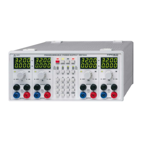
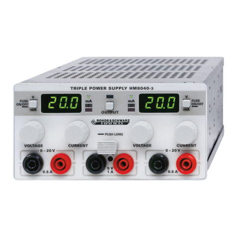
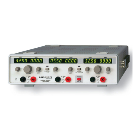
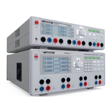
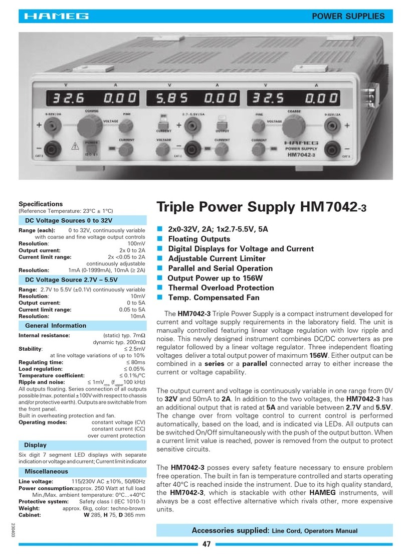
Hameg HM7044 User manual

14 Subject to change without notice
General remarks regarding the CE marking
KONFORMITÄTSERKLÄRUNG
DECLARATION OF CONFORMITY
DECLARATION DE CONFORMITE
DECLARACIÓN DE CONFORMIDAD
Hersteller / Manufacturer / Fabricant / Fabricante:
HAMEG Instruments GmbH · Industriestraße 6 · D-63533 Mainhausen
Die HAMEG Instruments GmbH bescheinigt die Konformität für das Produkt
The HAMEG Instruments GmbH herewith declares conformity of the product
HAMEG Instruments GmbH déclare la conformite du produit
HAMEG Instruments GmbH certifica la conformidad para el producto
Bezeichnung / Product name / Programmierbares-Netzgerät
Designation / Descripción: Progammable Power Supply
Alimentation programmable
Alimentación programable
Typ / Type / Type / Tipo: HM7044
mit / with / avec / con: –
Optionen / Options /
Options / Opciónes: –
mit den folgenden Bestimmungen / with applicable regulations /
avec les directives suivantes / con las siguientes directivas:
EMV Richtlinie 89/336/EWG ergänzt durch 91/263/EWG, 92/31/EWG
EMC Directive 89/336/EEC amended by 91/263/EWG, 92/31/EEC
Directive EMC 89/336/CEE amendée par 91/263/EWG, 92/31/CEE
Directiva EMC 89/336/CEE enmendada por 91/263/CEE, 92/31/CEE
Niederspannungsrichtlinie 73/23/EWG ergänzt durch 93/68/EWG
Low-Voltage Equipment Directive 73/23/EEC amended by 93/68/EEC
Directive des equipements basse tension 73/23/CEE amendée par 93/68/CEE
Directiva de equipos de baja tensión 73/23/CEE enmendada por 93/68/EWG
Angewendete harmonisierte Normen / Harmonized standards applied /
Normes harmonisées utilisées / Normas armonizadas utilizadas:
Sicherheit / Safety / Sécurité / Seguridad:
EN 61010-1: 1993 / IEC (CEI) 1010-1: 1990 A 1: 1992 / VDE 0411: 1994
Überspannungskategorie / Overvoltage category / Catégorie de surtension /
Categoría de sobretensión: II
Verschmutzungsgrad / Degree of pollution / Degré de pollution /
Nivel de polución: 2
Elektromagnetische Verträglichkeit / Electromagnetic compatibility /
Compatibilité électromagnétique / Compatibilidad electromagnética:
EN 61326-1/A1: Störaussendung / Radiation / Emission:
Tabelle / table / tableau 4; Klasse / Class / Classe / classe B.
Störfestigkeit / Immunity / Imunitee / inmunidad:
Tabelle / table / tableau / tabla A1.
EN 61000-3-2/A14: Oberschwingungsströme / Harmonic current emissions /
Émissions de courant harmonique / emisión de corrientes armónicas: Klasse /
Class / Classe / clase D.
EN 61000-3-3: Spannungsschwankungen u. Flicker / Voltage fluctuations and
flicker / Fluctuations de tension et du flicker / fluctuaciones de tensión y flicker.
Datum / Date / Date / Fecha
15.09.2004
Unterschrift / Signature / Signatur / Signatura
M. Roth
Manager
General remarks regarding the CE marking
HAMEG measuring instruments comply with the EMI norms. Our tests
for conformity are based upon the relevant norms. Whenever different
maximum limits are optional HAMEG will select the most stringent
ones. As regards emissions class 1B limits for small business will be
applied. As regards susceptability the limits for industrial environments
will be applied.
All connecting cables will influence emissions as well as susceptability
considerably. The cables used will differ substantially depending on the
application. During practical operation the following guidelines should
be absolutely observed in order to minimize EMI:
1. Data connections
Measuring instruments may only be connected to external associated
equipment (printers, computers etc.) by using well shielded cables.
Unless shorter lengths are prescribed a maximum length of 3 m must
not be exceeded for all data interconnections (input, output, signals,
control). In case an instrument interface would allow connecting several
cables only one may be connected.
In general, data connections should be made using double-shielded
cables. For IEEE-bus purposes the double screened cable HZ72 from
HAMEG is suitable.
2. Signal connections
In general, all connections between a measuring instrument and the
device under test should be made as short as possible. Unless a shorter
length is prescribed a maximum length of 3 m must not be exceeded,
also, such connections must not leave the premises.
All signal connections must be shielded (e.g. coax such as RG58/U).
With signal generators double-shielded cables are mandatory. It is
especially important to establish good ground connections.
3. External influences
In the vicinity of strong magnetic or/and electric fields even a careful
measuring set-up may not be sufficient to guard against the intrusion
of undesired signals. This will not cause destruction or malfunction of
HAMEG instruments, however, small deviations from the guaranteed
specifications may occur under such conditions.
HAMEG Instruments GmbH

15
Subject to change without notice
Deutsch 2
Français 27
Español 38
English
General remarks regarding the CE marking 14
Pogrammable Power Supply HM7044 16
Specifications 17
Important hints 18
Used symbols 18
Unpacking 18
Positioning 18
Transport 18
Storage 18
Safety instructions 18
Proper operating conditions 18
Warranty and repair 19
Maintenance 19
Mains voltage 19
Changing the line fuse 19
Operating controls 20
Introduction to the operation of HM7044 21
First time operation 21
Power on 21
Setting the parameters 21
1. Selecting the channels 21
2. Setting of the nominal value of the output voltage 21
3. Setting of the current limit 22
Electronic fuse 22
Tracking function 22
Connecting the load 23
Parallel and series operation 23
Activating the outputs 23
Remote Control 24
General 24
Command reference 24
Table of content
Test Equipment Depot - 800.517.8431 - 99 Washington Street Melrose, MA 02176
FAX 781.665.0780 - TestEquipmentDepot.com

16 Subject to change without notice
4x 0…32V/0…3 A
Up to 384W output power, pre-regulation with DC/DC converter
ensures low dissipated power
4-digit displays for current and voltage
Display resolution 10mV/1mA
Parallel (up to 12A) and Series (up to 128V) operation
Floating, overload and short-circuit proof outputs
Low residual ripple due to linear inline regulators
Tracking mode for all outputs
Adjustable current limiting and electronic fuse for each output
Possibility to link the fuses of several channels
SENSE lines for each output for compensation of the voltage
drop across the cables
Galvanically isolated USB/RS-232 Interface, optional IEEE-488
in HM7044G
Quadruple High-Performance
Power Supply
HM7044
HM7044
Silicone test cable HZ10
HO880 IEEE-488 (GPIB)
Interface (Option)
HM7044

17
Subject to change without notice
Quadruple High-Performance Power Supply HM7044
All data valid at 23 °C after 30 minute warm-up
Identical specifications for outputs 1, 2, 3 and 4
Constant voltage source
Voltage setting: 0…32 V DC
Resolution: 10 mV, 4-digit display
Setting accuracy: ±5digit
Ripple and noise: ‹1mV
rms voltage regulation
Current setting: 5mA…3A
Resolution: 1 mA, 4-digit display
Setting accuracy: ± 8 digit
Ripple and noise: ‹1mV
rms/ 100 μA current regulation
Parallel operating mode
Output voltage: 32 V max.
Output current: 12 A max. with four outputs
Output power: 384 W max.
Serial operating mode
Output voltage: 128 V max. with four outputs
Output current: 3 A max.
Output power: 384 W max.
Tracking mode
Voltage tracking with up to 4 outputs
Electronic fuse
Current setting: 5 mA…3A; fuse selectable for each output
Number of fuses: 4
Programmable output deactivation
On overcurrent at one output, up to four outputs can be disconnected
from load.
Output deactivation
All outputs can be activated/deactivated separately or together by
pressing a key.
7-segment displays
Eight displays, 4-digit voltage and current display
LED indicators
Output activated, current limit activated, fuse activated
(3 LEDs per output)
Interface
Interface: USB/RS-232 (HO820), IEEE-488 (option)
Command - processing time: 100ms until output voltage reaches the
digitally transmitted level
General information
Interior resistance
static: typ. 2.5 mΩ
dynamic: typ. 150 mΩ
10 / 90 % load settling time (constant voltage ± 100 mV):
≤2.5 ms
Stability: 0.1 mV at line voltage variation of up to
± 10 % at ‹ 80 W per output
Temperature coefficient: 100ppm/°C
Overcurrent cut-off time (› 3 A…0 A): ‹ 50 μs
DC floating outputs: max. ±150 V to chassis ground
Safety class: Safety class I (EN61010-1)
Power supply: 115/230 V~ ± 10 %, 50/60 Hz, CAT II
Power consumption: max. 530 W at 384 W power output
Operating temperature: +5°C...+40°C
Storage temperature: -20°C...+70°C
Max. rel. humidity: 5%...80% (non condensing)
Dimensions (W x H x D):285 x 125 x 365 mm
Weight: approx. 8.5 kg
Accessories supplied: Operator’s Manual and power cable
Optional accessories: HZ10S/R Silicone test lead, HZ43 19’’ Rackmount Kit 3RU,
HO880 IEEE-488 (GPIB) Interface (galvanically isolated)
HM7044E/130109/ce · Subject to alterations · © HAMEG Instruments GmbH®· DQS-certified in accordance with DIN EN ISO 9001:2000, Reg.-No.: DE-071040 QM
HAMEG Instruments GmbH · Industriestr. 6 · D-63533 Mainhausen · Tel +49 (0) 6182 800 0 · Fax +49 (0) 6182 800 100 · www.hameg.com · info@hameg.com
www.hameg.com
Specifications
USB/RS-232, optional: IEEE-488 (HO880)
Accessories supplied:
Power Supply HM7044, Operators Manual, Power cable, Product-CD
Optional accessories: HZ10S/R Silicone test lead, HZ43 19’’ Rackmount Kit 3
RU,HO880 IEEE-488 (GPIB) Interface

18 Subject to change without notice
picture 3
picture 2
picture 1
Important hints
(1) (2) (3) (4) (5)
Symbols
Symbol 1: Attention, please consult manual
Symbol 2: Danger! High voltage!
Symbol 3: Ground connection
Symbol 4: Important note
Symbol 5: Stop! Possible instrument damage!
Unpacking
Please check for completeness of parts while unpacking. Also
check for any mechanical damage or loose parts. In case of
transport damage inform the supplier immediately and do not
operate the instrument.
Positioning
Two positions are possible: According to picture 1 the front
feet are used to lift the instrument so its front points slightly
upward. (Appr. 10 degrees)
If the feet are not used (picture 2) the instrument can be com-
bined with many other HAMEG instruments.
In case several instruments are stacked (picture 3) the feet rest
in the recesses of the instrument below so the instru-ments
can not be inadvertently moved. Please do not stack more than
3 instruments. A higher stack will become unstable, also heat
dissipation may be impaired.
Transport
Please keep the carton in case the instrument may require
later shipment for repair. Losses and damages during trans-
port as a result of improper packaging are excluded from
warranty!
Storage
Dry indoors storage is required. After exposure to extreme tem-
peratures 2 h should held off on turning the instrument on.
Safety instructions
The instrument conforms to VDE 0411/1 safety standards
applicable to measuring instruments and left the factory in
proper condition according to this standard. Hence it conforms
also to the European standard EN 61010-1 resp. to the inter-
national standard IEC 61010-1. Please observe all warnings
in this manual in order to preserve safety and guarantee
operation without any danger to the operator. According to
safety class 1 requirements all parts of the housing and the
chassis are connected to the safety ground terminal of the
power connector. For safety reasons the instrument must only
be operated from 3 terminal power connectors or via isolation
transformers. In case of doubt the power connector should be
checked according to DIN VDE 0100/610.
Do not disconnect the safety ground either inside
or outside of the instrument!
– The line voltage of the instrument must correspond to the
line voltage used.
– Opening of the instrument is allowed only to qualified
personnel
– Prior to opening the instrument must be disconnected from
the line and all other inputs/outputs.
In any of the following cases the instrument must be taken out
of service and locked away from unauthorized use:
– Visible damages
– Damage to the power cord
– Damage to the fuse holder
– Loose parts
– No operation
– After longterm storage in an inappropriate environment ,
e.g. open air or high humidity.
– Excessive transport stress
Exceeding 42 V
By series connecting all outputs the 42 V limit can
be exceeded which means that touching live parts
may incur danger of life! It is assumed that only
qualified and extensively instructed personnel
are allowed to operate this instrument and/or the
loads connected to it.
Proper operating conditions
The instruments are destined for use in dry clean rooms.
Operation in an environment with high dust content, high hu-
midity, danger of explosion or chemical vapors is prohibited.
Operating temperature is +5 °C ... +40 °C. Storage or transport
limits are –20 ... +70 °C. In case of condensation two hours are
to be allowed for drying prior to operation. For safety reasons
Important hints
STOP
STOP
STOP

19
Subject to change without notice
operation is only allowed from 3 terminal connectors with
a safety ground connection or via isolation transformers of
class 2. The instrument may be used in any position, however,
sufficient ventilation must be assured as convection cooling is
used. For continuous operation prefer a horizontal or slightly
upward position using the feet.
STOP
Do not cover either the holes of the case nor the
cooling fins.
Specifications with tolerances are valid after a 30 minute
warm-up period and at 23 degrees C. Specifications without
tolerances are typical values of an average instrument.
Warranty and Repair
HAMEG instruments are subjected to a strict quality control.
Prior to leaving the factory, each instrument is burnt-in for
10 hours. By intermittent operation during this period almost
all defects are detected. Following the burn-in, each instru-
ment is tested for function and quality, the specifications are
checked in all operating modes; the test gear is calibrated to
national standards.
The warranty standards applicable are those of the country
in which the instrument was sold. Reclamations should be
directed to the dealer.
Only valid in EU countries
In order to speed reclamations customers in EU countries may
also contact HAMEG directly. Also, after the warranty expired,
the HAMEG service will be at your disposal for any repairs.
Return material authorization (RMA):
Prior to returning an instrument to HAMEG ask for a RMA
number either by internet (http://www.hameg.com) or fax. If
you do not have an original shipping carton, you may obtain
one by calling the HAMEG service dept (+49 (0) 6182 800 500)
or by sending an email to service@hameg.com.
Maintenance
The instrument does not require any maintenance. Dirt may
be removed by a soft moist cloth, if necessary adding a mild
detergent. (Water and 1 %.) Grease may be removed with ben-
zine (petrol ether). Displays and windows may only be cleaned
with a moist cloth.
Do not use alcohol, solvents or paste. Under no
circumstances any fluid should be allowed to get
into the instrument. If other cleaning fluids are
used damage to the lacquered or plastic surfaces
is possible.
Mains voltage
A main voltage of 115V and 230V can be chosen. Please check
whether the mains voltage used corresponds with the voltage
indicated by the mains voltage selector on the rear panel. If
not, the voltage has to be changed. In this case the line fuse
has to be changed, too.
Please note:
After changing the main voltage, the line fuse has
to be changed. Otherwise the instrument may be
destroyed.
STOP
STOP
Changing the line fuse
The fuses are accessible from the outside and contained in
the line voltage connector housing. Before changing a fuse
disconnect the instrument from the line, the line cord must
be removed. Check fuse holder and line cord for any dama-
ges. Use a suitable screw driver of appr. 2 mm to depress
the plastic fuse holder releases on both sides, the housing is
marked where the screw driver should be applied. After its
release the fuse holder will come out by itself pushed forward
by springs. The fuses can then be exchanged, please take care
not to bend the contact springs. Reinsertion of the fuse holder
is only possible in one position and by pressing against the
springs until the locks engage.
It is forbidden to repair defective fuses or to bridge
them by any means. Any damage caused this way
will void the warranty.
Important hints
Types of fuses:
Size 5 x 20 mm; 250V~,
IEC 60127-2/5
EN 60127-2/5
Line voltage Correct fuse type
230 V 2 x 5 A slow blow
115 V 2 x 10 A slow blow
STOP
STOP
STOP
STOP

20 Subject to change without notice
Operating Controls
Front panel
Power-Button and POWER-LED
Power button withLED; power receptacle on the back
panel
OUTPUT (Button and LED)
Button for activation of the outputs
TRACK. (Button and LED)
Button for activation of the TRACK.-function
PROG. (Button and LED)
LED blinks: all buttons are locked (in REMOTE mode)
LED glows: the automatic termination of the selection mode
is disabled
Channel buttons I, II, III and IV
Selection of one channel, of several or of no channels
CH.- , LIMIT- , FUSE- LEDs
Indication of the operation mode of individual channels
SEL-Button (SELECT)
Button for activation the channel selection mode
V-Button
Key for activating the voltage setting mode and for termi-
nation of voltage setting, if the numeric keypad is used.
A-Button
Key for activating the current limit setting mode and for
termination of current limit setting, if the numeric keypad
is used.
FUSE-Button
Button for activation of the electronic fuse
Operating Controls
DEL-Button (DELETE)
Erasure of entered figures or abortion of an entry without
acception of the changes
Numeric keypad
Keypad for entry of parameters of the selected channels
Operating controls of the channels I - IV
Voltage display (7-Segment LEDs)
4 digit display, resolution 10 mV
Current display (7-Segment LEDs)
4 digit display, resolution 1 mA
V-LED
Indicates, that the voltage can be changed by the rotary
control of the channel.
A-LED
Indicates, that the current limit can be changed by the
rotary control of the channel.
Rotary Control
Rotary control for adjustment of the desired value of voltage
and current limit.
SENSE-Terminals
4 mm safety terminals
OUTPUT-Terminals
4 mm safety terminals
Rear panel
USB/RS-232 Interface
Voltage selector
Power receptacle with line fuse
Test Equipment Depot - 800.517.8431 - 99 Washington Street Melrose, MA 02176
FAX 781.665.0780 - TestEquipmentDepot.com

21
Subject to change without notice
Introduction to the operation of HM7044
First time operation
Please observe especially the following notes:
– The line voltage indicated on the rear panel corresponds
to the available line voltage, also, the correct fuses for this
line voltage are installed. The fuses are contained in the
line voltage connector housing.
– The connection to the mains is either by plugging into
a socket with safety ground terminal or via an isolation
transformer of protection class II.
– No visible damage to the instrument.
– No visible damage to the line cord.
– No loose parts floating around in the instrument.
Power on
By pushing the POWER button the instrument is turned on.
After switch-on the HM7044 has the same configuration as
switched off. All instrument settings are saved in a non-volatile
memory and are read back after switch-on. The output signal
is disabled after switch-on by default.
Setting the parameters
1. Selecting the channels
By pushing the SEL-button the selecting mode is activated.
One or more channels can be selected by operating the buttons
I, II, III and IV . The CH.-LEDs of the selected channels
blink. The following settings are applied to the selected chan-
nels. After a successful parameter entry the selection mode
is automatically left. If several changes shall be done for the
same channel(s), the automatic termination of the selection
mode can be prevented by operating the PROG.-button after
the SEL-button . The PROG. LED glows. This setting mode
can be left by pressing the SEL-button or the PROG.-button
again. The PROG.-LED is off. If no channel is selected, all
CH.-LEDs I, II, III and IV are blinking. If the selection mode
is not activated, every setting is automatically done for all
channels. By pressing the SEL-button again the selection
mode is left.
2. Setting of the nominal value of the output voltage
The nominal value of the output voltage can be set with the
respective rotary control as well as with the numeric
keypad :
If the output voltage of a channel shall be adjusted with the
respective rotary control the V-LED has to glow. This setting
mode is activated by operating the V-button . By turning the
rotary control clockwise the nominal value of the output
voltage is increased and a counterclockwise rotation de-
creases it. The faster the rotary control is turned, the higher
the increase of the value of one revolution will be.
If the numeric keypad is used for parameter setting, the
changes of the nominal value of the output voltage will be car-
ried out for all selected channels. Thereby several channels
can be set at the same time. After selcting the channels to be
changed (the respective CH.-LEDs are blinking), the required
nominal value of the output voltage can be entered. The last
entered figure can be deleted by operating the DEL-button .
The entry is finished by pushing the V-button . If no channel
is selected (all CH.-LEDs do not blink), all channels will be
set to the entered value.
Entered value Accepted value
0.3 0.30 V
3 3.00 V
3.0 3.00 V
30 30.00 V
301 –
3012 30.12 V
Examples:
Setting of all channels to 2 V:
– Push buttons 2 and V
Setting of channels I and III to 4 V:
– Push button SEL
– Push buttons I and III
– Push buttons 4 and V
Setting the parameters

22 Subject to change without notice
3. Setting of the current limit
Current limiting means that a maximum current can be set.
This is e.g. useful in order to protect a sensitive test circuit. In
case of a short in the test circuit the current will be limited to
the value set which will (in most cases) prevent damage.
The picture shows that the output voltage Vout remains stable,
while the current Iout increases until the current limit selec-
ted Imax will be reached. At this moment the instrument will
change from constant voltage regulation to constant current
regu-lation. Any further load increase will cause the current
Iout to remain stable while the voltage Uout decreases ultimately
to zero.
If the current limit set is reached the red LIMIT LED glows
and indicates that the current regulation is active.
The current limit of the channels I–IV can be set with the
respective rotary control as well as with the numeric
keypad :
If the current limit of a channel shall be adjusted with the re-
spective rotary control, the A-LED has to glow. This setting
mode is activated by operating the A-button . By turning the
rotary control clockwise the current limit of this channel is
increased and a counterclockwise rotation decreases it. The
faster the rotary control is turned, the higher the increase of
the value of one revolution will be.
If the numeric keypad is used for parameter setting, the
changes of the current limit will be carried out for all selected
channels. Thereby several channels can be set at the same
time. After selcting the channels to be changed (the respective
CH.-LEDs are blinking), the required current limit can be
entered. The last entered figure can be deleted by operating the
DEL-button . The entry is finished by pushing the A-button
. If no channel is selected (all CH.-LEDs do not blink), all
channels will be set to the entered value.
Entered value Accepted value
3 3 mA
100 100 mA
0.3 300 mA
1.5 1.5 A
3.0 3.0 A
3000 3.0 A
Examples:
Setting up the current limit of all channels to 2 A:
– Push buttons 2 and A
Setting up the current limit of channels I and III to 0.1 A:
– Push button SEL
– Push buttons I and III
– Enter 0.1 and push button A
Electronic fuse
In order to provide a still better protection than current limiting
the HM7044 features an electronic fuse.
By operating the FUSE-button the fuse(s) can be set and
reset. With the selection mode the fuses of several channels
can be activated. If the fuse of a channel is set, this channel
will be disabled immediately as soon as the current limit is
reached. The respective FUSE LED glows if the fuse is
activated for this channel.
Tracking function
By means of the tracking function several channels can be
linked together. The output voltage as well as the electronic
fuse of the channels I – IV can be tracked.
Pushing the TRACK.-button the tracking mode is accessed.
The displays of the channels I – IV show respectively a figure
between 1 to 4 instead of the nominal values of the ouput volta-
ge and the current limit. The first row indicates the coupling of
the voltage setting and the second row indicates the coupling
of the electronic fuses of channels I – IV. The tracking mode
is left by pushing the TRACK.-button again.
The tracking function is active not until the same figure is
assigned to two or more channels. The figures can only be
changed with the respective rotary control . If the tracking
function is active the TRACK.-LED glows. For deactivating
the tracking function all figures have to be set back to their
original values. This is done automatically by operating the
DEL-button in the tracking mode.
Tracking - Voltage
For the coupling of the output voltage setting the first row of
the displays is relevant. The tracking function for the voltage
setting mode is acitve if at least the figures of two channels
were set to the same value. If the voltage of one of these chan-
nels is changed by the rotary control, the voltage of the linked
channels are changed automatically, too.
Example:
Tracking of channel I and II and additionally channel III and
IV:
Push the TRACK.-button . Adjust one of the following com-
binations by the rotary control .
channel I channel II channel III channel IV
1 1 2 2
1 1 3 3
2 2 1 1
2 2 3 3 etc.
Push the TRACK.-button .
Chance the voltages with the rotary controls .
Tracking - electronic fuse
If overcurrent occurs at one channel and if the electronic fuse
of this channel is activated, all channels are disabled, which
are linked with this one.
If the channels I, II and III are linked together, for example, and
the electronic fuse is activated for channel I and II, an over-
current (e.g. short circuit) at channel III has no consequences
for the channels linked with this one. But an overcurrent at
channel I or II will disable the channels I, II and III.
Setting the parameters
Iout
Uout
Uconst
Imax
Adjustment of current
Adjustment of voltage

23
Subject to change without notice
Compensation of the voltage drop across the cables
Power source
Sense error
amplifier
source
variable
+ Source cable + Sense Pick-Up
– Source cable
– Sense Pick-Up
load
Activating the outputs
Connecting the load
The load has to be connected to the two safety terminals .
For the connection please use 4 mm banana plugs.
STOP
Please note the polarity of the load terminals: the
red terminal is the positive, the blue terminal is
the negative connector.
The black terminals are the SENSE inputs. With these two
SENSE terminals the voltage loss across the cables can be
compensated. The HM7044 balances this voltage loss auto-
matically and the load will see the voltage set. Connect two
separate measurement cables in parallel to the connecting
cables of the load.
Parallel and series operation
It is mandatory that the power supplies used are definitely
specified for these operating modes. This is the case with all
HAMEG supplies. As a rule, the output voltages to be combined
are independent of each other, hence, it is allowed to connect
the outputs of one supply with those of another or more.
Series operation
In this mode the output voltages add, the output current is
the same for all supplies. As the sum of all voltages may well
surpass the 42 V limit touching of live parts may be fatal! Only
qualified and well instructed personnel is allowed to operate
such installations.
The current limit of the outputs in series should be adjusted
to the same value. If one output reaches the current limit the
total voltage will break down.
Parallel operation
In order to increase the total available current the outputs of
supplies can be paralleled. The output voltages of the supplies
involved are adjusted as accurately as possible to the same
value. In this mode it is possible that one or more supplies
enter the current limit mode. The output voltage remains in
regulation as long as still at least one supply is in the voltage
control mode. It is recommended but not absolutely necessary
to fine adjust the voltages such that the individual current
contributions remain nearly equal. Of course, the maximum
available output current is the sum of the individual supplies‘
maximum currents.
Example:
A load requires 12 V at 3.7 A. Each output of the HM7044 can
deliver 3A. First set two channels to 12V. The sum of the cur-
rent limit of these two channels has to be at least 3.7A. Then
connect both blue and both red safety connectors respectively
in parallel. The load has to be connected to the HM7044. With
the pushbutton OUTPUT the voltage will be turned on. Nor-
mally one output will limit the current at 3 A while the other
will contribute the difference of 0.7 A.
STOP
In case you should parallel power supplies of
other manufacturers with HAMEG supplies make
sure all are specified for this mode of operation. If
one supply of those connected in parallel should
have insufficient overload protection it may be de-
stroyed. HAMEG supplies are specified for series
and parallel operation.
Activating the outputs
Before the output voltages can be activated, the desired chan-
nels have to be enabled. If the selection mode of the HM7044
is not activated, the desired channels can be enabled by ope-
rating the buttons I, II, III or IV . The respective CH.-LEDs
glow. Only the enabled channels are put on by pushing the
OUTPUT button . The OUTPUT-LED and the CH.-LEDs of
the enabled channels glow. Even during the outputs are on, the
channels can be enabled and disabled using the CH.-buttons
I, II, III and IV . Operating the OUTPUT-button again, all
outputs are turned off. The OUTPUT-LED is off.

24 Subject to change without notice
Remote Control
General
The HM7044 is supplied with a serial interface ex factory.
As optional accessories an USB interface (HO870), an IEEE
interface (HO88) or a serial interface (HO890), all galvanically
isolated, are availale.
The communication parameters of the interface are 9600 baud,
8 N 2, command termination CR (0x0D).
After every accepted command the instrument answers with
a corresponding answer.
Command reference
1. SELECT
Format: SEL(ECT) [1,2,3,4] [A(LL)] [N(ONE)] [?]
Selction of one, several or all channels.
Examples:
Command Answer
Selection of channels I and II
SEL 1,2 channel 1,2 selected
Requesting the selection
SEL? channel 1,2 selected
Selecting all channels
SEL ALL channel 1,2,3,4 selected
Selecting no channels
SEL NONE unselected
2. SET
Format: SET value [V] [A]
Setting the parameters V and A of the channels selected. If
no channels were selected, all channels will be changed.
Example:
Command Answer
Setting channels I and II to 12.1V / 2.1A:
SEL 1,2 channel 1,2 selected
SET 12.1 V channel 1,2 set to 12.10 V
SET 2.1 A channel 1,2 set to 2.100 A
3. FUSE
FORMAT F(USE) [(1)(2)(3)(4)] [ON] [OFF]
Activating the electronic fuse for the channels selected.
If no channels were selected, the electronic fuses of all
channels will be activated. The electronic fuses of up to 4
channels can be linked together.
Example:
Command Answer
Setting the electronic fuse for channels I and II:
SEL 1,2 channel 1,2 selected
FUSE ON channel 1,2 fuse aktivated
Coupling the electronic fuses of channel I and IV and ad-
ditionally of channels II and III
FUSE 1,2,2,1 fuse set to 1,2,2,1
4. READ
Format: READ (READOUT/READVALUES)
This command reads back the actual values and states of
the several channels.
The answer consists of the output voltages set, the current
limits set and the states of the channels I - IV.
Example:
Command: READ
Answer: 00.01V 12.00V 13.22V 14.70V; 2.787A 0.000A 0.000A
3.000A; CC-1 CV-2 CV F3 OFF F4
that means:
channel I: 0.01 V, 2.787 A, CC, electronic fuse 1
channel II: 12.00 V, 0.000A, CV, electronic fuse 2
channel III: 13.22 V, 0.000 A, F3, OFF
channel IV: 14.70 V, 3.000 A, F4
OFF: The channel is off.
CV: The channel is in volatage regulation mode
(constant voltage)
CC: The channel is in current regulation mode
(constant current)
F/–: F = fuse is active
– = fuse is inactive
1,2,3,4: Parameter for the electronic fuse
5. LOCK
Format: LOCK [ON] [OFF]
Lock / Unlock keyboard entries.
If the keyboard is locked, the PROG. LED blinks.
Example:
Command Answer
LOCK ON keyboard locked
LOCK OFF keyboard unlocked
6. ON
Format: ON
Activates the channels selected. If no channel is selected,
all channels are activated. The ENABLE OUTPUT command
has to be sent to put the outputs on.
Example:
Command Answer
SEL 1 channel 1 selected
ON channel 1 on
7. OFF
Format: OFF
Disactivates the channels selected. If no channel is selec-
ted, all channels are disactivated.
Example:
Command Answer
SEL ALL channel 1,2,3,4 selected
ON channel 1,2,3,4 on
8. ENABLE OUTPUT
Format: EN(ABLE OUTPUT)
Puts on all channels activated with the ON command
(equivalent to the OUTPUT buton).
Example:
Command Answer
ENABLE OUTPUT output enabled
EN output enabled
9. DISABLE OUTPUT
Format: DIS(ABLE OUTPUT)
Puts off all channels (equivalent to the output button)
Example:
Command Answer
DISABLE OUTPUT output disabled
DIS output disabled
Remote Control

25
Subject to change without notice
Remote Control
Test Equipment Depot - 800.517.8431 - 99 Washington Street Melrose, MA 02176
FAX 781.665.0780 - TestEquipmentDepot.com
Other manuals for HM7044
3
Table of contents
Other Hameg Power Supply manuals

Hameg
Hameg HM7044 User manual

Hameg
Hameg HM7042-5 User manual

Hameg
Hameg HM8143 User manual

Hameg
Hameg HM8040-3 User manual

Hameg
Hameg HMP Series User manual

Hameg
Hameg HM8040-3 User manual

Hameg
Hameg HM7044 User manual

Hameg
Hameg HM7042-5 User manual

Hameg
Hameg HMP2020 User manual

Hameg
Hameg HM8143 User manual

Hameg
Hameg HM7042-5 User manual

Hameg
Hameg HM800 User manual

Hameg
Hameg HMP2030 User manual

Hameg
Hameg HM 7042-4 User manual

Hameg
Hameg HM7042-5 User manual

Hameg
Hameg HM8040-3 User manual

Hameg
Hameg HM7044 User manual

Hameg
Hameg HM8142 User manual

Hameg
Hameg HM8143 User manual

Hameg
Hameg HM7042-5 User manual