Merco MHC24SNT2T User manual
1 of 7
Document Number: MER_IS_0009 8197479 06/2018
Follow these instructions to install the MercoMax (MHC) Visual Holding Cabinets.
1. Unpack equipment and accessories at the FAS location to ensure the equipment arrived
in good condition and all pieces are included. The FAS should plug in units to ensure
they operate correctly. Coordinate with the store to ensure the staff will be present for
training on the night of install and the “morning” person is present so they can train the
next morning.
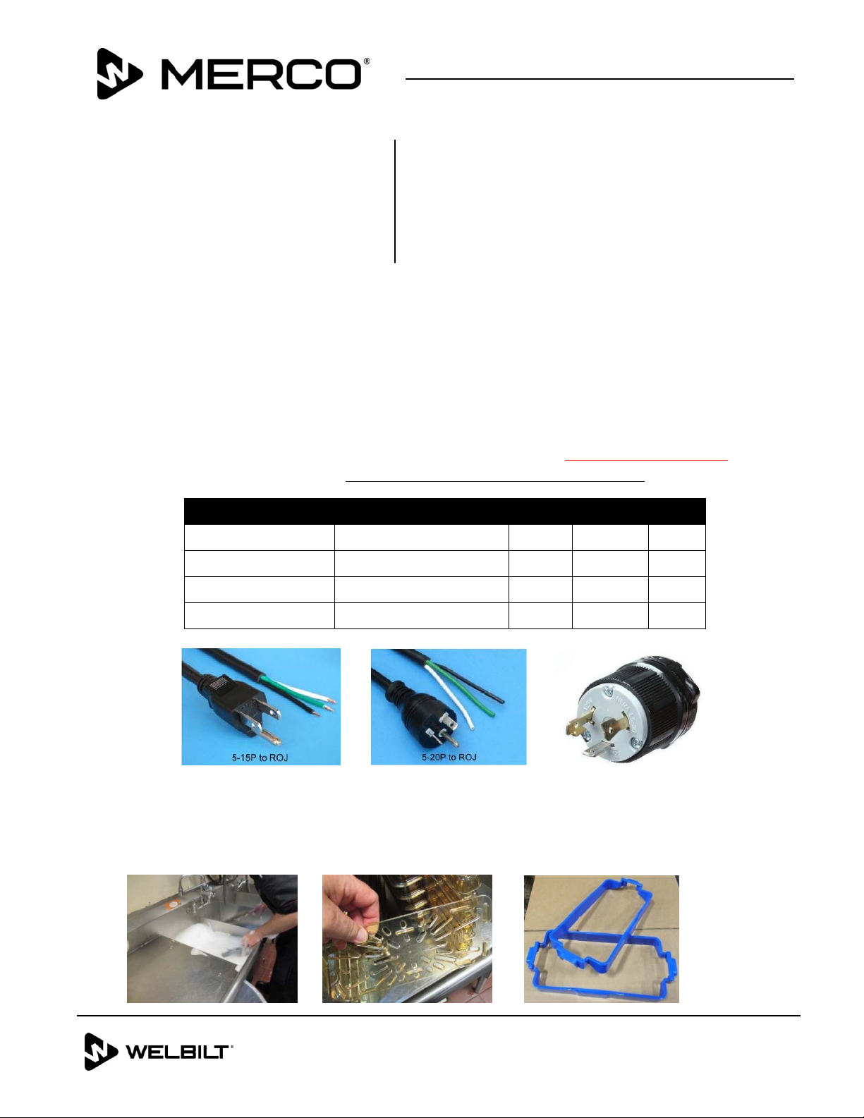
2. Ensure the proper outlets / breakers for the cabinets are installed in the store where
the cabinets are going to be located. Receptacles will be #’s 5-15R, 5-20R, & L5-30R to
match the plugs listed below. This may have to be done with a site visit.
Domestic Model Voltage, Cycle, Phase Watts Amps Plug
MHC22SNT1T 120V, 60H, 1Ph 660 5.5 5-15P
MHC24SNT2T 120V, 60H, 1Ph 1320 11.0 5-15P
MHC52SNT1T 120V, 60H, 1Ph 1920 16.0 5-20P
MHC54SNT1T 120V, 60H, 1Ph 2880 24.0 L5-30P
3. Read the Installation and Operation manual to understand proper installation, set up,
operation, cleaning, and preventive maintenance.
4. Wash all tray seal, trays, RFID collars, and trivets / false bottoms. This is done at the
store with the staffs help. See photos below and on the following page.
Subject: FAS Installation Instructions (Scope
of Work for RISE)
Models affected: MercoMax (MHC) Visual
Holding Cabinets
Instruction
Sheet
MERCO
8700 LINE AVENUE, SHREVEPORT, LA 71106
800-379-7278
WWW.MERCOPRODUCTS.COM
L5‐30P
2 of 7
Document Number: MER_IS_0009 8197479 06/2018
Subject: MHC Installation Instructions
5. Remove old cabinets and clean counters / floors as needed. Each store may have Duke
cabinets that are new enough to save and use in other locations. You may be asked to
remove, clean, and shipped to another location as an addition to the installation
pricing.
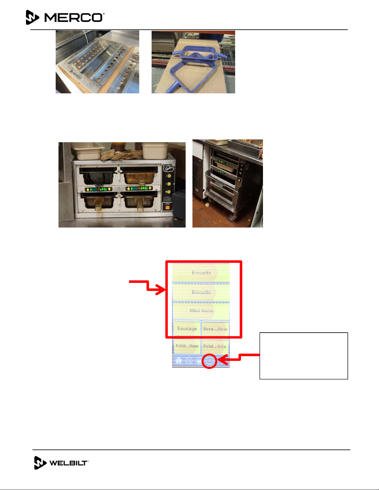
6. Plug in new Merco Cabinets and pre-heat. (approx. 15 minutes) The screen will
display a brown segment slowly covering the yellow as it gets close to set point.
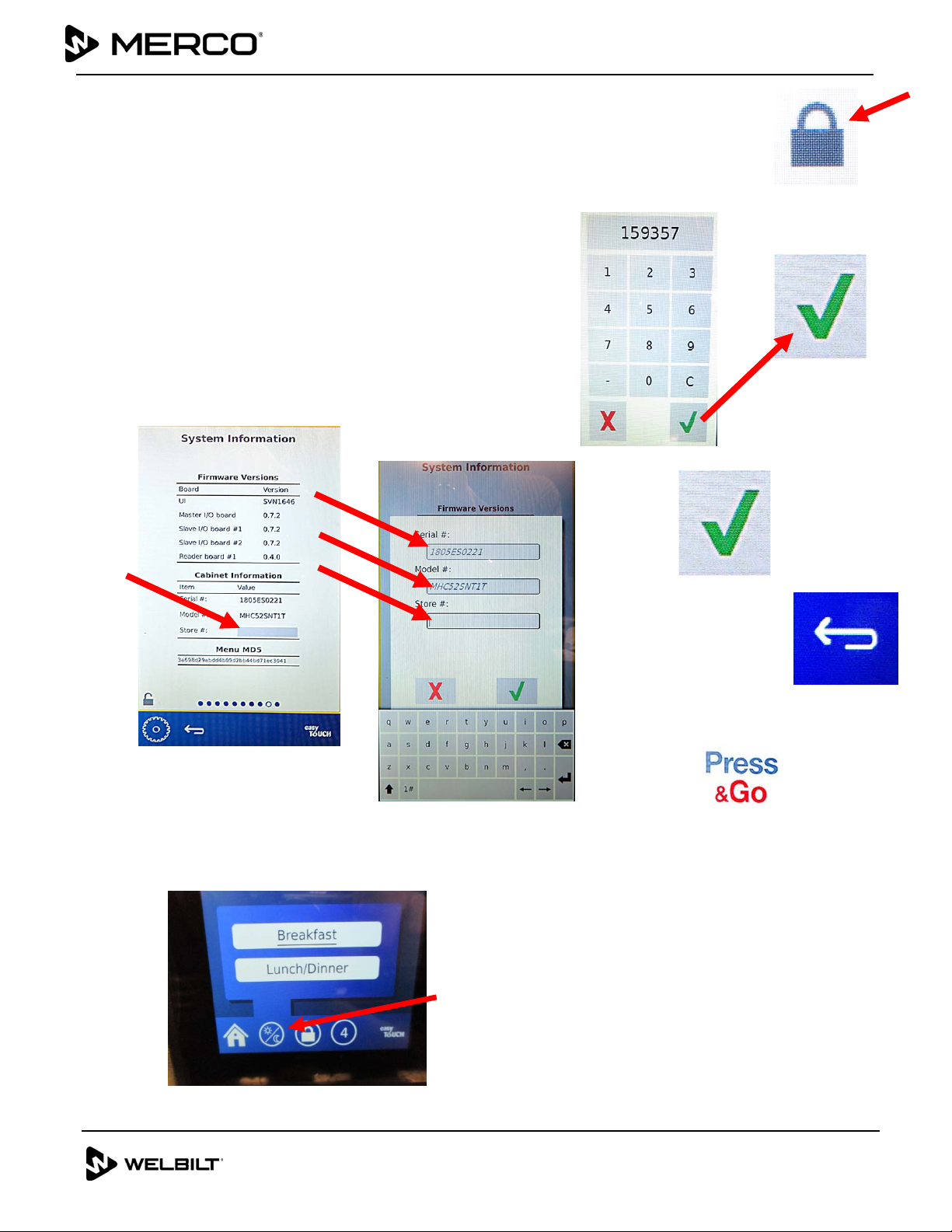
7. Verify connectivity between all cabinets by looking at the
icon on the touchscreen U.I. (See photo above).
8. Verify correct menu for the cabinet has been selected.
Pre-Heating
Screen
“Connectivity Icon”
Number should equal
the number of cabinets
in the store.
3 of 7
Document Number: MER_IS_0009 8197479 06/2018
Subject: MHC Installation Instructions
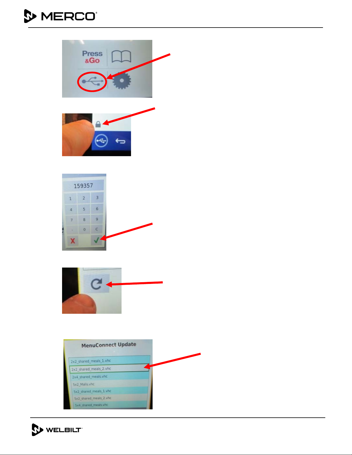
9. Press the USB Icon from the home screen.
10. Press the lock icon.
11. Enter code 159357 and press the GREEN check button.
12. Press and hold the refresh button for 3 seconds.
13. The menus are displayed. Select the menu desired. Once selected it is highlighted in
green.
4 of 7
Document Number: MER_IS_0009 8197479 06/2018
Subject:
MHC Installation Instructions
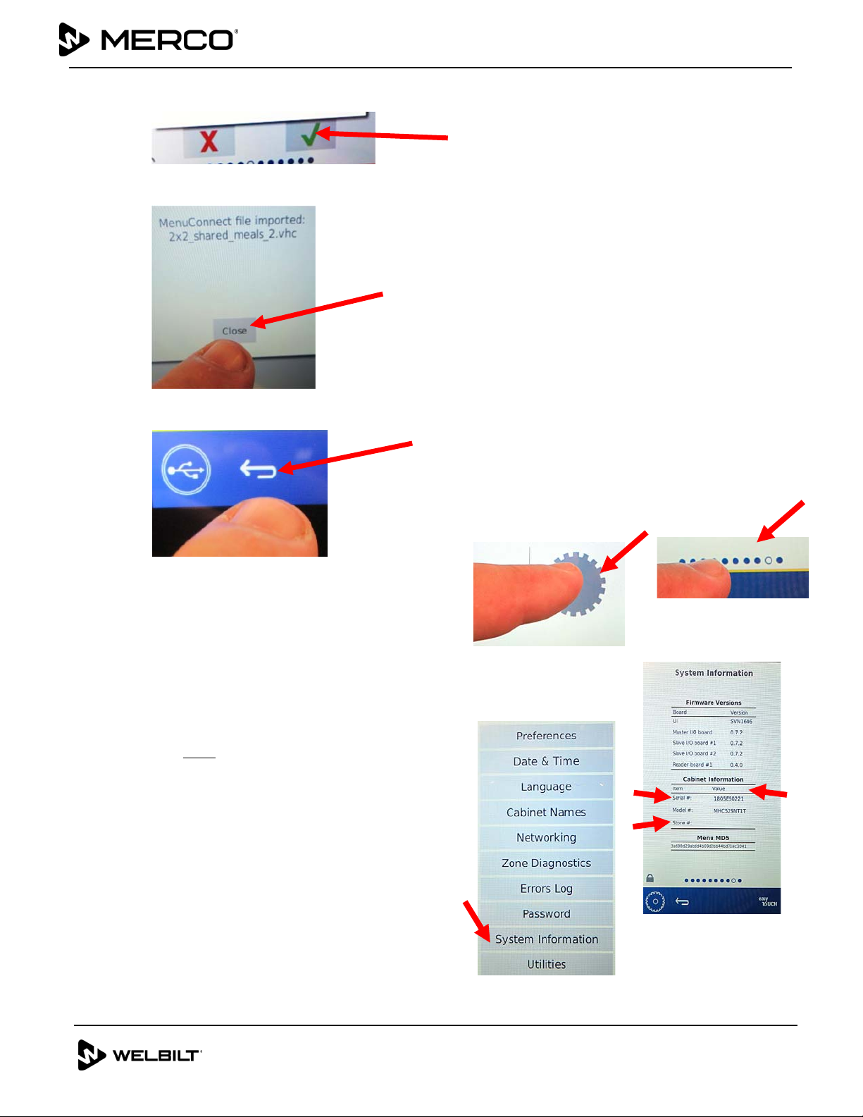
14. Press the Green check button to select the highlighted menu.
15. Press the Close button when the menu has been imported.
16. Press the “return” arrow to return to the home screen.
17. Press the tools icon (gear) from the
home screen (see Figure 10).
18. On the next screen press the row of dots at
the bottom of the screen (see Figure 11).
19. The tools options menu is displayed. Press
the System Information button (see Figure 12).
20. It is critical that the Cabinet Information
including the Serial #, the Model # and the
Store # ALL be entered into these fields (see
Figure 13). If any information is missing or
incorrect in any of these fields, the cabinets
will not communicate with other cabinets.
Figure 10
Figure 12
Figure 13
Figure 11
5 of 7
Document Number: MER_IS_0009 8197479 06/2018
Subject:
MHC Installation Instructions
21. To enter the information in the fields press the lock icon in the lower left
corner of the display (see Figure 14).
22. Enter code 159357 and press the GREEN check button (see Figures 15 and
16).
23. The fields available for edit have a shaded box (see Figure 17).
24. Press the shaded box and use the pop-up keyboard
to enter the data (see Figure 18).
25. Repeat for each field of data.
26. When finished entering the data, press the GREEN
check button (see Figure 19).
27. Press the “return” arrow to return to the home
screen (see Figure 20).
28. Press the Press & Go button to view the products
(see Figure 21).
29. Press the daypart button to select breakfast or lunch.
Figure 14
Figure 20
Figure 21
Figure 15
Figure 16
Figure 17
Figure 18
Figure 19
6 of 7
Document Number: MER_IS_0009 8197479 06/2018
Subject: MHC Installation Instructions
30. Verify correct tray seals and dividers are in the correct zones / shelves.
TRAY SPECIFICATIONS
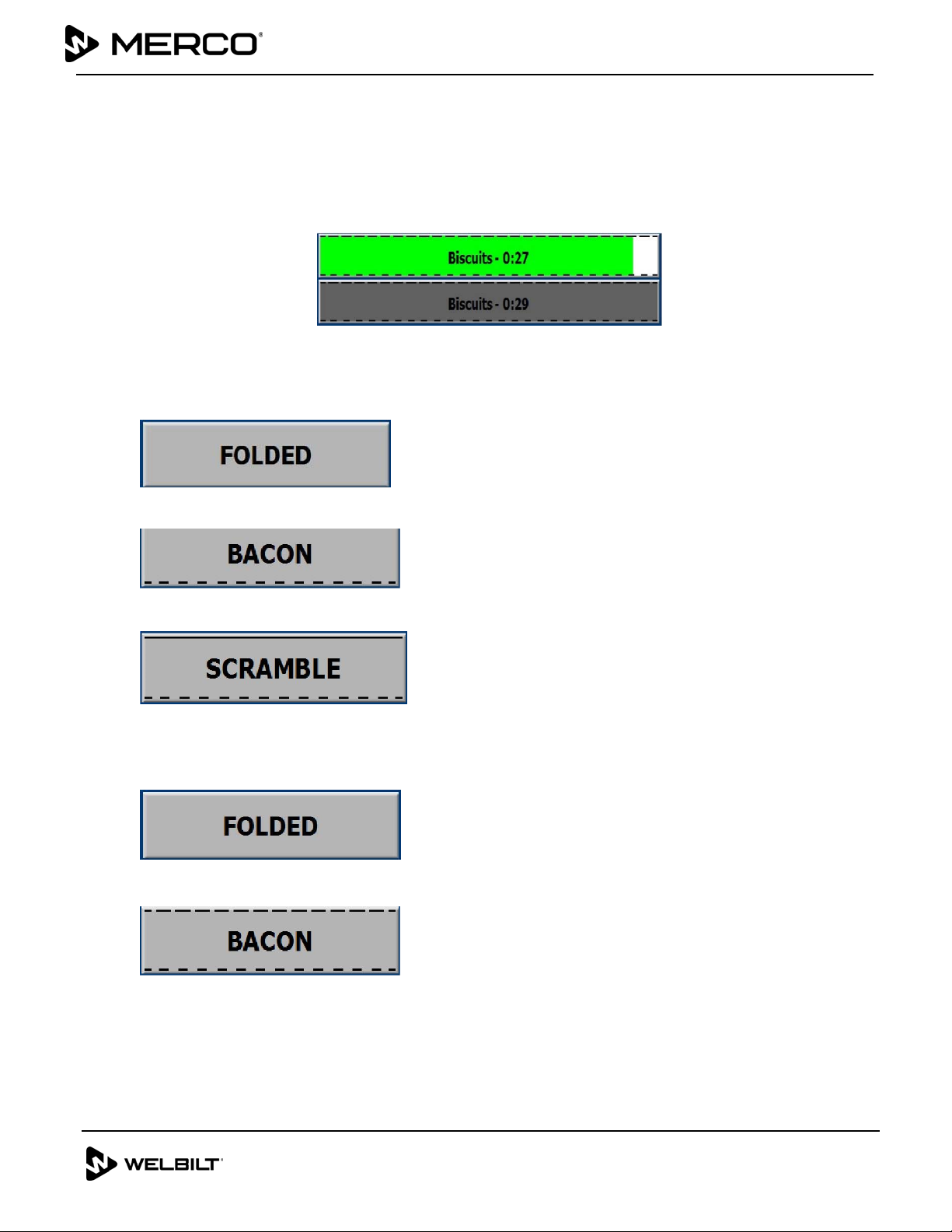
Use First For Identical Products
When two identical products are active, the one with the least time remaining will be highlighted
in green, the others in gray. There is no change is countdown or timer behavior. When the first
item is canceled or reset, the next one in order will turn green.
Use Highlighted Tray First
Lid Requirements
No line above the product name means no lid.
A dashed line above the product name represents a vented lid.
A solid line above the product represents a solid lid.
False Bottom Requirements
No line below the product name means no false bottom or a trivet is in the tray.
A dashed line below the product name means to use a false bottom.
7 of 7
Document Number: MER_IS_0009 8197479 06/2018
Subject: MHC Installation Instructions
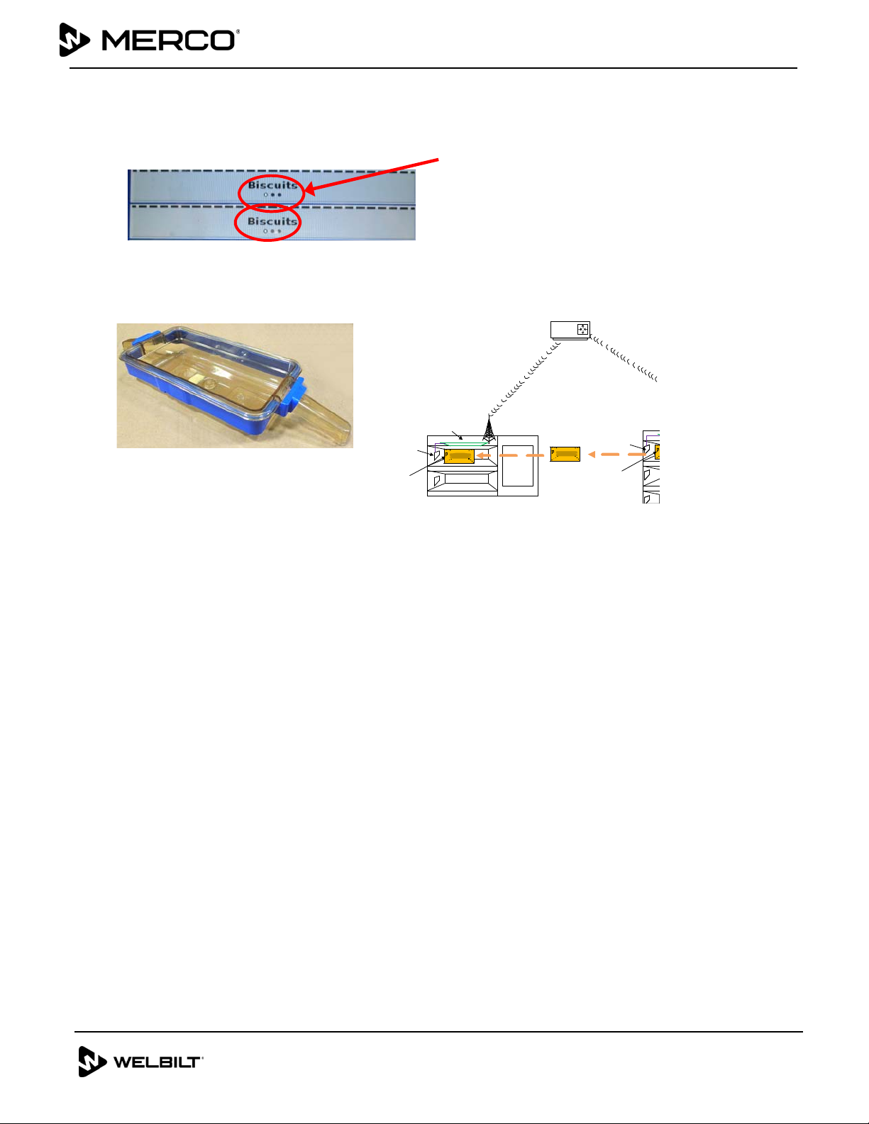
A Group in the Menu
A product in the menu is part of a group if there are dots underneath it or arrow heads on either
side of it. Select the menu item with the dots and the other items in the group will pop up and
can be selected. Swipe a product with arrow heads to choose another item from the group.
31. Install clean RFID collars on clean food bins/trays. Explain the operation of the tray
with RFID Collars and how to use.
RFIDAntenna
RF ID
Tr ansmitter
RFIDBoard
RFIDAntenna
RFID
Transmitter
Router
• The RFID identifier is built into the RFID collars above. The collars are placed on a
holding tray and initialize the unique holding time and temperature for that product
in the first holding cabinet.
• Time held is transmitted, via a wireless router, to the “Point of Use” holding cabinet
as the product is moved.
• The “Point of Use” cabinet begins displaying the remaining holding time for the
product when the RFID-equipped tray is inserted.
• The cabinets connect to the network upon installation and power up.
32. Ensure all employees that need to be are trained, on operation of the new cabinets,
are trained on the following items below:
Starting timers
Transferring trays/bins from cabinet to cabinet
Cancelling timers
Start-up in the A.M
Cleaning
P.M.
Daypart
Menu editing
This manual suits for next models
3
Table of contents


