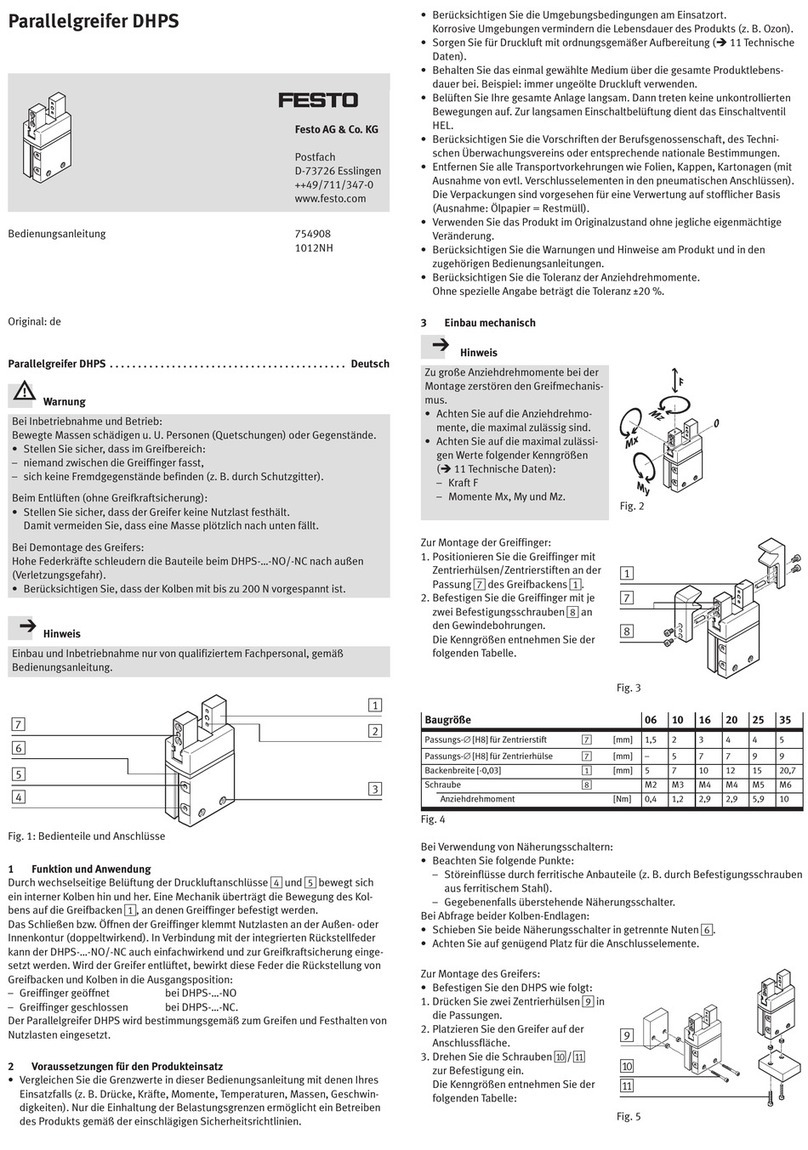
Mounting instructions (Original: de)
8037330
1407a
†‡
Adjusting kit
EADC-E12
Festo AG & Co. KG
Postfach
73726 Esslingen
Germany
+49 711 347-0
www.festo.com
1. Parts list
19344d_1
1Slot nut
2Adjusting plate
3M6x30 screw
4Square nut
5Adjusting bolt
6Washer
7Screw M8x401)
(2x)
(1x)
(2x)
(2x)
(2x)
(2x)
(2x)
19344d_2
Not included in delivery:
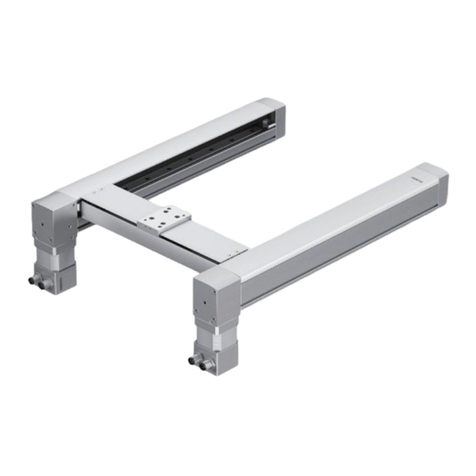
8Planar surface gantry
EXCH
(1x)
2. Intended use
Adjusting kit EADC-E12:
Attachment and alignment of the planar surface gantry EXCH. Compensation
of a difference in height of up to 5 mm.
3. Safety instructions and notes on mounting
Caution
Unexpected movement of components.
Injury due to electric shock, impact, squeezing.
Switch off power supply before mounting work.
Observe safety instructions (applicable documents).
Note
Malfunction and material damage due to incorrect mounting.
If the mounting surface is not made of steel:
Select a different screw 7suitable for the installation situation.
Thread depth ≥14 mm intended on the mounting surface for the
screws 7.
Mount properly (section 4).
Observe tightening torques.
Information
Applicable documents
Description of the planar surface gantry: EXCH (mechanical installation)
–Observe minimum number and distances of the adjusting kits.
–Align planar surface gantry.
Accessories www.festo.com/catalogue: EXCH
4. Mounting
19344d_3
Place slot nuts 1in the pro-
file slot (A).
Clamp the adjusting
plate 2to the slot nuts 1
using the screws 3.
Position the adjusting
plate 2. Observe minimum
number and distances of the
adjusting kits (Info).
Tighten screws 3.
19344d_8
Screw adjusting bolts 5
flush into the square
nuts 4.
19344d_4
Push square nuts 4includ-
ing adjusting bolts 5into
the slot (B).
19344d_5
Place washers 6under-
neath the screws 7.
Place screws 7in the mid-
dle of the oblong hole.
EADC-E12- 40 60
X [mm] 78 98
Lightly clamp the adjusting
plate 2to the mounting
surface with the screws 7.
19344d_9
Use spanner (C) with
t .5 mm.
With t ,5 mm, the possible
height compensator is smaller
by the difference (t −5).
19344d_6
Align planar surface gantry
(Info). Screw the adjust-
ing bolts 5in or out
(h = 6 … 11 mm).
Observe sufficient screw-in
depth of the screws 7 (for
steel ≥8 mm).
Tighten screws 71). Apply
counter pressure to the ad-
justing bolt 5:
–Do not twist the adjusting
bolt 5.
–Maintain alignment.
Check: alignment of the planar
surface gantry 8.
19344d_7
1)
1) Screw 7and the tightening torque are designed for mounting on steel.
A
B
9.9 Nm _20 %
C
24 Nm _20 %1)
C
C
