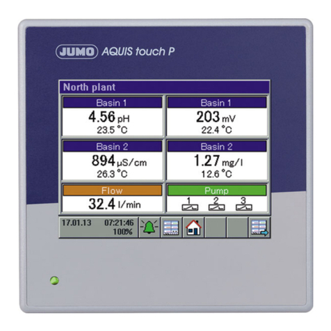
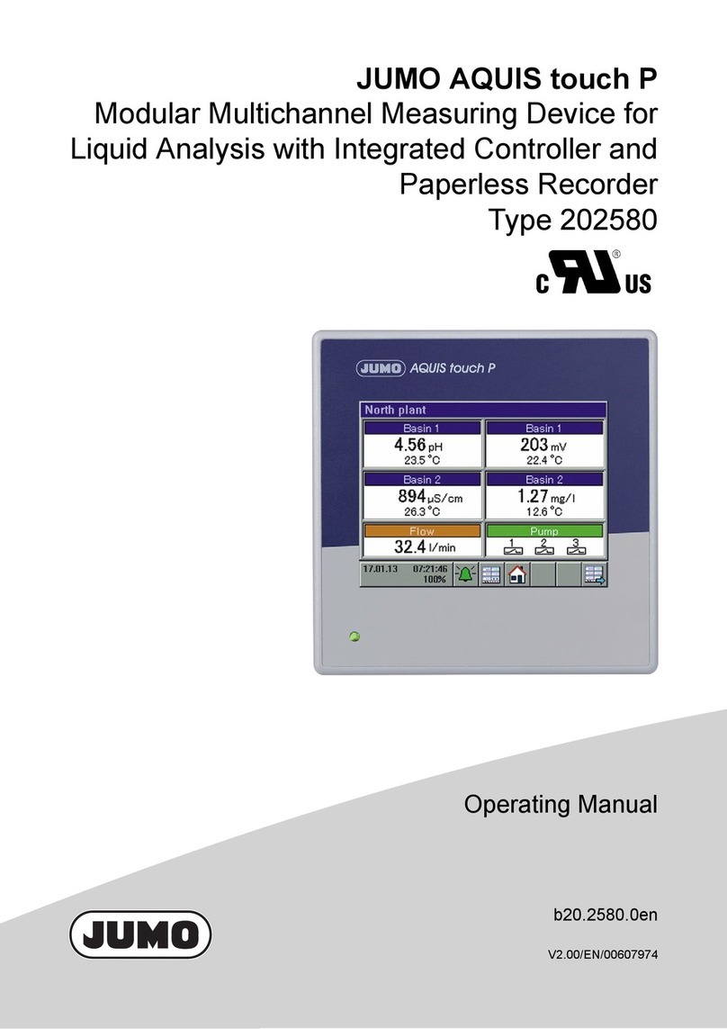
JUMO AQUIS touch S 202581 User manual

Modular Multichannel Measuring Device for
Liquid Analysis with Integrated Controller and
Paperless Recorder
Type 202581
Typ 202581
Installation Instructions
Volume 1(2)
20258100T94Z101K000
V2.00/EN/00602660
JUMO AQUIS touch S

Caution!
If the device or a sensor connected to it fails abruptly, it is likely that a dange-
rous overdosage occurres! For this case, appropriate precautionary measures
must be taken.
Notice!
Read this operating manual before putting the device into service.
Keep the operating manual at a location that is readily accessible to
all users.

Content
1 Safety information .............................................................7
1.1 Warning symbols ............................................................................... 7
1.2 Indicative symbols ............................................................................. 7
1.3 Intended use ...................................................................................... 8
1.4 Qualification of personnel .................................................................. 8
2 Acceptance of goods, storage, and transport ................9
2.1 Checking the delivery ........................................................................ 9
2.2 Important information about storage and transport ............................ 9
2.3 Returning goods ................................................................................ 9
2.3.1 Accompanying letter for repair ........................................................... 9
2.3.2 Protection against electrostatic discharge (ESD) ............................ 10
2.4 Disposal ........................................................................................... 10
3 Device Description ..........................................................11
3.1 Brief description ............................................................................... 11
3.2 Block diagram .................................................................................. 13
3.3 Device setup .................................................................................... 14
4 Identifying the device version ........................................15
4.1 Nameplate ....................................................................................... 15
4.2 Order details .................................................................................... 17
4.3 Scope of delivery ............................................................................. 20
4.4 Accessories ..................................................................................... 21
5 Mounting ..........................................................................23
5.1 Important information ....................................................................... 23
5.2 Dimensions ...................................................................................... 24
5.3 Surface mounting ............................................................................. 25
5.4 Pipe mounting .................................................................................. 28
5.5 Panel installation .............................................................................. 30
6 Electrical connection ......................................................33
6.1 Installation notes .............................................................................. 33
6.2 Installing and connecting cables ...................................................... 35

Content
6.2.1 Opening the terminal compartment on the device ........................... 35
6.2.2 Installing cables ............................................................................... 36
6.2.3 Preparing coaxial cables for pH/redox electrodes ........................... 38
6.2.4 Conductor cross-sections for base unit and power supply unit .......40
6.2.5 Conductor cross-sections for optional boards ................................. 41
6.3 Galvanic isolation ............................................................................. 42
6.4 Connection diagram ......................................................................... 43
6.4.1 Overview of connections .................................................................. 43
6.4.2 Analog inputs base unit ................................................................... 44
6.4.3 Analog inputs optional boards ......................................................... 45
6.4.4 Analog outputs ................................................................................. 54
6.4.5 Binary inputs .................................................................................... 55
6.4.6 Binary outputs, power supply unit board .......................................... 57
6.4.7 Binary outputs, optional boards ....................................................... 58
6.4.8 Mains power connection .................................................................. 59
6.4.9 Voltage supply outputs .................................................................... 59
6.4.10 Interfaces ......................................................................................... 61
7 Startup ..............................................................................67
7.1 Initial startup .................................................................................... 67
7.2 Basic setup ...................................................................................... 68
7.2.1 Date and time .................................................................................. 68
7.2.2 Basic settings ................................................................................... 69
7.3 Digital sensors ................................................................................. 70
7.3.1 Initial startup .................................................................................... 70
7.3.2 Restarting and replacing .................................................................. 74
7.4 Function test .................................................................................... 75
7.4.1 Checking the optional boards .......................................................... 75
7.4.2 Checking sensors and inputs/outputs .............................................. 75
8 Operation .........................................................................77
8.1 Operating concept ........................................................................... 77
8.1.1 Passwords and user rights .............................................................. 77
Content
8.1.2 Display and control elements ........................................................... 79
8.1.3 Menu structure ................................................................................. 80
8.1.4 Entry of text and numbers ................................................................ 86
8.2 Device menu .................................................................................... 88
8.2.1 Logon/Logoff .................................................................................... 91
8.2.2 User level ......................................................................................... 92
8.2.3 Functional level ................................................................................ 93
8.2.4 Device information ........................................................................... 95
8.2.5 Service ............................................................................................. 96
8.2.6 Calibrating the touchscreen ............................................................. 97
8.2.7 Digital sensors ................................................................................. 97
8.3 Alarm/Event list .............................................................................. 102
8.3.1 Alarm list ........................................................................................ 103
8.3.2 Event list ........................................................................................ 106
8.4 Memory Manager (USB flash drive) .............................................. 108
9 Retrofitting optional boards .........................................111
9.1 Installing optional boards ............................................................... 111
9.2 Energy balance test ....................................................................... 114
9.2.1 Monitoring the internal temperature ............................................... 115
9.2.2 Installing the JUMO PC setup program ......................................... 115
9.2.3 Performing the energy balance test ............................................... 118
9.3 Ci base calibration ......................................................................... 121

Content

7
1 Safety information
1.1 Warning symbols
1.2 Indicative symbols
DANGER!
This symbol indicates that the risk of personal injury from electrocution exists
if the appropriate precautionary measures are not taken.
WARNING!
In conjunction with the signal word "Warning", this symbol indicates that the
risk of personal injury or death exists if the appropriate precautionary measures
are not taken.
CAUTION!
In conjunction with the signal word "Caution", this symbol indicates that the risk
of equipment damage or data loss exists if the appropriate precautionary mea-
sures are not taken.
CAUTION!
This symbol indicates that components of the device can be destroyed by elec-
trostatic discharge (ESD = Electro Static Discharge) if the appropriate precau-
tionary measures are not taken. When returning modules, assemblies, or
components from the device, use only the ESD packaging provided.
READ THE DOCUMENTATION!
This symbol, which is attached to the device, indicates that the associated doc-
umentation for the device must be observed. This is necessary in order to rec-
ognize the nature of the potential danger and take the necessary measures to
avoid it.
HOT SURFACE!
This symbol is used if burns can result from touching a hot surface.
NOTE!
This symbol refers to important information about the product, its handling,
or additional use.
REFERENCE!
This symbol refers to additional information in other sections, chapters, or
other instructions.
?

1 Safety information
8
1.3 Intended use
The JUMO AQUIS touch S is designed for measurement, control, and automa-
tion tasks in industrial environments as specified in the technical data. Use for
any other purpose is considered contrary to the intended use.
v Chapter 20 "Technical data", Page 107
The device has been manufactured in compliance with applicable standards and
guidelines as well as applicable safety regulations. Improper use can result in
personal injury or property damage.
To avoid risks, the device may be used only as follows:
• For the intended use
• when in good order and condition
• when taking into account the technical documentation provided
Risks resulting from the application may arise, e.g. as the result of missing safe-
ty provisions or wrong settings, even when the device is used properly and as
intended.
1.4 Qualification of personnel
This document contains the information required to ensure use of the device as
intended. It is meant for technically qualified individuals who have been specially
trained and have the appropriate know-how in the field of automation technology
(measurement and control instrumentation).
Understanding and technically correct observance of the safety instructions and
warnings contained in the supplied documentation are prerequisites for safe
mounting, installation, and commissioning as well as safety during operation.
Only qualified individuals have the required technical knowledge to interpret and
put into practice the safety instructions and warnings used in this documentation
in any given situation.
DISPOSAL!
At the end of its service life, the device and any batteries present do not belong
in the trash! Please dispose of them as required by regulations and in an envi-
ronmentally sound manner.

9
2 Acceptance of goods, storage, and transport
2.1 Checking the delivery
• ensure that the packaging and its contents are undamaged
• check the delivery for completeness against the packing slip and order con-
firmation
• inform the supplier immediately if there is any damage
• retain damaged parts until the situation has been clarified with the supplier
2.2 Important information about storage and transport
• store the device in a dry, clean environment
• observe the permissible ambient conditions,
v Chapter 20 "Technical data", Page 107
• protect the device from shock during transport
• the original packaging offers optimal protection for storage and transport
2.3 Returning goods
• if repairs are needed, return the device in clean condition and in its entirety
• use the original packaging when returning the device
2.3.1 Accompanying letter for repair
Please include the completed accompanying letter for repair when returning
goods. Do not forget to state the following:
• Description of the application
• Description of the error that has occurred
The accompanying letter for repair is linked to www.jumo.de on the Internet un-
der the heading Service & Support as follows:
Product Service rRepair Service rReturning a device

2 Acceptance of goods, storage, and transport
10
2.3.2 Protection against electrostatic discharge (ESD)
To prevent damage from ESD, electronic assemblies, or components with a
high internal resistance must be handled, packaged, and stored in an environ-
ment that protects against ESD. Measures that protect against electrostatic dis-
charge and electric fields are described in DIN EN 61340-5-1 and DIN EN
61340-5-2 "Electrostatics – Part 5-2 – Protection of electronic devices from elec-
trostatic phenomena".
When sending back electronic assemblies or components, please note the fol-
lowing:
• Pack sensitive components only in an environment providing protection
against ESD. Such workplaces conduct existing electrostatic charges to
ground in a controlled manner and prevent electrostatic charge buildup due
to friction.
• Use only packaging intended specifically for ESD-sensitive assemblies/com-
ponents. These must be made from conductive plastics.
No liability is assumed for damage caused by electrostatic discharge (ESD).
2.4 Disposal
Disposing of the packaging material
All packaging material is recyclable.
CAUTION!
Electrostatic charges occur in non-ESD-protected environments.
Electrostatic discharge can damage assemblies or components.
For transport purposes, use only the ESD packaging provided.
DISPOSAL!
At the end of its service life, the device and any replaced parts do not belong
in the trash. These items are made from materials that can be reclaimed
through "recycling".
Dispose of the device and the packaging material as required by regulations
and in an environmentally sound manner!
The country-specific laws and regulations for handling and disposing of waste
must be observed!

11
3 Device Description
3.1 Brief description
Trade fairs
The JUMO AQUIS touch S provides a central platform for the display and pro-
cessing of pH value, Redox voltage, electrolytic conductivity, resistance of high-
purity water and temperature as well as quantities of disinfecting agents such as
free chlorine, total chlorine, chlorine dioxide, ozone, hydrogen peroxide and per-
acetic acid or even flow rates. Pulse frequency inputs (counters) are available
for flow rate measurement. Universal inputs can be used to measure almost any
analog measurands using standard signals (4 to 20 mA or 0 to 10 V). The unit
can measure and manage up to 25 parameters simultaneously.
Controlling
In addition to numerous simple alarm, limit value or timed switching functions,
up to 4 higher-level, simultaneous control loops can be defined in the JUMO
AQUIS touch S. These make use of the time-tested JUMO control algorithms for
P, PI, PD, and PID control.
Display
A 5.5" touch-sensitive color screen is responsible for display of all parameters
as well as operation and device settings. The plain text operating philosophy
simplifies operation of the device by the user. German, English and, on request,
French are included in the device at the factory as selectable user interface lan-
guages.
v Chapter 4.2 "Order details", Page 17
Using the PC setup program, the language library of the unit can be expanded
to as many as 15 languages. It's also possible to display languages that use Chi-
nese and Cyrillic characters. The device is thus predestined for use around the
world.
Recording
A paperless recorder is incorporated to record data. Up to 8 analog quantities
and 6 binary signals are registered and displayed on the screen in a time-depen-
dent curve. Storage is tamperproof and facilitates compliance with governmen-
tal recording obligations. The data can be read out using the JUMO PCC
software or to a USB flash drive for evaluation by the JUMO PCA 3000 PC eval-
uation software.

3 Device Description
12
Application examples
The modular setup and open structure of the device permits a host of potential
applications:
• Municipal and industrial water treatment in wastewater treatment plants
• Process systems
• Drinking and bathing water monitoring
• Pharmaceutical water
• Food and beverage production (CIP/SIP plants)
• Gas scrubbers / air washers
• Cooling tower control
• Ion exchangers
• RO-units (reverse osmosis)
• Power stations and energy plants
• Fish breeding
• Desalination of seawater
NOTE!
The device is not suitable for use in a potentially
explosive atmosphere.

13
3 Device Description
3.2 Block diagram
Voltage supply
according - order details
AC 110 to 240 V, 48 to 63 Hz or
AC/DC 20 to 30 V, 48 to 63 Hz
parallel tap from PWR IN,
e.g. for supplying pumps
Voltage supply outputs:
DC ±5 V for ISFET pH-sensors
and DC 24 V (see
order details) for
transmitters, sensors etc.
Relay switching output with
changeover contact
Serial interface for
Modbus and digiLine
Optional board:
RS422/485 (Modbus and digiLine)
PROFIBUS-DP
Relay switching outputs with
normally open contact
Standard signals
0 to 10 V or 0(4) to 20 mA
Power supply unit and base unit
with series connections
Expansion slots
for AddOn with
Optional boards
PWR IN
OUT 1 binary output
DC ±5 V
DC 24 V
2× PWR OUT
OUT 3 binary output
OUT 4 analog output
OUT 5 analog output
OUT 2 binary output
USB device interface
COM 1 RS422/485
OUT 8/9
Analog/binary output
IN 11 analog input
IN 12 analog input
OUT 6/7
Analog/binary output
Ethernet
COM 2
COM 2
IN 11
IN 12
OUT 16/17
OUT 18/19
OUT 14/15
OUT 12/13
OUT 10/11
LAN
IN 7 Option analysis 1
IN 8 Option analysis 2
IN 9 Option analysis 3
IN 10 Option analysis 4
OUT 10/11
Analog/binary output
OUT 12/13
Analog/binary output
OUT 14/15
Analog/binary output
OUT 16/17
Analog/binary output
OUT 18/19
Analog/binary output
for web server, e-mail, setup
program, Modbus TCP/IP and
JUMO PCC/PCA3000
Optional boards for
Analog outputs:
Optional boards for
binary outputs:
only OUT 14/15
Optional board for
voltage supply
outputs
Standard signals 0 to 10 V/
0(4) to 20 mA
1-way relay changeover contact/
2-way relay normally open contact/
1-way solid state relay triac/
2-way solid state relay
PhotoMOS®/
1-way logic output 0/22 V/
2-way logic output 0/12 V
:
DC ±5 V for ISFET pH-sensors
DC 24 V for
transmitters, sensors etc.
Input for standard signal
(current signal) 0(4) to 20 mA
via USB flash drive firmware,
extract measurement-data memory,
save service data,
save/load configuration
Pt100, Pt1000,
RTD temperature probe with
customer-specific characteristic line,
IN 5 additionally: update resistance
transmitter and NTC
Switching signals
Pulse frequency signals
for e.g. manual
mode, timer start/stop etc.
IN 2 and IN 3 additionally:
for
Pulse generator, e.g. impeller
sensors for flow measurement
IN 1 binary input 1
IN 6 universal input
IN 2 binary input 2
IN 3 binary input 3
IN 4 temperature input 1
IN 5 temperature input 2
USB host interface
(optional)
Optional board
Universal inputs:
0(4) to 20 mA, 0 to 10 V, Pt100,
Pt1000, RTD temperature probe
with customer-specific characteristic
line, Resistance transmitter
IN 13/14/15
Binary inputs
IN 16/17/18
Binary inputs
Optional board
3-way binary input:
for up - 3 switching signals
Optional boards for
analysis inputs
(in any combination):
pH-value/redox potential/NH
electrolytic conductivity
(conductive)
electrolytic conductivity
(inductive)
3
for pH sensors (conventional and
ISFET), redox-, or NH sensors/
for
Conductivity sensors
in 2-/4 conductor technology/
for inductive
conductivity sensors from JUMO
3
IN 7
IN 8
IN 9
IN 10
IN
13/14/15
IN
16/17/18
OUT 8/9
OUT 6/7
for setup program and
extract measurement data via
JUMO PCC/PCA3000

3 Device Description
14
3.3 Device setup
(1) TFT-touchscreen
(2) Case (terminal compartment cover opened)
(3) Connection terminals, power supply unit
(4) Connection terminals, base unit
(5) Expansion slots
(6) USB interfaces (USB device interface and connection for optional USB
host socket)
(7) USB host socket, IP67 (also available, see Extra Code 269 Chapter 4.2
"Order details", Page 17)
(8) Cable fittings
(1)
(2)
(3) (4)
(5)
(7)
(8)
(6)

15
4 Identifying the device version
4.1 Nameplate
The nameplate on the device enclosure identifies the device version. It is locat-
ed on the outside of the enclosure on the right.
Example of a nameplate
It is helpful to become familiar with the technical features of the device prior to
startup. Compare the type code on the nameplate with the order details.
(1) Data matrix code (for service purposes)
(2) Information symbol (Read documentation!
⇨Chapter 1.1 "Warning symbols", page 7
(3) Part number
(4) Serial number
(5) Approval mark
(6) Voltage supply
(7) MAC address of the Ethernet interface (saved in the device and thus ap-
plicable to retrofitted or replacement Ethernet optional boards as well)
(8) Type code
(1)
(2)
(3)(4)
(6)
(8)
(7)
(5)

4 Identifying the device version
16
⇨ "Order details", page 17
In the event of technical questions, please have the information from the name-
plate available for the member of our support team.

17
4 Identifying the device version
4.2 Order details
NOTE!
In addition to the standard languages of German, English, and French, 13 ad-
ditional languages (e.g. Russian, Chinese, Italian etc.) are available. Please
use the contact information on the back of this manual to contact JUMO in this
regard.
Slot
(1) Basic type
202581 JUMO AQUIS touch S
(2) Version
8 Standard with default settings
9 Customer-specific configuration (specification in plain text)
(3) National language
01 German
02 English
03 French
(4) Analysis input 1 IN 7
0 Not used
1 pH/Redox/NH3
2 CR resistive conductivity measurement (2 and 4-pole)
3 Ci inductive conductivity measurement
(5) Analysis input 2 IN 8
0 Not used
1 pH/Redox/NH3
2 CR resistive conductivity measurement (2 and 4-pole)
3 Ci inductive conductivity measurement
(6) Analysis input 3 IN 9
0 Not used
1 pH/Redox/NH3
2 CR resistive conductivity measurement (2 and 4-pole)
3 Ci inductive conductivity measurement
(7) Analysis input 4 IN 10
0 Not used
1 pH/Redox/NH3
2 CR resistive conductivity measurement (2 and 4-pole)
3 Ci inductive conductivity measurement

4 Identifying the device version
18
(8) Input/output 1 IN 11, OUT 6/7
00 Not used
10 Universal input
11 Relay (changeover contact)
12 2× relays (normally open contact)
13 Solid state relay triac 230 V, 1 A
14 Logic output 0/22 V
15 2× logic outputs 0/12 V
16 analog output
17 2× solid state relay PhotoMOS®a
(9) Input/output 2 IN 12, OUT 8/9
00 Not used
10 Universal input
11 Relay (changeover contact)
12 2× relays (normally open contact)
13 Solid state relay triac 230 V, 1 A
14 Logic output 0/22 V
15 2× logic outputs 0/12 V
16 analog output
17 2× PhotoMOS®a solid-state relay
(10) Input/output 3 IN 13/14/15,
OUT 10/11
00 Not used
11 Relay (changeover contact)
12 2× relays (normally open contact)
13 Solid state relay triac 230 V, 1 A
14 Logic output 0/22 V
15 2× logic outputs 0/12 V
16 analog output
17 2× PhotoMOS®a solid-state relay
18 3× digital inputs
(11) Input/output 4 IN 16/17/18,
OUT 12/13
00 Not used
11 Relay (changeover contact)
12 2× relays (normally open contact)
13 Solid state relay triac 230 V, 1 A
14 Logic output 0/22 V
15 2× logic outputs 0/12 V
16 analog output
17 2× PhotoMOS®a solid-state relay
18 3× digital inputs

19
4 Identifying the device version
(12) Output 5 OUT 14/15
00 Not used
11 Relay (changeover contact)
12 2× relays (normally open contact)
13 Solid state relay triac 230 V, 1 A
14 Logic output 0/22 V
15 2× logic outputs 0/12 V
16 analog output
17 2× PhotoMOS®a solid-state relay
19 Supply voltage output ±5 V DC, 24 V
(13) Output 6 OUT 16/17
00 Not used
11 Relay (changeover contact)
12 2× relays (normally open contact)
13 Solid state relay triac 230 V, 1 A
14 Logic output 0/22 V
15 2× logic outputs 0/12 V
16 analog output
17 2× PhotoMOS®a solid-state relay
(14) Output 7 OUT 18/19
00 Not used
11 Relay (changeover contact)
12 2× relays (normally open contact)
13 Solid state relay triac 230 V, 1 A
14 Logic output 0/22 V
15 2× logic outputs 0/12 V
16 analog output
17 2× PhotoMOS®a solid-state relay
(15) Voltage supply
23 AC 110 to 240 V +10/-15 %; 48 to 63 Hz
25 AC/DC 20 to 30 V; 48 to 63 Hz
(16) Interface Com2 COM 2
00 Not used
54 RS422/485 Modbus RTU
64 PROFIBUS-DP
(17) Interface Com3 LAN
00 Not used
08 Ethernet
(18) Voltage output
1DC12V
2DC24V

4 Identifying the device version
20
4.3 Scope of delivery
Content of the JUMO AQUIS touch S accessories kit
(19) Extra code
000 None
213 Recording function
214 Math and logic module
269 USB host socket (IP67)
962 JUMO digiLine protocol activated
aPhotoMOS® is a registered trademark of Panasonic.
(1) (2) (3) (4) (5) (6) (7) (8) (9) (10) (11)
Order code: /----------
Order example: 202581 / 8 - 01 - 1 - 2 - 0 - 0 - 10 - 10 - 13 - 13 -
(12) (13) (14) (15) (16) (17) (18) (19)
------/,...
a
11 - 11 - 11 - 23 - 64 - 00 - 1 / 213 , 214
aList all desired extra codes separated by commas.
JUMO AQUIS touch S according to order details
Mini-DVD with JUMO PC setup program as demo version, Adobe Acrobat Reader, operating manual
and data sheet in PDF format, GSD generator and JUMO PCC / PCA 3000 as demo version
JUMO AQUIS touch S accessories kit, part no. 00597460
Mounting plate for surface mounting, part no. 00597799
Terminal diagram sticker
Installation instructions in 2 volumes B 202581.4
6× M12 × 1.5 hexagon nut
6× gasket 10.2 × 14.5 × 1 for M12 cable fitting
6× M12 × 1.5 cable fitting
6× plug for M12 cable fitting
3× M16 × 1.5 hexagon nut
3× gasket 14.2 × 19.5 × 1 for M16 cable fitting
3× M16 × 1.5 cable fitting
3× plug for M16 cable fitting
26× cable tie 2.5 × 98 PA
3× self-tapping screw 60 × 16 TORX PLUS®a 30IP (for panel mounting kit)
1× snap ferrite to suppress interference from the power supply cable to the device
aTORX PLUS® is a registered trademark of Acument Intellectual Properties, LLC. USA.
Table of contents
Other JUMO Measuring Instrument manuals

JUMO
JUMO 202710 User manual

JUMO
JUMO flowTRANS MAG S01 Instruction manual

JUMO
JUMO LOGOSCREEN User manual

JUMO
JUMO PINOS L02 User manual

JUMO
JUMO DI ECO User manual

JUMO
JUMO Dtrans T100 User manual

JUMO
JUMO meroTRON 104 User manual

JUMO
JUMO MAERA S29 SW User manual

JUMO
JUMO NESOS Series User manual

JUMO
JUMO 202710 User manual

JUMO
JUMO 902020/10 User manual

JUMO
JUMO LOGOSCREEN 700 Reference guide

JUMO
JUMO flowTRANS MAG H20 User manual

JUMO
JUMO TDA-3000 User manual

JUMO
JUMO dTRANS p35 Reference guide

JUMO
JUMO Wtrans E01 User manual

JUMO
JUMO 202710/20 User manual

JUMO
JUMO meroVIEW 104 Reference guide

JUMO
JUMO miroVIEW Reference guide

JUMO
JUMO flowTRANS MAG S Series User guide