Merkava FatFold500 User manual

FatFold500
User Manual

FatFold500 Quick Start Guide:
1. Carefully remove contents of box out ofthe packaging.
You will find:
. 1x FatFoldsoo eBike
. 1x110VCharger
. 1x mud guard (optional)
. 1 x Rear rack (optional)
. 2xKeys
2. Fold open the eBike and close the quick release latch on theframe.
3. lnstall Front wheel and tighten quick release latch.
4. Place handle bar in place and tighten allen screws
5. Place seat to desired height and tighten quick release latch.
6. lnflate tires to about 15 20PS1
7. Place your FatFold500 on a raised surfaceforeasy inspection while securing one ofthe
wheels so it stays in place then proceed to visr.rallY check the FatFold500 components and
ensure that all screws and bolts are tightened and that tires are correctly inflated. Check and
adjust break lever to your preference and check that the derailleur functions properly. This
is usually already done once at the factory and once before shipping but as a precautionary
measure we recommend you do this as well before ridinS as some components may shift
during transport.
8. Charge your FatFold50o in a clean environment at ambient temperature until light on the
chargerturns from red to green. You can charge the battery while still inside the frame of
the eBike or you may remove the battery and charge it independently. To remove the
battery pack open the quick release latch on the frame and fold the eBike, insertthe key
underthe frame, push and turn it clockwise untilthe lock pin goes inside the battery.
Remove the kev and slowlv pull out battery pack. Repeat process in the inverse order to re
insert the battery pack into frame.
9. Once you've familiadzed yourselfwith the digitaldisplay you willbe ready to ride- Please
ride carefullyl (see attached instruction for 5-900 display)
IMPORTANT NOTE: To AVorD oaMAGTNG youR BATTERY pAc( wE srRoNGLy REcoMMENo
USER SHUTS DOWN ANO RECHARGETHE FatFoIdsOO ONCE BATTERY LEVEL REACHES 1O%. YOU WILL
CNTER THIS CRITICAI. LEVEI. SHORTI.Y AFIER YOUR DISPLAY SHOWS l BAR OR REACHES 4OV IN THE
VOLTAGE METER.

Maintaining your FatFolds(}o battery Pack:
Before shipping, we conduct spot checks on ourtransporters to validate overall quality and condition of
electrical components including motor and battery pack. These checked units have their battery tested
and fully charged before shipping.
The lithium ion technology is intended to last for several years while being charged and discharged many
times- However, the battery's life span willdepend on your care ofthe battery.
Battery life will depend on your maintenance and care ofthe battery. FatFoldS00 uses advanced
Lithium-lon batteries made with high capacity Panasonic cells and they should be charged at least once
a month (when not in use) to ensure the longevity of your battery. Make sure to onlY use our supplied
48V charger on your48v battery.
Allow your batteryto rest for 10 minutes after charging before riding and for 10 min after riding before
charging. Unplu8 your battery charger after the li8ht turns green indicating your battery is fully charged.
Always unpluB the charger from the walloutlet before plugein1 ot unplugging the other end into your
FatFold500.
Typical charging time afterthe battery has reached the 10% critical low level is between 4 to 5 hours
usinB the 3Ah charger provided.
Coutior: Do not expose your battery to extremely low or high temperatures to avoid potential damage
to Your battery,>>
IMPORTANT NOTE: TO AVOID DAMAGING YOUR BATTERY PACK WE STRONGLY RCCOMMEND
USER SHUTS DOWN AND RECHARGE THE FAIFOId5OO ONCE BATTERY I"EVEI. REACHES 1O%. YOU WII.L
ENTERTHIS CRITICAL TEVEL SHORTLY AFTER YOUR DISPLAY SHOWS l BAR OR REACHES 4OV IN THE
VOLTAGE METER.

Warranty information:
tlcrkala slandr hrhind its products. All our trnnsportcrs bencfit from a 2 Jcar limitcd
\\ t riino.
The COMPANY rvarra.rts that the frame will be Iiee from defecrs in the materials ard
workmanship for a period of2 years.
The COMPANY wanants that the motor and battery pack will be free fiom defects in the
matedals and workmanship for a period of 1 year*.
-l'he COMPANY waranls that the electrical componeots including the controller and
charger will be free fiom defects in the matedals and workmanship for a period of6 months.
Before shipping, we conduct spot checks on our tr.utsponeE b validate overall quality and
condition ofelectrical components including motor and battery pack. These checked uits have
lheir baftery lested ,rd firlly charged before shipping.
The lithium ion technology we use is intended to last for several years while being charged a.nd
discharged many times. However, the battery's life span will depend on your care ofthe baftery.
Ifthe PRODUCT proves defective AND a claim is filled duing the waranty period. the
COMPANY at its optior! will:
Repair the PRODUCT by meaN oftelephone support, email support, or by providing the
necessary parts at no charge.
Warranty claims must be filed with Merkava by email: info@merkava-ca
tvarranty on baftery will be limited to 6 months if it is determioed thal our guidelines for proper
baftery care have llot been followed.
The following are nol covered by thc warraDty:
. Wear and tear on frame, gdp tape, levers, tubes, tires, brake discs, brake pads, cables,
seats, plastic fairings and any other component which wea$ out naturally du ng usage.
. Minor scratches and stress marks that may occur during shipping and handling.
. Water damage caused by exposing sensitive electrical parts to water such as washing
transporter with hose or pressure washer.
. Accidents, misuse, abusg human e.rors or lack ofmaintenance.
. Acts-of-god such as fire, flood, ea hquake, lieezing, etc

Warranty information continued:
The following will void the warraniy:
. The modificalion ofyour transporter or use outside those specified on this site.
. The sgrial number ofthe product has been ahered or removed-
. The product has been dismantled and repaired/rcassembled with allerma*et pafts.
. Overloading yotrl ffansporter.
. Storing your hansporter outdoors.
IMPoRTANT NOTE: To AVorD DAMAGTNG youR BATTERY pAc( wE STRoNGLY REcoMMEND
USER SHUTS DOWN AND RECHARGE THE FAIFOIdSOO ONCE BATT€RY LEVEL REACHES 1O%. YOU WILL
ENTER THIS CRITICAL TEVEI SHORTLY AFTER YOUR DISPTAY SHOWS 1 BAR OR REACHES 4OV IN THE
VOI-IAGE METER.

Safe Operation:
Always wear a Helmei
. AlwaYs Start in the slow PedalAssist mode
. Grip both hand grips
. Check brake level for positive braking action
. Turn lgnition to on by insertint the key at the bottom of the frame and turning
counter clock wise
. Press the power button on the display
. Start pedaling, motor will kick in within a second or two
. Once your comfortable riding the eBike on Pedal tusist Mode you can start using the
throttle instead of Pedaling.
. You should only use oNE riding mode at a time. lf using throttle do not pedal lfpedaling
with pedal assist mode do not use throttle.
. Please note, throttle only riding will lower the max range on a charge considerably
. ALWAYS follow your local laws regarding eBikes and be respectful of other riders on the
road and on trails.
Helmet
Alwavs wear an ASTM and CPSC certified helmet when riding. Make sure that chin strap is
attached before your ride and follow the helmet manufactures instructions for proper user and
fit.
Footwear
Make sure to always wear shoes that have good traction on the pedals and will stay on your
feet.
Brakes
Squeeze the hand brake levers to ensure there is positive braking action before starting your
ride.
IMPORTANT NOTE: To AVoID DAMAGING YouR BATTERY PAGK wE STRoNGLY RECoMMEND
USER SHUTS DOWN AND RECHARGE THE TAIFOIdSOO ONCE BATTERY LEVEL REACHES 1O%. YOU WILL
ENTERTHIS CRIIICAL LEVEL SHORTLY ATTER YOUR DISPLAY SHOWS l BAR OR REACHES 4OV IN THE
VOLTAGE METER.

1. Material&Dimension
1) Material
Caser and Cover and Press button: ABS,
LCD window: PMMA
2) Outside and mounting dimensions{mm)
cfl q
Srrew 4'16 s.ew 4'25
'11-
60.?5
16 98 tt
3) Press button outside and mounting dimensions(mm)
s<ew 2.8 S<ew 4'15
t
I
-2
-It,06-
"b
- .i/ t-l
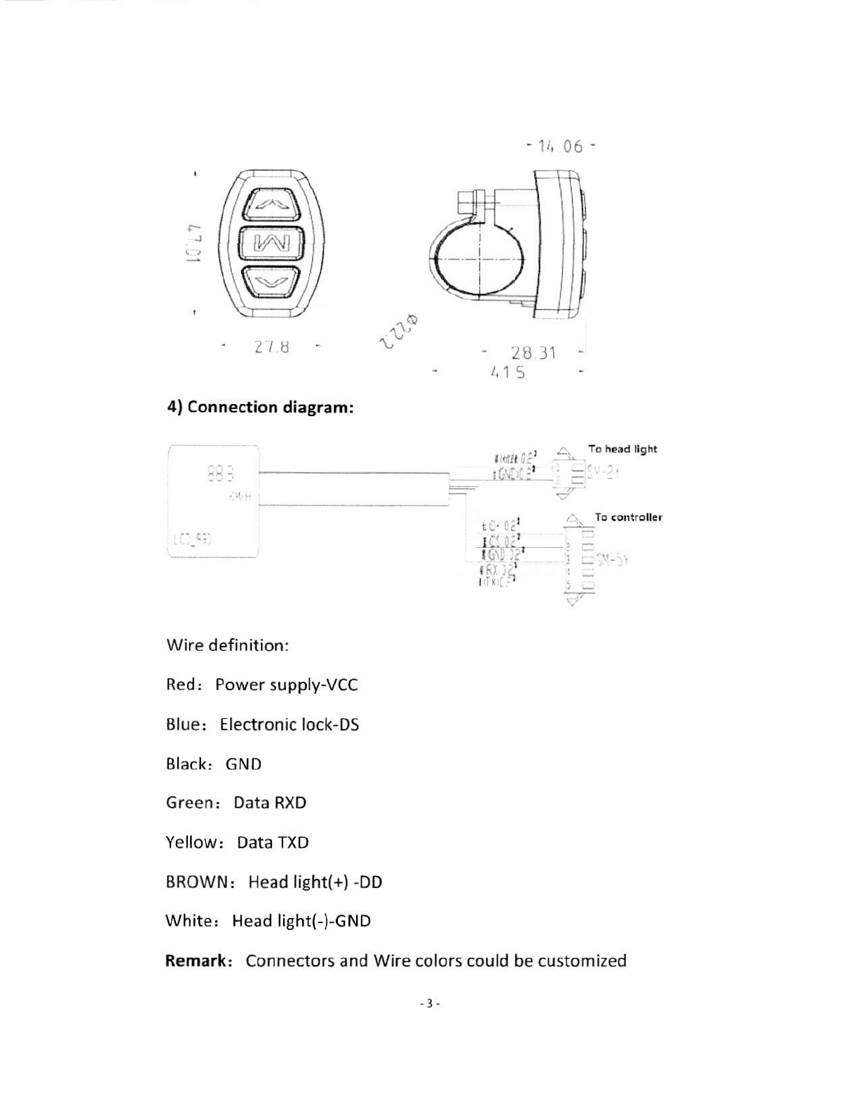
4) Connection diagram:
- 28 l1
i.1Pad lighr
\7
::'-i;'
Wire definition:
Red: Power supply-VCC
Blue: Electronic lock-DS
Black: cND
Green: Data RXD
Yellow: Data TXD
BROWN: Head light(+) -DD
White: Head light(-)-GND
Remark: Connectors and Wire colors could
-3-
be customized

5) lnstallation
a lnstall the display in the middle of handlebar, then
adjust to suitable angle, installthe press button to Ieft
side of handlebar.
O Power off the device, connect the device to controller.
o Power on
2. Overview of 5900
1) UART protocol::
Equipped with independent press buttons
2) Speed'
Real-time SPEED, MAX 5PEED, Average SPEED
3) kmh/mile:
Kmh/MPH according to habit
4) Battery level:
lndicates the battery level in realtime
S) Head light control:
Press button to power on/off

6) Back light adjustment:
3-level adjustment
7)Assist level:
From 0 to 5, press button to change assist level,o-no assist,
5-default value
8) Distance:
ODO/Trip/Driving duration
9) Error code:
Please refer to appendix table 1 for definition
10) 5km mode:
ln this mode, it will display "WALK" on the screen
11)Parameter setting,
set parameters, such as: wheel size, speed limit etc
-5

3. Presentation of screen
1) Speed, Average SPEED/MAX SPEED/Real-time sPEED
2) Speed unit: Kmh/MPH
3) Battery level:5levels, voltage interval could be customized
4) Head light icon ' indicates when head light and back light are on
5) Error code: "ERRoR" and code when there is error
6) Assist level, actual assist level 0-5,0-no assist, 1- Eco,2,3-STD,
4,5.POWER)
7) Distance: TriploDo
8) 6km mode
4. Press button definition
LCD-S900 uses independent press button, in totalthree
buttons:
-6-
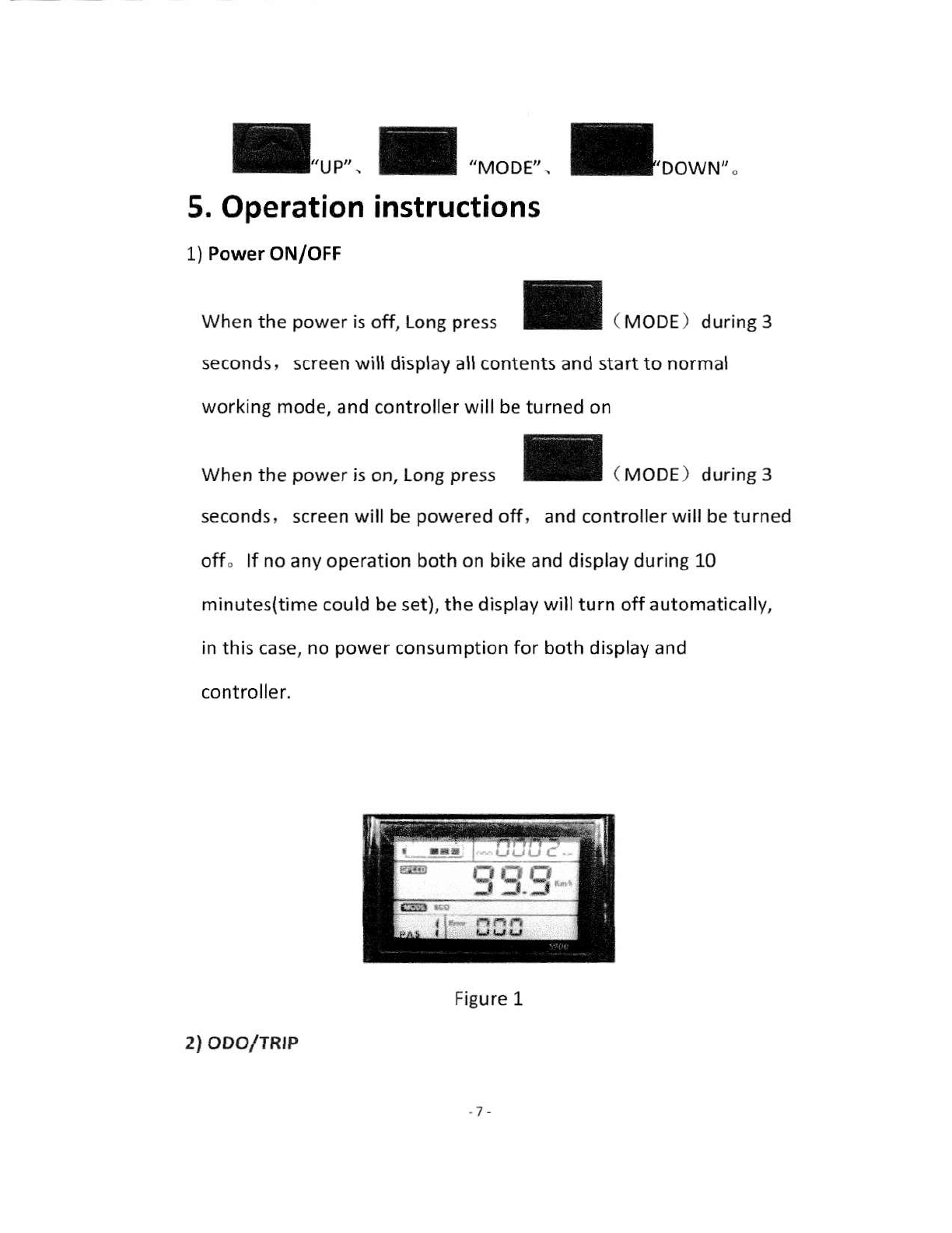
I-rr'. I',oo,". I'oo*r..
When the power is off, Long press
seconds, screen will displayall contents and start to normal
working mode, and controller will be turned on
I,ror, o,,.,nr,
I (M.DE) durins3
5. Operation anstructions
1) Power ON/OFF
When the power is on, Long press
seconds, screen will be powered off, and controller will beturned
off" lf no any operation both on bike and display during 10
minutes(time could be set), the display willturn off automatically,
in this case, no power consumption for both display and
controller.
Figure 1
a 93.9*
2l ODOlTRtP
1-

short press I,o r*,a.n oDo/TRrp , Trip(singretrip
distance))ODO(Accumulated distance)
Figure 2Figure 3
3) Assist level
,non orurrf ,, f to chanse assis.ever, defaurt
value is level 1
oDo
I
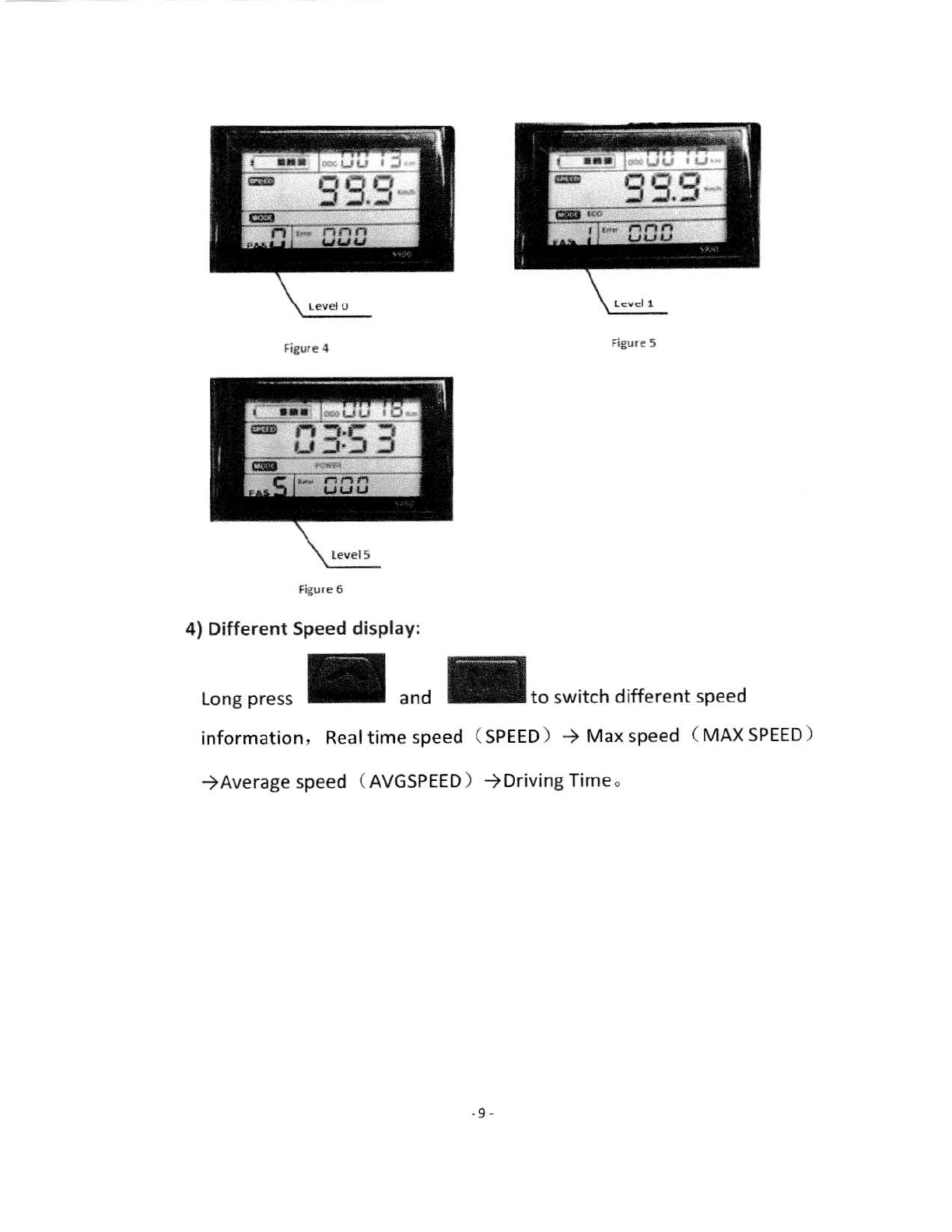
Figure6
4) Different Speed display:
Long press I ""0 I,o r*,,.n different speed
information, Real time speed
)Average speed ( AVGSPEED )
( SPEED ) ) Max speed ( MAX SPEED )
)Driving Time"
.9-

SPEED \i.,,ti slE:ir
AVG SPEED
5) Head light control
,on* or"rrl turn onloffthe head light"
6) 6km mode
-10

When the bike is stopped, long press l, will enter
6km/h mode, the speed will be 4.5-7.5km/h according to
different road conditions, "WALK" will show up on screen,
long press again I or short press I,',,,, or,,
6km/h mode. Long press or short press could be customized
by clients.
6. Parameter setting
When the display is powered on, long press L"o
, will enter parameter setting mode ( Figure 13 ) , in
this mode, can change parametervalues, long press again
I ""0 f witt quit parameter setting mode or
no operation during 10s will also quit this mode
'11.

ln parameter setting mode, short pre* f,I*,,,
change parameter value, short press I,,, save current
value and switch to next parameter
1) P01-back light Iightness:
,n"n or"*Irl witl switch from 1to 3,Levet 3 is
lightest. Level 2 is default value.
2) P02-kmh/MPH: '12 -

short press IIo switch kmh/MpH
3) P03-Working voltage:
short press
is 36V
o switch 24V,36V,48V, Default value
Figo.e t6
4) P04-Auto shutdown time
s hort press o switch from 0 to 60, it is the time(in
minutes) to shut down the screen automatically if no operation O means
never shut down, Default value is 10 minutes
13

tigure rl
5) P05-Number of Assist levels:
Short p
0:
1:
rigure 1A
6) P06-Wheel size selection,
.".II to chanse tevel o->1->2
3 assist levels
5 assist levels
9 assist levels
,nou or"rJl to switch wheel size, ininch, step: 0.1
inch
- 74.

Figure tO
7) Po7-Number of magnets for speed sensor:
,nor, rr".rJl to switch fromt 1to 1oo
8) Po8-speed limit:
,non or"rllo set the speed timit from 0 to 100Km/h,
0 means no limit
one m6g.et lor 5p.ed tetrtor
- 15,
Table of contents
Other Merkava Scooter manuals


Popular Scooter manuals by other brands

Fuzion
Fuzion Asphalt owner's manual

Heartway Medical Products
Heartway Medical Products S9 user manual

SoFlow
SoFlow SO1 PRO Instruction

Razor
Razor Electric Party POP owner's manual

Sunrise Medical
Sunrise Medical Sterling SAPPHIRE LS2 owner's manual

aidapt
aidapt Deluxe Scooter Poncho VA127CA Usage and maintenance instructions


