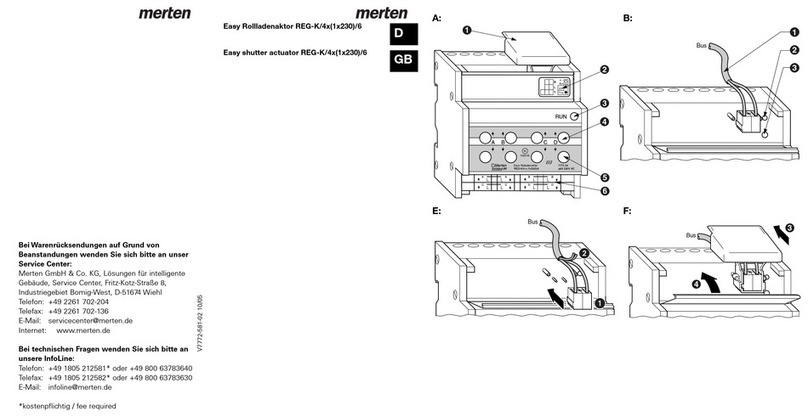
merten 6478 93 User manual

As at 11/03 1
Chapter 7: Switch actuators
7. 5 Switch actuator 8-fold
Switch actuator REG-K/8x230/16 with manual mode
Art. No. 6478 93
Switch actuator REG-K/8x230/16 with manual modeCh apter 7:Switch actuatorsArt. No.6478 93As at 11/037.5Switch actuator 8-fold
1. Fu n c t i o n 1
2. Installation 2
3. Commissioning 2
4. Technical data 3
5. Settings in the EIB Tool Software (ETS) 4
The INSTABUS switch actuator REG-K/8x230/16 with
manual mode is used for switching luminaires and
other loads via make contacts. The device has eight in-
dependent channels (A to H) available with potential-
free relay outputs and an integrated bus coupling unit.
The function of the channels is determined by the
downloaded application software.
Operating and display elements (Fig. !):
The green operating LED indicates that the device is
ready for operation. It only lights up if the application
program has been correctly loaded into the device.
The red programming LED lights up if the program-
ming button in the device has been pressed.
¼Danger due to electrical current:
Even if the manual switch is in the "OFF" positi-
on, a bus telegram can make the connections
live at any time. Before working on the device,
always disconnect from the supply via the back-
up fuse.
Using the 8 manual switches on the top of the device,
the switch outputs (switched outer conductor) can
also be manually switched without bus voltage. Switch
outputs A to H.
Switch actuator REG-K/8x230/16 with
manual mode
Article No.
6478 93
Table of Contents
G
OFF
H
OFF
RUN
OFFOFFOFFOFFOFF
FEDCBA
Schaltaktor REG-K/8x230/16
mit Handbet tigung
B
L
T
+--
ON
Bus
Prog.
instabus EIB
1000W 6478 93
AC 230V
16AX
LL LLLLLLLLLLLL
1. Function
ACable cover
BLabelling field
CBus terminal, max. 4 core pairs
DProgramming LED (red LED)
EProgramming button
FOperating LED (green LED)
GManual switch
LL
G
G
OFF
H
OFF
RUN
L
H
LL
F
LL
E
LL
D
LL
C
LL
B
LL
A
OFFOFFOFFOFFOFF
FEDCBA
Schaltaktor REG-K/8x230/16
mit Handbetätigung
B
L
T
+--
ON
Bus
Prog.
instabus EIB
1000W 6478 93
AC 230V
16AX
A
B
CD
E
F
G
!

As at 11/03 2
Chapter 7: Switch actuators
7. 5 Switch actuator 8-fold
Switch actuator REG-K/8x230/16 with manual mode
Art. No. 6478 93
½Caution:
Adjacent devices can be damaged! Only install
devices with at least basic insulation next to the
device.
Snapping onto the DIN rail (Fig. "):
1Place the device on the DIN rail from underneath
and push upwards (press the springs together)
2Press down at the top and hook onto the rail
|A data rail is not required.
Removal from the DIN rail (Fig. "):
3Push the device upwards (press the springs toge-
ther).
4Unhook the device from the DIN rail at the top and
remove the device
Bus connection (Fig. §):
1Connect the red bus wire to the red terminal (+)
and the black wire to the dark grey terminal (-).
2Shield and filler wire as well as the white and yel-
low wires of the bus cable are not required. Insula-
te and place in the cable cover
3Place the cable cover on the bus connection
4Close the flap
½Caution:
Safety clearance must be guaranteed in accor-
dance with DIN VDE 0110 part 1. A distance of
at least 4 mm must be maintained between in-
dividual cores of the 230 V cable and the bus ca-
ble.
Connection of the outputs:
¼Danger due to electrical current:
Vibrations during transport can enable the out-
puts. When connecting the mains voltage to the
system, voltage can lie at the outputs!
To de-energise the outputs:
After commissioning, carry out a switching cyc-
le (On/Off) via bus telegrams or set the manual
switch to “OFF”.
½Caution:
Switch actuator can be damaged. Protect the
switch contacts with a series-connected 16 A
circuit-breaker.
Connect the device according to the connection ex-
ample. The cables to the loads as well as the system
voltages (L1, L2 or L3) are connected via screw termi-
nals for max. 16 A. Every two L connections are
bridged internally.
(See Fig. %)
After wiring the device, the assignment of the physical
address and the parameterisation are carried out:
1Connect the interface to the bus
2Connect the bus voltage to the system
3Press the programming button in the device (red
LED lights up)
4Download the physical address from the ETS via
the interface (red LED is extinguished)
5Download the prepared application with the appro-
priate parameter settings into the device via the in-
terface (green LED lights up)
6Connect the mains voltage to the system
7When the device is ready for operation, check the
required function (also possible using ETS)
2. Installation
1
2
3
4
"
Bus
§
1
4
2
3
Bus
3. Commissioning
$

As at 11/03 3
Chapter 7: Switch actuators
7. 5 Switch actuator 8-fold
Switch actuator REG-K/8x230/16 with manual mode
Art. No. 6478 93
Connection example:
4. Technical data
External auxiliary supply: none
Power supply from the
bus:
DC 24 V / approx. 15 mA
Insulation voltage: AC 4 kV between bus and
230 V AC
Switch contacts A to H: 8 x make contacts, potenti-
al-free
Fuse: Protect the switch contacts
with a series-connected 16
A circuit-breaker
Nominal voltage: AC 230 V, 50 to 60 Hz
Nominal current: 16 A, cos ϕ= 0.6
Connected load:
Incandescent lamps: AC 230 V, max. 3600 W
with 10,000 switching cyc-
les
Halogen lamps: AC 230 V, max. 2500 W
with 10,000 switching cyc-
les
Fluorescent lamps: AC 230 V, max.2500 VA,
with parallel correction,
with 5,000 switching cyc-
les
Capacitive load: AC 230 V, 16 A max. 200 µF
with 5,000 switching cyc-
les
Minimum loads: 12 V DC/24 V AC, 100 mA
Nominal current (DC 12
V):
10 A
Switching frequency: max. 10 per minute at no-
minal load
Ambient temperature
Operation: -5 °C to+45 °C
Storage: -25 °C to+55 °C
Transport: -25 °C to+70 °C
Environment: The device is designed for
use at a height up to 2000
m above sea level
Max.humidity: 93 %, no moisture conden-
sation
Operating elements: Programming button, 8 ma-
nual switches for manual
mode
Display elements:
Programming check: 1 red LED
Readiness for opera-
tion:
1 green LED
Connections:
Bus: via two 1 mm pins for bus
terminal
Outer conductor: 7 x 3-fold screw terminals
(A - G) and
1 x 2-fold screw terminal
(H) for max. 2.5 mm2each
Device width: 8 modules = approx. 144
mm
EC guidelines: corresponds to low voltage
guideline 73/23/EEC, corre-
sponds to EMC guideline
89/336/EEC

As at 11/03 4
Chapter 7: Switch actuators
7. 5 Switch actuator 8-fold
Switch actuator REG-K/8x230/16 with manual mode
Art. No. 6478 93
Selection in the product database
|To guarantee the full functionality of the applica-
tions under ETS2, the ETS2 program from versi-
on 1.2 onwards and Service Release A or higher
should be used. If you have any queries, please
contact the Merten InfoLine.
The following applications are available:
Switch Logic Time Scene Disable Prio. Init.
480B/2.0
5. Settings in the EIB Tool Software (ETS)
Manufacturer: Merten
Product family: 4.42 Switch actuator, 8-fold
Product type: 4.42.02 DIN rail mounted REG-K
Program name: Switch Logic Time Scene Disable
Prio. Init.480B/2.0
Media type: Twisted Pair
Product name: Switch actuator REG-K/8x230/16
with manual mode
Order number: 6478 93
Application overview
Functional group Function
Group addresses Number of objects/associations
= 152, dynamic
Reset behaviour Behaviour on bus voltage failure
Behaviour on bus voltage reco-
very
Behaviour after ETS download
Relay operation Relay operation: break contact/
make contact/changeover con-
tact/flashing indicator
Switching function Switch
Central switching function
Time functions ON delay
OFF delay
ON and OFF delay
Staircase lighting function (stair-
case timer), retriggerable/not
retriggerable, with/without ma-
nual OFF function, prewarning
function
ON delay and staircase lighting
function
OFF delay and staircase lighting
function
Higher priority functions Disable function with/without
switching delay/staircase ligh-
ting function
Logic operation (AND/OR) or pri-
ority control
Scenes 1 byte scene function
Status information (status re-
sponse)
Active status response function
Passive status information
Other merten Controllers manuals
Popular Controllers manuals by other brands
LEGRAND
LEGRAND Wattstopper LMRC-611MCC quick start guide

Roller
Roller Control instruction manual
HID
HID VertX EVO V1000 installation guide

Aerotech
Aerotech A3200 Series Hardware manual

Watlow
Watlow Ramping and Profiling Microprocessor-Based Control SERIES... user manual
AirTek
AirTek NFT28U quick start guide
