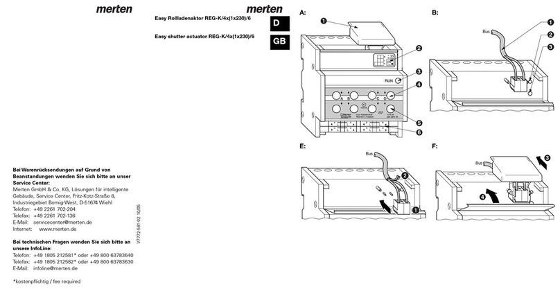
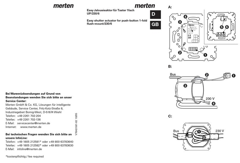
merten 7641 94 User manual

D
GB
Easy Schaltaktor für ARGUS 180
UP/230/10
Easy switching actuator for ARGUS 180
flush-mount/230/10
A: B:
C: D:
Merten
Easy Schaltaktor
f r ARGUS 180
UP/230/10
7641 94
B
L
T
instabus
'
EIB
1
3
4
2
56
Bus
230 V
1
2
3
4
230 V
Bus
1
LN
-
Bus
+
10A
-
+
10 pol.
1
2
H:
V7641-584-0212/05
764194_u.fm Seite 1 Dienstag, 15. Oktober 2002 11:19 11
Bei Warenrücksendungen auf Grund von
Beanstandungen wenden Sie sich bitte an unser
Service Center:
Merten GmbH & Co. KG, Lösungen für intelligente
Gebäude, Service Center, Fritz-Kotz-Straße 8,
Industriegebiet Bomig-West, D-51674 Wiehl
Telefon: +49 2261 702-204
Telefax: +49 2261 702-136
E-Mail: ser[email protected]
Bei technischen Fragen wenden Sie sich bitte an
unsere InfoLine:
Telefon: +49 1805 212581* oder +49 800 63783640
Telefax: +49 1805 212582* oder +49 800 63783630
E-Mail: [email protected]
*kostenpflichtig / fee required
Internet: www.merten.de

E:
1
2
3
6
4
5
8 m
7
65
4321
0
1 m
87654321 8 m7654321
8
7
6
5
4
3
2
1
0
m
0
2
3
1
F:
G:
G:
I:
764194_u.fm Seite 2 Dienstag, 15. Oktober 2002 11:19 11

D
GB
1
Gebrauchsanweisung 2
Operating instructions 19
Anleitung_764194.book Seite 1 Dienstag, 15. Oktober 2002 11:21 11
2
Artikel-Nr. 7641 94
Bild A:
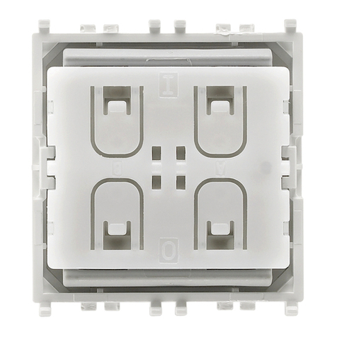
➊Schnittstelle, 10polig
➋Programmiertaste, manuell
➌Rote LED, Programmierkontrolle
➍Beschriftungsfeld
➎Busanschlussklemme, max. 4 Adern-
paare
➏Schraubklemme, 2polig, für 230 V
Netzleitung (L, geschaltet)
Für Anwendungsmodul ARGUS 180 UP
(OCTOCOLOR 6215 .. oder System Fläche
6214 .. oder System M 6243 ..)
Easy Schaltaktor für ARGUS 180
UP/230/10
Anleitung_764194.book Seite 2 Dienstag, 15. Oktober 2002 11:21 11
3
Der Easy Schaltaktor für ARGUS 180
UP/230/10 ist nur verwendbar in Verbin-
dung mit dem EIB Easy Basisgerät (Artikel-
Nr. 7900 29) oder einem anderen externen
EIB Easy Einstellgerät.
Zusätzlich zur 230 V Netzleitung benötigt
der Easy Schaltaktor für ARGUS 180
UP/230/10 eine Busleitung. Informationen
zur Verlegung der Busleitung finden Sie in
der Bedienungsanleitung „Basisgerät“ und
im ZVEI/ZVEH Handbuch „Gebäudesy-
temtechnik, Grundlagen“ (Artikel-Nr.
6160 01).
Es gelten die einschlägigen Normen,
Richtlinien, Vorschriften und Bestimmun-
gen des jeweiligen Landes. Arbeiten am
Installationsbus dürfen nur von Elektro-
Fachkräften ausgeführt werden. Gerät bei
Transport, Lagerung und im Betrieb vor
Feuchtigkeit, Schmutz und Beschädigung
schützen. Gerät nicht außerhalb der spezi-
fischen technischen Daten betreiben.
Wichtiger Hinweis
Anleitung_764194.book Seite 3 Dienstag, 15. Oktober 2002 11:21 11

4
Die Software, die den Schaltaktor und den
Sensor miteinander kommunizieren lässt,
ist in die Funktionsbereiche „Aktorteil“ und
„Sensorteil“ unterteilt. Beide Funktionsbe-
reiche können miteinander, aber auch völ-
lig unabhängig voneinander betrieben
werden.
Damit ist eine größtmögliche Flexibilität bei
der Installation und den Anwendungen ge-
währleistet.
Hieraus ergeben sich mehrere Möglichkei-
ten, um den Schaltaktor zu betreiben (sie-
he auch Montagevorschlag):
1. Das Anwendungsmodul ARGUS 180
UP wird auf den Schaltaktor aufge-
steckt und steuert diesen an.
2. Als allein stehendes Gerät. In diesem
Fall erfolgt die Ansteuerung des Schalt-
aktors über einen Taster an anderer
Stelle. Der Aktor wird mit einer Blindab-
deckung abgedeckt (Art.-Nr. 6622 ..,
6620 .. oder 6621 ..).
Nachfolgend werden die Funktionsberei-
che „Aktorteil“ und „Sensorteil“ genauer
beschrieben.
Funktionen
Anleitung_764194.book Seite 4 Dienstag, 15. Oktober 2002 11:21 11
5
Im Aktorteil verfügt der Easy Schaltaktor
für ARGUS 180 UP/230/10 über einen
schaltbaren Relaisausgang und ermöglicht
das Schalten von Beleuchtungskörpern
und anderen Verbrauchern. Der Easy
Schaltaktor für ARGUS 180 UP/230/10 hat
drei Funktionen, die am Basisgerät einge-
stellt werden:
- Schalten
Das Ein- / Ausschalten des an den Schalt-
aktor angeschlossenen Verbrauchers wird
bei dieser Funktion durch Betätigen eines
zugeordneten Tasters ausgelöst (z. B. Tas-
terbetätigung oben/links = Ein und Taster-
betätigung unten/rechts = Aus).
- Zeitfunktion
In der Zeitfunktion (entspricht Treppen-
hausautomat) erhält der Schaltaktor ein Si-
gnal vom ARGUS (Sensorteil). Sobald er
dieses Signal erhält, startet er die gewählte
Einschaltzeit, das Licht wird eingeschaltet.
Nach Ablauf der Einschaltzeit wird das
Licht automatisch ausgeschaltet. Erhält
der Schaltaktor vor Ablauf der Einschalt-
zeit ein weiteres Signal, startet er die Ein-
schaltzeit erneut.
Funktionen Aktorteil
Anleitung_764194.book Seite 5 Dienstag, 15. Oktober 2002 11:21 11
6
Die Einschaltzeit kann in Stufen von 1 Se-
kunde bis 24 Stunden am Basisgerät para-
metriert werden.
- Zwangsführung
Die Funktion „Zwangsführung“ ist eine Si-
cherheitsfunktion. Sie sperrt im entspre-
chenden Aktor die Schalt- und die
Zeitfunktion, bis sie wieder deaktiviert
wird, z. B. für Dauerlicht im Treppenhaus.
Zwang ein/aus: Taster oben/links
Zwang deaktivieren: Taster unten/rechts
Der Sensorteil bildet zusammen mit dem
aufgestellten Anwendungsmodul ARGUS
180 UP den Bewegungsmelder. Der Bewe-
gungsmelder (Easy Schaltaktor für ARGUS
180 UP/230/10 mit Anwendungsmodul
ARGUS 180 UP) ist für den lnnenbereich
ausgelegt. Er erfasst Bewegungen inner-
halb eines Winkels von 180° bis zu einer
Entfernung von 8 m. Registriert der AR-
GUS Bewegungen sendet er zyklisch Sig-
nale an den Schaltaktor (Aktorteil).
Funktionen Sensorteil
Anleitung_764194.book Seite 6 Dienstag, 15. Oktober 2002 11:21 11

7
- Abschaltbare Bewegungserkennung
Damit der ARGUS das Ausschalten einer
Leuchte nicht als Bewegung interpretiert,
wird die Bewegungserkennung für ca. 2 s
gesperrt.
- Lichtabhängige Bewegungserken-
nung
Bei dieser Funktion werden Bewegungen
nur dann erkannt, wenn das Licht bereits
manuell über einen Taster eingeschaltet
worden ist. Werkseitig ist die Funktion auf
„ausgeschaltet“ gestellt. Die Einstellung
erfolgt am Basisgerät unter dem Parame-
ter „Bewegung halten“.
- Sperrfunktion
Mit dieser Funktion kann der ARGUS funk-
tional abgeschaltet werden.
- Einstellbare Zykluszeit
Die Zykluszeit ist stufenweise von 10 s bis
5 min am Basisgerät einstellbar.
- Helligkeitsauswertung
Der ARGUS erkennt nur dann Bewegun-
gen, wenn die Helligkeitsschwelle unter-
schritten wird.
Anleitung_764194.book Seite 7 Dienstag, 15. Oktober 2002 11:21 11
8
Elektrischer Anschluss
Achtung
Der Schaltausgang verfügt über ein bista-
biles Relais. Der Schaltkontakt des Relais-
ausgangs kann durch starke
Erschütterungen beim Transport in den
durchgeschalteten Zustand wechseln.
Beim Zuschalten der Netzspannung kann
an dem Relaisausgang Spannung anlie-
gen!
Hinweis
Die Umgebungstemperatur ist zu be-
achten, siehe „Technische Daten“.
Installationsvorschlag:
Bild B:
➊Die rote Busader an die rote Klemme
(+) und schwarze an die dunkelgraue
Klemme (-) anschließen.
➋Schirm und Beilaufdraht sowie weiße
und gelbe Ader der Busleitung werden
nicht benötigt. Isolieren und in Unter-
putzdose unterbringen.
➌Wanddose, DIN 49 073, Form B,
ø60mm
Montage
Anleitung_764194.book Seite 8 Dienstag, 15. Oktober 2002 11:21 11
9
➍Der Anschluss der 230 V Netzleitung
(L, geschaltet) erfolgt über eine 2polige
Schraubklemme.
Hinweis
Den Montagevorschlag auf der folgen-
den Seite beachten.
Bild C:
Beim Anschluss der 230 V Netzleitung und
der Busleitung ist darauf zu achten, dass
die isolierten Einzeladern der 230 V Netz-
leitung zu denen der Busleitung einen Min-
destabstand von 4 mm einhalten.
Um den Mindestabstand von 4 mm zu
sichern, muss folgendes beachtet werden:
- Für die 230 V Netzleitung und die Bus-
leitung sind die gegenüberliegenden
Einführungsöffnungen der Installati-
onsdose zu verwenden.
- Der Mantel der Busleitung sollte so
kurz wie möglich (Mantellänge = 12
mm, Abisolierlänge = 6 mm) an der
Busanschlussklemme abgesetzt wer-
den.
- Die beiliegenden, flexiblen Isolier-
schläuche ➊ werden über die einzel-
nen 230 V Leitungen geschoben.
Anleitung_764194.book Seite 9 Dienstag, 15. Oktober 2002 11:21 11

10
Weitere Informationen zur Verlegung der
Busleitung finden Sie in der Bedienungs-
anleitung „Basisgerät“ und im ZVEI/ZVEH-
Handbuch „Gebäudesystemtechnik“,
Grundlagen (Art.-Nr. 6160 01).
Anschlussbeispiel:
Bild D:
➊Easy Schaltaktor für ARGUS 180
UP/230/10
➋Anwendungsmodul ARGUS 180 UP
Montagevorschlag:
Bild E:
➊Wanddose, DIN 49 073, Form B,
ø 60 mm
➋Easy Schaltaktor für ARGUS 180
UP/230/10
➌Rahmen
➍Anwendungsmodul ARGUS 180 UP
➎Blindabdeckung
Der Easy Schaltaktor für ARGUS 180
UP/230/10 kann auch ohne Anwen-
dungsmodul ARGUS 180 UP montiert
werden. Hierbei Blindabdeckung Art.
Nr. 6622 .. / 6620 .. / 6621 .. verwen-
den.
Anleitung_764194.book Seite 10 Dienstag, 15. Oktober 2002 11:21 11
11
Easy Schaltaktor für ARGUS 180
UP/230/10 ➋gemäß Anschlussbeispiel
anschließen und auf Wanddose ➊mit bei-
gelegten Schrauben ➏aufschrauben.
Anwendungsmodul ARGUS 180 UP ➍zu-
sammen mit Rahmen ➌auf Easy Schalt-
aktor für ARGUS 180 UP/230/10 ➋auf-
stecken.
Montagehöhe:
Bild F:
Die optimale Montagehöhe ist 1 m -
1,50 m. Alle davon abweichenden Maße
haben stark veränderte Reichweiten zur
Folge.
Erfassungsbereich:
Bild G:
Vermeidung ungewollter Schaltvor-
gänge:
- Den ARGUS auf einem festen Unter-
grund montieren.
- Werden geschaltete Leuchten im Er-
fassungsbereich des ARGUS montiert,
muß ausreichend Abstand gehalten
werden. Das kann bei hoher An-
schlussleistung bis 3 m sein.
Anleitung_764194.book Seite 11 Dienstag, 15. Oktober 2002 11:21 11
12
- Die Montage des ARGUS oberhalb ei-
ner Leuchte vermeiden. Die Wärme-
strahlung der Leuchte kann die
Funktion des Bewegungsmelders be-
einflussen und ggf. zu einer dauerhaf-
ten Lichteinschaltung führen.
- Störquellen, wie z. B. Kaminfeuer, offe-
ne Fenster, sollten außerhalb des Er-
fassungsbereiches des ARGUS liegen.
Optimale Bewegungsüberwachung:
Bild H:
Hinweis:
Den ARGUS an solchen Stellen mon-
tieren, die maximale Bewegungsüber-
wachung ermöglichen.
Anbringung mehrerer ARGUS:
Werden mehrere ARGUS zur Überwa-
chung einer langen Front nebeneinander
montiert, ist darauf zu achten, dass sich
die Strahlengänge der einzelnen Bewe-
gungsmelder überschneiden. Nur so lässt
sich eine lückenlose Überwachung sicher-
stellen.
Montagerichtung:
Bild I:
➊Richtig
➋Nicht optimal
➌Falsch
Anleitung_764194.book Seite 12 Dienstag, 15. Oktober 2002 11:21 11

13
Für eine optimale Bewegungserfassung
muß der ARGUS seitlich zur Gehrichtung
montiert werden. Montageorte, bei denen
sich die zu erfassenden Objekte direkt auf
den ARGUS zu bewegen, haben eine star-
ke Reduzierung der Reichweite zur Folge.
Nach der Verdrahtung des Gerätes Bus-
spannung zuschalten.
Automatische Erkennung:
Im Easy Basisgerät den Menüpunkt „Neue
Funktion“ oder „Funktion bearbeiten“ wäh-
len.
Das Gerät wird automatisch durch das Ba-
sisgerät erkannt und in der Kanalliste mit
der vergebenen Gerätenummer angezeigt.
Manuelle Erkennung:
Ist das Gerät nicht mehr im Auslieferungs-
zustand, so ist zur Erkennung die Pro-
grammiertaste kurz (< 2 Sekunden) zu
betätigen. Die rote LED leuchtet während
des Erkennungsvorganges.
Inbetriebnahme am Easy Basisgerät
Anleitung_764194.book Seite 13 Dienstag, 15. Oktober 2002 11:21 11
14
Das Gerät wird durch das Basisgerät er-
kannt und in der Kanalliste mit der verge-
benen Gerätenummer angezeigt.
Inbetriebnahme:
Ist das Gerät erkannt worden, so erscheint
der Kanal des Gerätes in der Kanalüber-
sicht des Easy Basisgerätes.
Für die Verbindung (Auswahl) des Schalt-
aktorkanals die Programmiertaste lang (> 2
Sekunden) betätigen. Der Schaltaktor
schaltet dabei ein bzw. aus.
Hinweis
Die rote LED (Programmierkontrolle)
muss vor Betätigen der Programmier-
taste ausgeschaltet sein. Der Kanal
wird in der Kanalübersicht markiert.
Für die Verbindung (Auswahl) des ARGUS
die Programmiertaste lang (> 2 Sekunden)
betätigen.
Hinweis
Die rote LED (Programmierkontrolle)
muss vor Betätigen der Programmier-
taste eingeschaltet sein. Der Kanal wird
in der Kanalübersicht markiert.
Anleitung_764194.book Seite 14 Dienstag, 15. Oktober 2002 11:21 11
15
Weiterführende Informationen finden Sie in
der Bedienungsanleitung des Easy Basis-
gerätes oder in den entsprechenden Doku-
mentationen zu anderen externen EIB Easy
Einstellgeräten.
Verhalten bei Anlegen/Wiederkehr
der Busspannung
17 s nach Busspannungswiederkehr ist
der ARGUS betriebsbereit.
Das Relais ist geöffnet.
Verhalten bei Ausfall der Busspannung
Keine Reaktion.
Einstellbare Parameter Aktor
(am Basisgerät einstellbar)
Einschaltzeit:
ausgeschaltet
1 s
2 s
3 s
5 s
10 s
15 s
20 s
30 s
45 s
1 min1)
1 min 15 s
1 min 30 s
2 min
2 min 30 s
3 min
5 min
15 min
20 min
30 min
1 h
2 h
3 h
5 h
12 h
24 h
Anleitung_764194.book Seite 15 Dienstag, 15. Oktober 2002 11:21 11

16
Einstellbare Parameter Sensor
(am Basisgerät einstellbar)
Zykluszeit:
Lichtabhängige Bewegungserkennung
(Menü „Bewegung halten“)
1) Werkseinstellung
10 s
30 s
45 s1)
1 min
2 min
5 min
ausgeschaltet1)
eingeschaltet
Technische Daten
Easy Schaltaktor für ARGUS 180 UP/230/10
Busversorgung: 24 V / I < 10 mA (abhängig
von Anwendungsmodul)
Umgebungstemperatur:
Betrieb:
Lagerung:
Transport:
-5 °C bis +45 °C
-25 °C bis +55 °C
-25 °C bis +70 °C
Das Gerät ist für eine Ein-
satzhöhe bis 2000 m über
Meeresspiegel (MSL) aus-
gelegt.
Bedienelement: Programmiertaste, manuell
Anzeigeelement: 1 rote LED, Programmier-
kontrolle
Anleitung_764194.book Seite 16 Dienstag, 15. Oktober 2002 11:21 11
17
Anschlüsse: Busanschlussklemme über
zwei 1 mm Stifte
Schnittstelle, 10 polig
Außenleiter über zwei
Schraubklemmen für
max 2 x 1,5 mm2 oder 1 x
2,5 mm2
Isolationsspannung: 4 kV AC zwischen Bus und
230 V AC
Schaltkontakt: 1 x Schließer, potentialfrei
Nennspannung: AC 230 V, 50 bis 60 Hz
Belastung:
ohmsche:
induktive:
kapazitive:
230 V~, 16 A, cos ϕ= 1
230 V~, 10 A, cos ϕ= 0,6
230 V~, 10 A, <140 µF
Anschlussleistung:
Glühlampen:
Halogenlampen
230 V~:
NV-Halogenlampen mit
Trafo:
NV-Halogenlampen mit
el. Trafo:
Leuchtstofflampen:
unkompensiert:
parallelkompensiert:
Duo-Schaltung:
230 V~, 2300 W/VA
230 V~, 2300 W
230 V~, 2000 W
230 V~, 500 VA
230 V~, 1500 W
230 V~, 10 A, C <140 µF
230 V~, 900 W
230 V~, 320 W
230 V~, 1500 W
Einbaubreite: Geeignet für 60er Unter-
putzdose
EG-Richtlinien: Entspricht Niederspan-
nungsrichtlinie 73/23/EWG
Entspricht EMV-Richtlinie
89/336/EWG
Anleitung_764194.book Seite 17 Dienstag, 15. Oktober 2002 11:21 11
18
Anwendungsmodule, Art.-Nr. 6214 ../6215 ..
Überwachungsbereich: 180°
Reichweite: 8 m
Anzahl der Ebenen: 1
Anzahl der Zonen: 14/12
Schutzart: IP20
Anleitung_764194.book Seite 18 Dienstag, 15. Oktober 2002 11:21 11

19
Article no. 7641 94
Fig. A:
➊Interface, 10-pin
➋Programming key, manual
➌Red LED, programming control
➍Labelling field
➎Bus supply terminal, max. 4 pairs of
wires
➏Screw terminal, 2-pin, for 230 V power
line (L, switched)
For application module ARGUS 180 flush-
mount (OCTOCOLOR 6215 .. or System
Design 6214 .. or System M 6243 ..)
Easy switching actuator for ARGUS
180 flush-mount/230/10
Anleitung_764194.book Seite 19 Dienstag, 15. Oktober 2002 11:21 11
20
The Easy switching actuator for ARGUS
180 flush-mount/230/10 can only be used
in conjunction with the EIB Easy base unit
(Article no. 7900 29) or another external
EIB Easy setting device.
In addition to the 230 V power line, the
Easy switching actuator for ARGUS 180
flush-mount/230/10 requires a bus line. In-
formation on laying the bus line can be
found in the "base unit" operating instruc-
tions and in the ZVEI/ZVEH "Building man-
agement system, Basic principles"
handbook.
The relevant norms, guidelines, rules and
regulations of each country apply. Any
work on the installation bus must only be
carried out by qualified electricians. The
device should be protected against mois-
ture, dirt and damage during transporta-
tion, storage and operation. Do not operate
the device beyond the specified technical
data.
Important advice
Anleitung_764194.book Seite 20 Dienstag, 15. Oktober 2002 11:21 11
21
The software that lets the switching actua-
tor and the sensor communicate with each
other is divided into the functional areas
"actuator component" and "sensor com-
ponent". Both functional areas can be op-
erated together, but also completely
independently from each other. This guar-
antees maximum flexibility for the installa-
tion and the applications. This means there
are several possibilities for operating the
switching actuator (see also Assembly pro-
posal):
1. The ARGUS 180 flush-mount applica-
tion module is attached to the switch-
ing actuator and controls it.
2. As a stand-alone device. In this case,
the switching actuator is controlled via
a push-button located elsewhere. The
actuator is covered with a blinding cov-
er (Art. no. 6622 .., 6620 .. or 6621 ..).
The functional areas "actuator compo-
nent" and "sensor component" are de-
scribed in more detail below.
Functions
Anleitung_764194.book Seite 21 Dienstag, 15. Oktober 2002 11:21 11

22
In the actuator component, the Easy
switching actuator for ARGUS 180 flush-
mount/230/10 has a switchable relay out-
put and enables the switching of lighting
appliances and other loads. The Easy
switching actuator for ARGUS 180 flush-
mount/230/10 has three functions, the set-
tings for which are made on the base unit:
- Switching
With this function, the on/off switching of
the load connected to the switching actua-
tor is triggered by pressing an assigned
push-button (e.g. press push-button top/
left push-button = On and press push-but-
ton bottom/right push-button = Off).
- Timer mode
In the timer mode (corresponds to stair-
case automatic function), the switching ac-
tuator receives a signal from the ARGUS
(sensor component). As soon as it receives
this signal, it starts the selected switch-on
time, and the light is switched on. When
the switch-on time has elapsed, the light is
automatically switched off. If the switching
actuator receives another signal before the
switch-on time has elapsed, it starts the
switch-on time again.
Actuator component
Anleitung_764194.book Seite 22 Dienstag, 15. Oktober 2002 11:21 11
23
The parameters for the switch-on time can
be set incrementally from 1 second to 24
hours on the base unit.
- Priority control
The "priority control" function is a safety
function. It locks the switching function
and the timer mode in the relevant actuator
until it is deactivated again, e.g. for con-
stant light in the staircase.
Priority on/off: top/left push-button
Deactivate priority: bottom/right
push-button
The sensor component, together with the
configured ARGUS 180 flush-mount,
forms the movement detector. The move-
ment detector (Easy switching actuator for
ARGUS 180 flush-mount/230/10 with AR-
GUS 180 flush-mount application module)
is designed for use indoors. It detects
movements within a range of 180° up to a
distance of 8 m. If the ARGUS detects
movements, it transmits signals cyclically
to the switching actuator (actuator compo-
nent).
Sensor component
Anleitung_764194.book Seite 23 Dienstag, 15. Oktober 2002 11:21 11
24
- Movement detection can be
switched off
To ensure that the ARGUS does not inter-
pret a light being switched off as a move-
ment, movement detection is blocked for
approx. 2 s.
- Light-dependent movement detection
With this function, movements are only de-
tected if the light has already been
switched on manually via a push-button.
The factory setting for this function is "dis-
abled". The setting is made on the base
unit under the parameter "Keep move. ap-
plica.".
- Block function
With this function, the ARGUS can be
functionally switched off.
- Adjustable cycle time
The cycle time is adjustable incrementally
from 10 s to 5 min on the base unit.
- Brightness evaluation
The ARGUS only detects movements if the
brightness threshold is not exceeded.
Anleitung_764194.book Seite 24 Dienstag, 15. Oktober 2002 11:21 11

25
Electrical connection
Caution
The switch output has a bistable relay.
Strong vibrations during transportation can
cause the switching contact of the relay
output to change to the switched on state.
When connecting to the mains, the relay
output may contain a voltage!
Note
The ambient temperature should be
observed, see "technical data".
Installation proposal:
Fig. B:
➊Connect the red bus wire to the red
terminal (+) and the black one to the
dark grey terminal (-).
➋The screen and the stability wire as
well as the white and yellow wires of
the bus line are not required. Insulate
and put in flush-mounted box.
➌Wall box, DIN 49 073, Form B,
ø60mm
Montage
Anleitung_764194.book Seite 25 Dienstag, 15. Oktober 2002 11:21 11
26
➍The 230 V power line (L, switched) is
connected via a 2-pin screw terminal.
Note
Follow the assembly proposal on the
following page.
When connecting the 230 V power line and
the bus line, ensure that there is a mini-
mum gap of 4 mm between the individual
insulated wires of the 230 V line and those
of the bus line.
To ensure the 4 mm minimum gap, the fol-
lowing points must be observed:
- The input openings on opposite sides
of the installation box should be used
for the 230 V power line and the bus
line.
- As little as possible of the casing of the
bus line should be stripped at the bus
supply terminal (casing length =
12 mm, stripped length = 6 mm).
- The enclosed flexible sleeving ➊is
pushed over the individual 230 V lines.
Anleitung_764194.book Seite 26 Dienstag, 15. Oktober 2002 11:21 11
27
Further information on laying the bus line
can be found in the "base unit" operating
instructions and in the ZVEI/ZVEH "Build-
ing management system, Basic principles"
handbook.
Connection example:
Fig. D:
➊Easy switching actuator for ARGUS
180 flush-mount/230/10
➋ARGUS 180 flush-mount application
module
Assembly proposal:
Fig. E:
➊Wall box, DIN 49 073, Form B, ø 60
mm
➋Easy switching actuator for ARGUS
180 flush-mount/230/10
➌Frame
➍ARGUS 180 application module
➎Blinding cover
The Easy switching actuator for
ARGUS flush-mount/230/10 can also
be installed without the ARGUS 180
flush-mount application module. In this
case, use the blinding cover, Art. no.
6622 .. / 6620 .. / 6621 ..
Anleitung_764194.book Seite 27 Dienstag, 15. Oktober 2002 11:21 11

28
Connect the Easy switching actuator for
ARGUS 180 flush-mount/230/10 ➋as
shown in the connection example and
screw onto the wall box ➊using the en-
closed screws ➏.
Attach the ARGUS 180 flush-mount appli-
cation module ➍, together with the frame
➌, to the Easy switching actuator for AR-
GUS 180 flush-mount/230/10 ➋.
Installation height:
Fig. F:
The optimal installation height is 1 m -
1.5 m. Any deviations from this height will
have a significant effect on the range.
Surveillance range:
Fig. G:
Avoidance of unwanted switching proc-
esses:
- Install the ARGUS on a firm base.
- If switched lights are being installed in
the surveillance range of the ARGUS,
an adequate space must be left. This
can be up to 3 m for high connected
loads.
Anleitung_764194.book Seite 28 Dienstag, 15. Oktober 2002 11:21 11
29
- Avoid installing the ARGUS above a
light. The heat radiated by the light can
influence the function of the movement
detector and may lead to the light being
switched on permanently.
- Sources of interference such as fire-
places, open windows, should lie out-
side the surveillance range of the
ARGUS.
Optimal movement monitoring:
Fig. H:
Note:
Install the ARGUS in locations that al-
low maximum movement monitoring.
Installing several ARGUS detectors:
If several ARGUS detectors are installed
next to each other in order to monitor a
long frontage, you should ensure that the
beam ranges of the individual movement
detectors overlap. This is the only way of
ensuring complete monitoring coverage.
Installation direction:
Fig. I:
➊Right
➋Not optimal
➌Wrong
Anleitung_764194.book Seite 29 Dienstag, 15. Oktober 2002 11:21 11
30
For optimal movement detection, the AR-
GUS should be installed at right angles to
the direction of movement. Installation
sites where the objects being detected are
moving directly towards the ARGUS result
in a sharp reduction in the range.
After wiring the device, switch on the bus
voltage.
Automatic recognition:
Choose the menu option "New function" or
"Edit function" in the Easy base unit.
The device is automatically recognised by
the base unit and displayed in the channel
list with the allocated device number.
Manual recognition:
If the device is no longer in the delivery sta-
tus, you should press the programming
key briefly (< 2 seconds) for recognition.
The red LED lights up during the recogni-
tion process.
Start-up with the Easy base unit
Anleitung_764194.book Seite 30 Dienstag, 15. Oktober 2002 11:21 11

31
The device is recognised by the base unit
and displayed in the channel list with the
allocated device number.
Start-up:
If the device has been recognised, the
channel of the device appears in the
channel overview of the Easy base unit.
To connect (select) the switching actuator
channel, press the programming key for
longer (> 2 seconds). This causes the
switching actuator to switch on or off.
Note
The red LED (programming control)
must be off before pressing the pro-
gramming key. The channel is marked
in the channel overview.
To connect (select) the ARGUS, press the
programming key for longer (> 2 seconds).
Note
The red LED (programming control)
must be on before pressing the pro-
gramming key. The channel is marked
in the channel overview.
Anleitung_764194.book Seite 31 Dienstag, 15. Oktober 2002 11:21 11
32
Further information can be found in the op-
erating instructions for the Easy base unit
or in the relevant documents for other ex-
ternal EIB Easy setting devices.
Behaviour when bus voltage is estab-
lished/returns
The ARGUS is ready for use 17 s after the
bus voltage has returned.
The relay is open.
Behaviour when bus voltage fails
No reaction.
Adjustable actuator parameters
(adjustable on base unit)
Switch-on time::
disabled
1 s
2 s
3 s
5 s
10 s
15 s
20 s
30 s
45 s
1 min1)
1 min 15 s
1 min 30 s
2 min
2 min 30 s
3 min
5 min
15 min
20 min
30 min
1 h
2 h
3 h
5 h
12 h
24 h
Anleitung_764194.book Seite 32 Dienstag, 15. Oktober 2002 11:21 11
33
Adjustable sensor parameters
(adjustable on base unit)
Cycle-time:
Light-dependent movement detection
("Keep move. applica." menu)
1)Factory setting
10 s
30 s
45 s1)
1 min
2 min
5 min
disabled1)
enabled
Technical-data
Easy switching actuator for ARGUS 180 flush-
mount/230/10
Bus supply: 24 V / I < 10 mA (depen-
dent on application
module)
Ambient temperature:
Operation:
Storage:
Transport:
-5 °C to +45 °C
-25 °C to +55 °C
-25 °C to +70 °C
The device is designed for
use at a height of up to
2000 m above sea level
(MSL).
Control elements: Programming key, manual
Displayelement: 1 red LED,
Programming control
Anleitung_764194.book Seite 33 Dienstag, 15. Oktober 2002 11:21 11

34
Connection: Bus supply terminal via
two 1 mm pins
Interface, 10-pin
Outer conductor via two
screw terminals for
max.2x1.5mmor
1x2.5mm
2
Insulation voltage: 4 kV AC between bus and
230 V AC
Switching contact: 1 x make contact,
voltage-free
Nominal voltage: AC 230 V, 50 to 60 Hz
Load:
ohmic::
inductive:
capacitive:
230 V~, 16 A, cos ϕ= 1
230 V~, 10 A, cos ϕ= 0,6
230 V~, 10 A, <140 µF
Connected load:
Incandescent lamps:
Halogen lamps
230 V~:
NV halogen lamps with
transformer:
NV halogen lamps with
(el.) transformer:
Fluorescent lamps:
uncorrected:
parallel-corrected:
Duo circuit:
230 V~, 2300 W/VA
230 V~, 2300 W
230 V~, 2000 W
230 V~, 500 VA
230 V~, 1500 W
230 V~, 10 A, C <140 µF
230 V~, 900 W
230 V~, 320 W
230 V~, 1500 W
Device width: Suitable for a size 60 flush-
mounted box
EC Directives: Complies with low voltage
directive 73/23/EEC
Complies with EMC direc-
tive 89/336/EEC
Anleitung_764194.book Seite 34 Dienstag, 15. Oktober 2002 11:21 11
35
Application module, article no. 6214 ../6215 ..
Surveillance range: 180°
Range: 8 m
Number of levels: 1
Number of zones: 14/12
Protection type: IP20
Anleitung_764194.book Seite 35 Dienstag, 15. Oktober 2002 11:21 11
36
Anleitung_764194.book Seite 36 Dienstag, 15. Oktober 2002 11:21 11
Table of contents
Languages:
Other merten Controllers manuals

