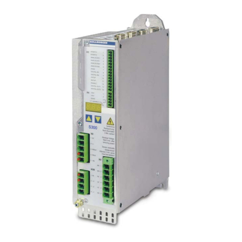
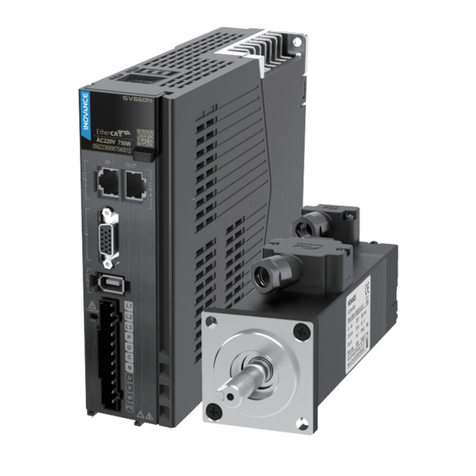
Mesa MQC Series User manual

PWM SERVO
CONTROLLERS
SERIES MQC
Operating Manual
Issue September 05

MESA Automation GmbH
RECEIVING AND HANDLING
Upon delivery of the equipment, inspect the shipping containers and contents for
indications of damages in curried in transit. If any of the items specified in the bill of lading
are damaged, or the quantity is incorrect, do not accept them until the freight or express
agent makes an appropriate notation on your freight bill or express receipt.
Claims for loss or damage in shipment must not be deducted from your invoice, nor
should payment be withheld pending adjustment of any such claims.
Store the equipment in a clean , dry area. It is advisable to leave the equipment in its
shipping container until ready fore use. Each amplifier is checked carefully before
shipment. However, upon receipt, the user should make sure that the amplifier
corresponds to or is properly rated in terms of rated voltage and current for the type of
motor which is to be driven. The descriptive label affixed to the amplifier specifies
electrical ratings.
Safety and application information
According to the enclosure the Amplifiers Motors and Power supplies may have live,
uninsulated or rotating parts or hot surfaces during operation.
The inadmissible removing of the required cover, in proper application, wrong installation
or operation may lead to personal or material damages.
For further information please refer to the manual.
Only qualified personal are permitted to install or operate the equipment.
IEC 364, CENELEC HD 384, DIN VDE 0100,0105,0110 and national regulations must be
observed
According to these general safety information a qualified person is someone who is
familiar with installation, assembly, commissioning and operation of the equipment. These
person must have the appropriate qualifications.
Order No.:74.01362

1 TECHNICAL SPECIFICATIONS FOR MQC ..............................................................................................2
1.1 BASIS MODELS .......................................................................................................................................3
1.2 ORDER EXAMPLE....................................................................................................................................3
2 GENERAL CONDITIONS ...........................................................................................................................3
3 BLOCK DIAGRAM......................................................................................................................................4
3.1 SUBPRINT OPT E LIMIT SWITCH ...........................................................................................................5
3.2 SUBPRINT MSM-OPT ............................................................................................................................5
4 POWER SUPPLY .......................................................................................................................................5
4.1 ELECTRONIC SUPPLY ±15 V...................................................................................................................5
4.2 POWER TRANSFORMER...........................................................................................................................5
5 SETTING UP THE AMPLIFIER ..................................................................................................................5
5.1 TACHO ADJUSTMENT: P3........................................................................................................................5
5.2 OFFSET: P1...........................................................................................................................................5
5.3 ADJUSTMENT OF THE SPEED CONTROLLER GAIN ......................................................................................6
5.4 ARMATURE CURRENT MEASUREMENT .....................................................................................................7
5.5 RMS - FUNCTION IARMS ...........................................................................................................................7
5.6 BEMF FEEDBACK SPEED CONTROL WITH I X R-COMPENSATION ..............................................................7
5.7 VARIABLE COMPONENTS .........................................................................................................................8
5.8 SPEED CONTROLLER COMPONENTS, BLOCK DIAGRAM ..............................................................................8
5.9 CURRENT CONTROL................................................................................................................................9
6 PROTECTION AND FAULT SIGNALLING ................................................................................................9
7 WIRING SUGGESTIONS............................................................................................................................9
8 FAULTFINDING AND REMEDY...............................................................................................................10
9 COMMISSIONING AND TERMINAL DESCRIPTION ..............................................................................10
9.1 FRONT CONNECTOR X 1 .......................................................................................................................10
9.2 SOLDER JUMPER ..................................................................................................................................11
9.3 TEST POINTS CONNECTOR X2...............................................................................................................11
9.4 TOP- SCREW TERMINAL – POWER INPUT ...............................................................................................11
9.5 TECHNICAL DATES - DRIVE BRAKING MODULE .......................................................................................12
9.6 ADDITIONAL DATES ..............................................................................................................................12
10 DRAWINGS ...........................................................................................................................................13
10.1 AMPLIFIER INPUT ..................................................................................................................................13
10.2 DC-POWER SUPPLY .............................................................................................................................13
10.3 COMPONENTS LOCATION ......................................................................................................................14
10.4 MECHANICAL STYLE..............................................................................................................................15

MESA Automation GmbH
MQC 05 V 3 EM2
1 Technical specifications for MQC
Power stage
Input voltage Chapter 1.1 Basis models
Over voltage protection 85 VDC (UA=60 V)
160 VDC (UA=120 V), 190 VDC (UA=150 V)
Chopper frequency 8 kHz (to GND)
Form factor at nominal ratings 1.01 (Rated current)
Power stage protection short circuit
Fault signalling red LED ϑmax , - Îmax ;- Umax
Braking module page 12/10.4
Speed controller
Input command Differential ± 10 V Ri = 20 kΩ
Tacho reference signal Differential ± 5V ... ± 60 V Ri = 54 kΩ
Compensation network PI (D)
correction with potentiometer or components
Speed control range 1:20000
static Error 30...3000 rpm ± 0,1 %
1...30 rpm ± 2,0 %
< 1 rpm ± 5,0 %
Current controller
Band width 1 kHz
Compensation network Pl
Current limitation 1 IArms
Current limitation 2 max. output current IAmax
Enable X1/PIN5 connect to 0 V, (optional + 24 V)
signals
Drive healthy (relay contact) X1/PIN6 connect to X1/PIN7
Contact ratings 160 VDC/20 mA
"OK“ LED green on
"error" LED red on
„Braking“ LED red + green on
other Data
Operating temperature ϑu0...45 °C derating 2 %/ K from 45 °C to 60 °C
Storage temperature -10...+70°C,
Cooling by air convection, or fan
rel. humidity 65 %, without condensation
Protection class IP 20
Isolation group C /VDE 0110
Size Chapter 9.5

MESA Automation GmbH
MQC 05 V 3 EM 3
1.1 Basis models
TYPE UAImax INRMS UCCN UNUmin 1) Umax 1)
(V) (A) (A) (V DC) (V AC) (V AC) (V AC)
MQC 0506 48 12 6 55 24 -48 V DC 16 V DC 65 V DC
MQC 0510 48 20 10 55 24 -48 V DC 16 V DC 65 V DC
MQC 0606 60 12 6 65 46 20 51
MQC 0608 60 16 8 65 46 30 51
MQC 0610 60 20 10 65 46 30 51
MQC 1206 120 12 6 125 90 30 98
MQC 1208 120 16 8 125 90 30 98
MQC 1210 120 20 10 125 90 30 98
MQC 1510 150 20 10 155 113 30 125
MQC 1515 150 30 15 155 113 30 125
UA: Output voltage UCCN ; Imax : max. Output current ; INrms : rated current 1) max. rating!
1.2 Order example
A) Standard without option MQC 1208 (M 99)
Mesanor Compact-DC-Drive Modification
Rated current INrms 8A
Output voltage UA= 120 V
B) Limit switch OPT.E and 0 V Logic (Enable and Opt.)
MQC 0606 OPT. E (-)
2 General conditions
The MQC servo modules are extremely compact PWM servo amplifiers that provide 4 quadrant speed
control of any DC servo motors with Tacho or with BEMF feedback. MQC amplifiers are conceived for
regulation of brush DC motors. The MQC is equipped with an internal power supply. From dc voltage the
amplifier is producing the current for the motor. Output current is PWM controlled and due to high chopper
frequency a large bandwidth and dynamic are granted.
Relations for the operation of the motor:
•torque is proportional to output current
•speed is proportional to output voltage
•direction of rotation corresponds to sense of the output voltage
For limit values, please look the specifications. Inadmissible working conditions or wrong application of the
amplifiers should be avoided.
Never plug in or unplug any connectors on the amplifier when power is applied. A time of discharge
of 3 minutes must be considered
The Mesanor-Amplifiers series MQC are designed for stand alone application :
Mounting: Front connector upright
Cooling: natural cooling or forced cooling (Chap.1.1)
ambient temperature less then 45°C .
Electronic supply: Internal DC/DC converter ± 15 V, max external charge with 20 mA
Supply from net: Isolation transformer required
Attention !
The MQC 05 XX Version are for 24 /48 V DC Battery supply . The input terminals L1’,L2’L3’ are used for DC
input with or without Reverse-diode.

MESA Automation GmbH
MQC 05 V 3 EM4
3 Block diagram

MESA Automation GmbH
MQC 05 V 3 EM 5
3.1 Subprint OPT E Limit switch
By connection of GND (OPT E -) or 24 V signal (OPT E +) to the terminals for negative and positive direction
the limit switch can be deactivated. If the limit switch is active, the motor will stop in these direction. The limit
switch logic level (OPT E += positive, OPT E (-)= negative logic) is set by factory. R 111 must be removed,
otherwise option B;C and E will not work.
3.2 Subprint MSM-OPT
Other Options are available by using MSM-OPT Subprint- please ask for more information.
- external current limiting, positive and negative Output current separate (Opt.A)
- Speed controlled current limiting (Opt. L) - programmable Limit-Switch (Opt. KE)
- Ramp generator (Opt. B ) - Limit switch (Opt. C) only available with negative logic
4 POWER SUPPLY
4.1 Electronic supply
±
±±
±
15 V
Electronic (+/-15V) of the amplifier is supplied from power voltage.
4.2 Power transformer
Transformers with galvanic separated primary an secondary winding are used for adjustment of supply
voltage to the existing net. The Transformers have to correspond to VDE 0550. One and three phase
transformers can be used.
If the transformer used has a star point in its secondary winding then this should be isolated and NOT
connected to earth.
A three phase transformer is recommended for current higher than 10 A continuos overall.
The factory or your dealer should be consulted to specify the proper size and secondary voltage.
5 Setting up the amplifier
The adjustment of Tacho, output current, Irms is made by factory. An adjustment of an amplifier for another
motor is possible
In order to achieve best performance for the system motor/amplifier, optimisation of speed circuit is
necessary. The following components are used:
•P 2 /R21: P- Gain
•C2: I - Gain
•P3/R31: tachometer signal
•
5.1 Tacho adjustment: P3
As a general rule, amplifiers driving servo motors are designed such that the continuously rated speed of the
motor corresponds to an input command to the amplifier of 10 V.
•apply a 10 V signal to the command input and measure the motor speed. The Tacho pot. P3 can now be
adjusted until the correct maximum speed is reached. If unable to obtain the speed over range of P3, then
consult factory for modifications.
Standard-range:
Left side: 5 V Tacho input voltage correspond to 10 V Set value
Right side: 60 V Tacho input voltage correspond to 10 V Set value
adjustment of the standard range with R31
Components can be adjusted in factory or by service.
5.2 Offset: P1
If an input of exactly 0 V is applied to the command input then the motor shaft should be stationary. Any
creep may be eliminated with P 1.

MESA Automation GmbH
MQC 05 V 3 EM6
5.3 Adjustment of the speed controller gain
Amplifiers are equipped with a standard optimisation and can be adapted by P2. Is this adjustment not
possible, PI on the Personality card must be checked.
P-Gain: P2
Standard range: Right side: 160
Left side: 8
adjustment of the standard range with R21
A) Response when correctly adjusted
Demand Signal
t1; t3 acceleration
IDC
IAMotor current t2; t4 deceleration
UTSpeed OPTIMAL
(Tacho)
Incorrect Response
IDC Motor current Attention!
IAmismatched
Motor current oscillates
UTSpeed P-Gain too high
(Tacho) adjust with P2
t1 t2 t3 t4

MESA Automation GmbH
MQC 05 V 3 EM 7
5.4 Armature Current Measurement
Armature current is measured by means of a shunt placed in series with the armature circuit. The voltage
produced can be measured at the „I Monitor“ test point. 10 Volts output corresponds to the maximum current
of the amplifier.
Max. Output current IAmax: P4
The amplifier is capable of supplying twice is rated current for 1.5-5 seconds. Peak current will be adjusted by
P4.
Standard-Range: Right side: IAmax = 1 x Imax = Type-max. current
Left side: IAmax = 0,03 x I max
Current balance: P7
Adjustment of the internal Current measurement! Set by factory, do not change !
5.5 RMS - Function IArms
Momentary current is processed into an I rms. Value by a squarer network and is negatively feed back to the
armature current control point via a threshold value switch. The I rms. Current is adjusted with P5 and is
maintained irrespective of the curve shape of the armature current actual value.
I
IAmax t1= acceleration pick-up
IArms t2= limitation
τ= t2-t1(without pre charge)
t1t2t
RMS output current IArms: P5
Follow the procedure given above for adjustment of IAmax. The IArms pot P 5 can be adjusted and is value read
from the monitor after about 5 seconds.
Standard-
Range Right side: IArms = 1 x INrms = Type rated current
Left side: IArms = 0,1 x INrms
5.6 BEMF feedback Speed control with I x R-compensation
Application without Tacho feedback are possible with lower accuracy of the speed controller
the use of an compensation resistor R12 gives an increase of accuracy.
Attention:
Solder jumper Br1, Br2 close for BEMF operation, in this case BR 3 must be open !
For amplifiers with more then 60 V output voltage never close direct BR1 + Br2 use two additional resistors
RV (R211/212)

MESA Automation GmbH
MQC 05 V 3 EM8
5.7 Variable components
Set value adjustment: R111 Standard: 10 k Ω
Tacho adjustment: R31 Standard: 1,8 kΩ
IxR compensation: R12 Standard: not used
5.8 Speed controller components, Block diagram
lntegral part C2 Standard: C2 = 0,1 µF Proportional part P2 / R 21 Standard: R21 = 82 kΩ
TN = R21 x C2
KNS = R21/R111 x K (command gain)
KN = R21/(P3 + R31) x K (error gain)
K factor is the result of P2 adjustment : Right side: K = 20
Left side: K = 1
Block diagram Speed control

MESA Automation GmbH
MQC 05 V 3 EM 9
5.9 Current control
The controller is optimised by factory, do not change !
6 Protection and fault signalling
The green LED indicates the proper function of the unit. In case of a fault, a signal is given by the front red
LED (H1), power stage will be disable and the „ready/drive healthy" relay contact will be open.
Reset the amplifier: supply voltage off-/-on
Monitoring ground fault
Over currents due to ground fault causes the safety switching circuit to respond the same way as an over
current fault.
Monitoring over voltage
If over voltage occurs in the DC Bus voltage, a fault is signalled.
Monitoring under voltage
The +/- 15 V will drop to 0V DC and disables the amplifier.
Monitoring over temperature of the power stage
Monitoring of the heat sink temperature up to 90 °C or 190 °F
7 Wiring suggestions
•It is important that the amplifier (Rack or stand-alone) is properly earthed. If the amplifier is not earthed
then if an earth fault occurs in the motor circuit the output of the amplifier will be destroyed.
•Each motor must be wired separately (cable should be shielded)
•Motor cable may be shielded if there is a requirement for reduced electrical noise.
•Speed demand and tacho circuits should be individually shielded (twisted) pairs.
•Speed demand inputs are differential inputs consequently either polarity can be used. It is Important that if
a single ended input is used then one of the amplifier inputs must be connected to ground. The controller
and the amplifier must operate with the same GND reference potential.
•All control inputs (for example: limit switch, speed demand) have to be twisted and shielded pairs.
•If cables with two outside shields (better EMV security) are used, the outside shield must be connected to
earth on both sides, the inside shield must be connected to the rack. GND contacts of amplifiers are not
suited to be connected with the shield circuit.

MESA Automation GmbH
MQC 05 V 3 EM10
8 Faultfinding and remedy
Fault Cause Remedy
The motor will not start supply voltage missing check all fuses are good and supply voltage are
present
there is no current drive not enable Terminal X1/Pin5 should be connected to 0VDC
(optional +24V) for power stage enable
Motor wiring open check the wiring for the armature circuit
The motor runs at an uncontrollably high
speed after switching on.
The control circuit is polarised Change the polarity of the tachometer or the
motor.
The motor will not start although current
is present
The motor is blocked (mechanically)
Shorted motor circuit
Release the brake, if there is one; if necessary
dismantle the motor and run no-load test.
Check the wiring of the armature circuit
The motor runs unevenly P-portion too high
I-portion too small
Turn P2 counter clockwise
Increase C8
Wiring fault at control leads or tachometer
leads
Check the shielding and check wiring
After enable the amplifier Choke are not wired in the armature check wiring
the red fault LED is lit choke and/or motor inductance too low the value must amount to, at least, the value for
the corresponding amplifier
short circuit in the motor, wiring or chokes check wiring, motor and chokes
After turn on amplifier the red LED is lit
without enable amplifier
power stage is defective exchange amplifier
the red LED is on after a long running
time
power stage overheat let the module cool down
Red LED goes on when the motor is
decelerating
over voltage caused by high system inertia A braking regulator board needs to be added to
insure proper amplifier use
Red LED goes on immediately after
power up
Over voltage caused by high bus voltage check transformer and net
9 Commissioning and terminal description
9.1 Front connector X 1
PIN Signal direction Function Remark
1
2
- IN
+ IN
Set value differential , Ri = 20 KΩ, max. input voltage
20 V ,max. input Voltage to GND +/- 30 V
3
4
+ IN
- IN
Tacho input differential, Ri = 54 KΩ, max. input voltage
65 V , max. input voltage to GND +/- 70 V
Att. BEMF control for output voltage higher then 60V
5 IN Enable negative Logic: open Drive disable
0V (GND) Drive enable
Attention! do not connect to source
positive Logic: open or 0V(GND) Drive disable
+ 24 V Drive enable
6
7
OUT
OUT
drive healthy
signal
relay contact
closed if Drive OK
8OUT
(IN)
+ 15 V
(Limit switch)
Auxiliary Voltage max. load with 20 mA, not available if using OPT E
input for OPT E Limit switch Logic level set by factory
90V
E(GND) Electronic ground
10 OUT
(IN)
- 15 V
(Limit switch)
see PIN 8
11
12
+ OUT
- OUT
Motor A1
Motor A2
notice diameter , never short to ground or A2 or power input
ATTENTION ! Apply no Voltage
13
14
IN
IN
+ Ucc
- Ucc/

MESA Automation GmbH
MQC 05 V 3 EM 11
9.2 Solder jumper
Solder jumper Function (closed) Remark
BR 1 Drive output to Tacho input BEMF control
BR 2 Drive output to Tacho input BEMF control
BR 3 Tacho input to GND disturbance reduction
BR 4 P-connector R= 1,8 KΩ
BR 5 Enable logic level + 24 V set by factory
9.3 Test points connector X2
Test point X2 /PIN Remark
2 Speed controller output/ current command
3 Tacho signal
4 current monitor +/- 10V = Imax
6 current command (Pot. P4)
10 Speed control junction
12 -15 V
14 0VE (GND)
18 Speed command
19 +15 V
20 Enable CMOS level 15 V
21 Error over voltage 0 = Error
22 Error over current 1 = OK
23 Error over temperature
24 Error input from Option subprint
Attention ! All test points refer to 0VE/GND power and logic ground direct connected
9.4 Top- Screw terminal – power input
Type PIN 1 PIN 2 PIN 3 PIN 4 Supply
MQC 0506 Housing / GND -Ucc + Ucc direct + Ucc via reverse diode DC
MQC 0510 Housing / GND -Ucc + Ucc direct + Ucc via reverse diode DC
MQC 0606 Housing / GND L'3 (AC) L'2 (AC) L'1 (AC) AC
MQC 0610 Housing / GND L'3 (AC) L'2 (AC) L'1 (AC) AC
MQC 1206 Housing / GND L'3 (AC) L'2 (AC) L'1 (AC) AC
MQC 1208 Housing / GND L'3 (AC) L'2 (AC) L'1 (AC) AC
MQC 1210 Housing / GND L'3 (AC) L'2 (AC) L'1 (AC) AC
MQC 1510 Housing / GND L'3 (AC) L'2 (AC) L'1 (AC) AC
MQC 1515 Housing / GND L'3 (AC) L'2 (AC) L'1 (AC) AC

MESA Automation GmbH
MQC 05 V 3 EM12
9.5 Technical Dates - Drive Braking module
Type UBR ON (V DC) UBR OFF (V DC) PMAX (W) Pcont. (W)
MQC 0506 77 74 530 10
MQC 0510 77 74 530 10
MQC 0606 77 74 530 10
MQC 0610 77 74 530 10
MQC 1206 140 137 1800 10
MQC 1208 140 137 1800 10
MQC 1210 140 137 1800 10
MQC 1510 180 175 2200 10
MQC 1515 180 175 2200 10
Attention : Never overload the braking system, calculate before the max. power.
9.6 Additional Dates
Type Fuse F2
(A)
internal choke
(mH)
Lmin FAN Size
(mm)
Min. distance
(mm)
Wight
(Kg)
RVin KΩ
ΩΩ
Ω
0,25 W/1% (R211/212)
MQC 0506 6,3 1,1 50 80/30 1,3 .........
MQC 0510 10 0,5 50 80/30 1,3 .........
MQC 0606 6,3 1,1 1 50 30 1,3 -
MQC 0608 8 0,5 0,5 50 30 1,3 -
MQC 0610 10 0,5 0,5 50 30 1,3 -
MQC 1206 6,3 1,1 1 50 30 1,3 64,9
MQC 1208 8 1,1 1 50 30 1,3 64,9
MQC 1210 10 0,5 0,5 75 30 1,7 64,9
MQC 1510 10 0,5 0,5 75 50 1,7 100
MQC 1515 16 no 0,5 yes 75 50 1,9 100
Lmin : minimum Inductance
Please note all necessary information and drive adjustments for service and order.

MESA Automation GmbH
MQC 05 V 3 EM 13
10 Drawings
10.1 Amplifier input
10.2 DC-Power supply
Attention ! Do not ground the secondary winding !
MQC 05 XX L1’;L2’;L2’ DC Input !

MESA Automation GmbH
MQC 05 V 3 EM14
10.3 Components location

MESA Automation GmbH
MQC 05 V 3 EM 15
10.4 Mechanical style

MESA Automation GmbH
MQC 05 V 3 EM16
The manual is subject to modifications or misprint.
Please call our service for further technical questions.

MESA Automation GmbH
MQC 05 V 3 EM 17
This manual suits for next models
10
Table of contents

