INGENIA Earth EAR-3/40-C-P User manual

INGENIA-CAT S.L.
AVILA 124
08018 BARCELONA
Earth Product Manual
Edition 2022-09-07 17:47:14
For the most up to date information visit the online manual.

1. Table of Contents
1. Table of Contents 2
2. General Information 3
2.1. Manual revision history.......................................................................................................................................... 3
2.2. Disclaimers and limitations of liability ................................................................................................................. 3
2.3. Contact ................................................................................................................................................................... 3
3. Safety Information 4
3.1. About this manual.................................................................................................................................................. 4
3.2. Warnings................................................................................................................................................................. 4
3.3. Precautions ............................................................................................................................................................ 4
4. Product Description 5
4.1. Earth part numbering ............................................................................................................................................ 5
4.2. Specifications......................................................................................................................................................... 6
4.2.1. Hardware revisions ................................................................................................................................................ 9
5. Connections and wiring 10
5.1. Pinout ................................................................................................................................................................... 10
5.2. Wiring.................................................................................................................................................................... 13
6. Dimensions 14
7. Service 16

Earth Product Manual|General Information
INGENIA |2022-09-07 17:47:14
3
2. General Information
2.1. Manual revision history
Revision Release Date Changes PDF
v1 08 Jan 2019 First draft with connection guide and
recommendations.
--
v2 01 Mar 2019 Corrections on detailed specs after
testing.
Export as pdf
2.2. Disclaimers and limitations of liability
The information contained within this document contains proprietary information belonging toINGENIA-CAT S.L..
Such information is supplied solely for the purpose of assisting users of the product in its installation.
INGENIA-CAT S.L.rejects all liability for errors or omissions in the information or the product or in other documents
mentioned in this document.
The text and graphics included in this document are for the purpose of illustration and reference only. The
specifications on which they are based are subject to change without notice.
This document may contain technical or other types of inaccuracies.The information contained within this
document is subject to change without notice and should not be construed as a commitment byINGENIA-CAT
S.L..INGENIA-CAT S.L.assumes no responsibility for any errors that may appear in this document.
Some countries do not allow the limitation or exclusion of liability for accidental or consequential damages,
meaning that the limits or exclusions stated above may not be valid in some cases.
2.3. Contact
INGENIA
C/ Avila 124, 2-B
08018 Barcelona
SPAIN
Telephone: +34 932 917 682
E-mail:[email protected]
Web site:www.ingeniamc.com

Earth Product Manual|Safety Information
INGENIA |2022-09-07 17:47:14
4
•
•
•
•
•
•
•
•
•
•
•
•
3. Safety Information
3.1. About this manual
Read carefully this chapter to raise your awareness of potential risks and hazards when working with the Earth
Servo Drive.
To ensure maximum safety in operating the Earth Servo Drive, it is essential to follow the procedures included in
this guide. This information is provided to protect users and their working area when using the Earth Servo Drive, as
well as other hardware that may be connected to it. Please read this chapter carefully before starting the
installation process.
3.2. Warnings
The following statements should be considered to avoid serious injury to those individuals performing the
procedures and/or damage to the equipment:
To prevent the formation of electric arcs, as well as dangers to personnel and electrical contacts, never
connect/disconnect the Earth Servo Drivewhile the power supply is on.
Disconnect the Earth Servo Drivefrom all power sources before proceeding with any possible wiring change.
After turning off the power and disconnecting the equipment power source, wait at least 10 seconds before
touching any parts of the controller that are electrically charged or hot.
3.3. Precautions
The following statements should be considered to avoid serious injury to those individuals performing the
procedures and/or damage to the equipment:
The Earth does not have a housing. Take due precautions to prevent ESD discharge when touching the board
or mounting it to the final system.
The Earth Servo Drivecomponents temperature may exceed 100 ºC during operation.
Some components become electrically charged during and after operation.
The power supply connected to this controller should comply with the parameters specified in this
document.
When connecting the Earth Servo Driveto an approvedpower source, do so through a line that is separate
from any possible dangerous voltages, using the necessary insulation in accordance with safety standards.
Motion control equipment can move rapidly with very high forces. Unexpected motion may occur especially
during product commissioning. Keep clear of any operational machinery and never touch them while they
are working.
Do not make any connections to any internal circuitry. Only connections to designated connectors are
allowed.
All service and maintenance must be performed by qualified personnel.
Before turning on the Earth Servo Drive, check that all safety precautions have been followed, as well as the
installation procedures.
Earth Product Manual|Product Description
INGENIA |2022-09-07 17:47:14
5
4. Product Description
The Earth Servo Driveis a compact solution designed to control servo systems based on brushless and brushed
motors. It has been designed with the objectives of high control performance, very high energy efficiency, low
standby loss, minimal size, robustness, and optimized cost. It provides fullyfeatured motion control for brushless
and brushed motors with hall sensors and encoders. Can be controlled in torque, velocity and position mode. It can
be directly wired or mounted on a base board, the connectors are conveniently placed on a 2.54 mm standard grid.
The servo drive can be easily interfaced with multiple networks: USB, RS-232 and CANopen in the field. It can also
be programmed with standalone macros for many functionalities using
It can control 100 W of continuous power and up to 180 W of peak power, Earth Servo Drivehas been designed with
efficiency in mind to minimize self-heating and standby power loss. It incorporates cutting-edge power power
budged management together with a fully rugged (against short-circuits, over-temperature, overload, over and
under-voltage) high-efficiency power stage as well as optimized control algorithms to provide the perfect trade-off
between electromagnetic emissions and performance.
4.1. Earth part numbering
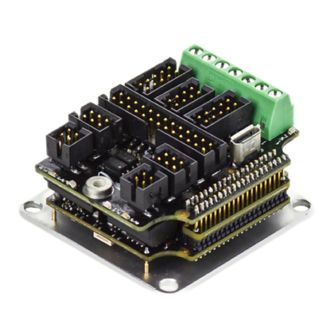
Ordering part
number
Status Image
EAR-3/40-C-P ON DEMAND

Earth Product Manual|Product Description
INGENIA |2022-09-07 17:47:14
6
4.2. Specifications
Electrical and power specifications
Part number →EAR-3/40-C-P
Power supply nominal voltage 8 VDC to 40 VDC
Transient peak voltage 44 V (1 s) 48 V (10 ms)
The drive includes a high power TVS (transient Voltage
Suppressor) that can absorb small overvoltage peaks and
clamps at 50 V.
Logic supply voltage Not needed, supplied from the power supply voltage.
5 V supply output 5 V ± 3% 350 mA max. output for feedbacks or other purposes.
Internal DC bus capacitance 23 µF
Minimum motor inductance 100 µH
Nominal phase continuous current 3 ARMS (50 ºC air temperature, no heatsink needed)
Maximum phase peak current 6 ARMS (5 s)
Current sense range ± 8.25 Apk (full range)
Accuracy is better than ± 2% between -6.5 A and 6.5A. Current
sense error can be up to ±10% outside this range.
Current sense resolution 16.11 mA/count (10 ADC bits)
Cooling Natural convection or by gap pad touching power stage
transistors in case current is needed at high temperature or no
air convection is available.
Note that soldering the drive to a daughter board with big GND
plane will improve heat dissipation through the pins.
Connectors 2 pin headers 2.54 mm pitch on 2.54 mm matrix. MicroUSB
connector.
Standby power consumption 0.5 W @ 8 V supply, 0.6 W @ 24 V, 0.9 W @ 36 V, 1 W @ 40 V
(max. without feedbacks or 5 V connected)
Efficiency >95% power stage efficiency at the rated power and current
Motion control specifications

Earth Product Manual|Product Description
INGENIA |2022-09-07 17:47:14
7
•
•
•
•
•
•
•
•
•
•
•
•
•
•
•
•
•
•
•
•
•
•
•
•
•
•
•
•
Motion control core Ingenia E-Core with EMCL2.
Supported motor types Rotary brushless (trapezoidal and sinusoidal)
Linear brushless(trapezoidal and sinusoidal)
DC brushed
Rotary voice coil
Linear voice coil
Power stage PWM frequency 20 kHz (default)
40 kHz (alternative PWM frequency, configurable). Use only for
low inductance motors to reduce current ripple. Otherwise 20
kHz provides best DC bus usage and lower EMI.
Current sensing On phases A and B and C, 10 bit ADC resolution.
Sensors for commutation (brushless motors) Digital Halls (Trapezoidal)
Quadrature Incremental encoder (Sinusoidal / Trapezoidal)
PWM encoder (Sinusoidal / Trapezoidal)
Analog potentiometer (Sinusoidal / Trapezoidal)
Sensorless FOC
Sensors supported for servo loops Digital halls
Quad. Incremental encoder
PWM encoder
Analog potentiometer
DC tachometer
Sensorless FOC
Supported target sources Network communication – USB
Network communication – CANopen
Network communication – RS-232
Standalone (execution from Internal EEPROM memory)
Analog input (0 to 5 V)
Step and Direction (Pulse and direction)
PWM command
Encoder follower / Electronic Gearing
Inputs/outputs and protections
Inputs and Outputs 2 x non isolated multi-purpose 5V inputs. GPI1/HSGPI1/AN1,
GPI2/HSGPI2/AN2. Can be used as general-purpose inputs /
high-speed inputs for PWM input /analog inputs.
1 x 3.3V logic output GPO1 (1 kΩseries resistance)
Inputs and Outputs maximum absolute
voltage
-1V ~ 6V working range. Includes ESD protection.
IEC 61000-4-2 (ESD) 15kV (air), 8kV (contact)
IEC 61000-4-4 (EFT) 40A (5/50ns)
Digital inputs Ready for CMOS and TTL. Schmitt trigger with ±400 mV
hysteresis. Noise filtered with first order low pass filter with fc
(-3 dB) at 50 kHz.

Earth Product Manual|Product Description
INGENIA |2022-09-07 17:47:14
8
•
•
•
•
•
•
•
•
•
•
•
•
•
•
•
•
•
•
•
•
•
Vth+ min = 1.6 V
Vth- max = 1.2 V
Analog inputs Range: 0V ~ 4.85 V
0 Vin →0 ADC counts, 4.85 V →4095 ADC Counts
1 kHz sampling time. ±2% Analog error, 12 bits.
Protections User configurable:
Bus over-voltage
Bus under-voltage
Over-temperature
Under-temperature
Over-current
Overload (I2t)
Short-circuit protections:
Phase-GND
Phase-DC bus
Phase-phase
Mechanical limits for homing functions.
Hall sequence / combination error.
ESD protectionsin all inputs, outputs, feedbacks and
communications.
EMI protections (noise filters) in all feedbacks and I/O.
High power transient voltage suppressor for short braking
(400 W peak TVS diode).
Motor brake Motor brake could be configured using GPO1 and an external
transistor.
Communications
USB µUSB (2.0) connector. The board can be supplied from USB for
configuration purposes but will not be able to power the motor.
Note: Although the drive can be powered from USB only for
configuration purposes, it will not be able to perform basic
functionalities.
Errors may occur when powered from USB only such as
"undervoltage", "initial current calibration out of range" or
others errors. Use this mode only to load configuration,
debugging or loading firmware.
Serial RS-232 standard, non-isolated.
Receiver specifications:
Input voltage range: ±30 V
Input threshold low min: 0.6 V
Input threshold high max: 2.4 V
Input hysteresis: 0.4 V typ
Input resistance: 3 kΩ~ 7 kΩ

Earth Product Manual|Product Description
INGENIA |2022-09-07 17:47:14
9
•
•
•
•
Transmitter specifications:
Output voltage swing: ±5 V ~ ± 7 V
CANopen Available. Non-isolated. 120 Ωtermination not included on
board.
CiA-301,CiA-305 andCiA-402 compliant.
Environmental and mechanical specifications
Ambient air temperature -40 ºC to +50 ºC full current (operating).
+50 ºC to +85 ºC current derating (operating).
-40 ºC to +125 ºC (storage).
Internal over-temperature trip 100ºC
Maximum humidity 5% - 85% (non-condensing)
Dimensions 29.3 mm x 20.3 mm x 12.8 mm. See Dimensions.
4.2.1. Hardware revisions
Hardware revision* Date Description and changes
1.0.0 March 2019 First product version.
*Version can be read on the bottom of the PCB under the USB connector.

Earth Product Manual|Connections and wiring
INGENIA |2022-09-07 17:47:14
10
5. Connections and wiring
5.1. Pinout
The Earth Servo Drive is designed to be plugged on a base board, soldered, or directly wired with cables. It is has
2.54 mm pitch pin headers on a 2.54 mm matrix so it can be easily adapted to breadboards.
The pin headers are FCI 77311-818-11LF with gold plating, 5.84 mm contact length and 0.62 mm square pins.
Pinout
Pin PCB
Text
Signal Functionality
1 L CANL CAN bus line dominant low
2 H CANH CAN bus line dominant high
3 G GND Ground for CAN bus
4 R RS232_R
X
RS232 receive data (should be connected to master TX)

Earth Product Manual|Connections and wiring
INGENIA |2022-09-07 17:47:14
11
•
•
•
•
•
•
5 T RS232_T
X
RS232 transmit data (should be connected to master RX)
6 G GND Ground for RS232
7 - GND Power supply negative (connected to circuit ground)
8 + +VBUS Power supply positive
9 A PHASE_
A
Motor phase A (Positive for DC motor)
10 B PHASE_
B
Motor phase B (Negative for DC motor)
11 C PHASE_
C
Motor phase C (Do not connect for DC motor)
12 G GND Ground for digital halls
13 3 D_HALL
3
Digital hall sensor 3 input. 5 V levels, includes a 1 kΩpullup to 5V.
14 2 D_HALL
2
Digital hall sensor 2 input. 5 V levels, includes a 1 kΩpullup to 5V.
15 1 D_HALL
1
Digital hall sensor 3 input. 5 V levels, includes a 1 kΩpullup to 5V.
16 5V 5V_OUT 5V output for feedbacks or I/Os, can provide up to 350 mA
17 A ENC_A Digital quadrature encoder A input. 5V single ended levels. Input resistance is 14.7
kΩ.
18 B ENC_B Digital quadrature encoder B input. 5V single ended levels. Input resistance is 14.7
kΩ.
19 G GND Ground for encoder or I/Os
20 i1 IN1 Input 1. 0 ~ 5 V range. Can be used as:
General purpose digital input 1.
High speed digital input 1.
Analog input 1.
21 i2 IN2 Input 2. 0 ~ 5 V range. Can be used as:
General purpose digital input 2.
High speed digital input 2.
Analog input 2.

Earth Product Manual|Connections and wiring
INGENIA |2022-09-07 17:47:14
12
•
•
•
22 o1 OUT1 Digital output 1. 3.3V levels with 1 kΩseries resistance.
Notes
For initial configuration and testing, 2.54 mm pitch jumper cables (Dupont style) can be used. This cables are
not recommended for final applications as they are not rated for the drive current and will not withstand
shock and vibration.
All the GND pins are connected to the same plane but are positioned to simplify wiring and minimize ground
loops.
The connectors can be plugged or soldered directly on a base board. A mating PCB female could be 2x Sullins
connector PPPC111LFBN-RC.

Earth Product Manual|Connections and wiring
INGENIA |2022-09-07 17:47:14
13
•
•
•
•
5.2. Wiring
Following is a recommended wiring diagram for a typical application with a brushless motor with hall sensors and
CAN + RS232 communications.
For best results follow this wiring and layout recommendations:
Ensure that the motor phases are separated from any other signals with a > 1 mm clearance. Do not put
ground planes under motor phases to minimize capacitive coupling. Motor phases are the main source of
EMI by far.
Route CAN signals as differential pairs and ensure that a 120 Ωtermination is available at both ends of the
CAN bus.
Separe power ground from digital ground.
An additional DC bus capacitor could be added to minimize ripple but it is only necessary for very small
batteries that could be overheated or for power supplied systems that do not accept regenerative braking. In
this case a capacitance around 100µF to 1000 µF may be recommended.

Earth Product Manual|Dimensions
INGENIA |2022-09-07 17:47:14
15

INGENIA-CAT S.L.
8-14 MARIE CURIE, ADVANCED
INDUSTRY PARK
08042 BARCELONA
7. Service
We are committed to quality customer service. In order to serve in the most effective way, please open a ticket on
our service desk at www.ingeniamc.com/supportor contact your local sales representative for assistance.
If you are unaware of your local sales representative, please contact the Customer Support.
France A2V www.a2v.fr a2v@a2v.fr
Norway ELECTRO DRIVES AS www.electro-drives.no
firmapost@electro-
drives.no
South Korea SERVOSTAR www.servostar.co.kr servo@servostar.co.kr
United Kingdom
MOTION CONTROL
PRODUCTS
www.motioncontrolproducts.
com
info@motioncontrolproduct
s.com
Table of contents
Other INGENIA Servo Drive manuals

INGENIA
INGENIA Jupiter JUP-20/80 User manual

INGENIA
INGENIA Everest XCR User manual

INGENIA
INGENIA Triton Go User manual

INGENIA
INGENIA Pluto User manual

INGENIA
INGENIA Everest CORE User manual

INGENIA
INGENIA Everest XCR User manual

INGENIA
INGENIA Titan GO User manual

INGENIA
INGENIA Titan GO User manual

INGENIA
INGENIA Neptune User manual

INGENIA
INGENIA Nix series User manual