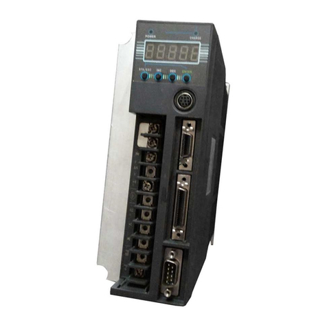
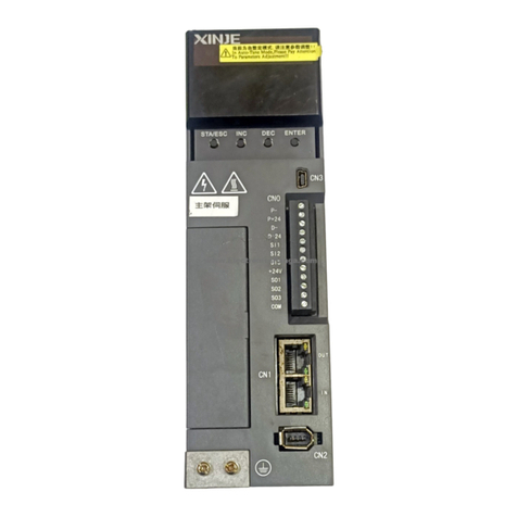
Xinje DS5B Series User manual

DS5Bseries servo drive
Fast manual
Wuxi Xinje Electric Co., Ltd.
Data No. SC503 20180511 1.0

This manual is suitable for below users
Servo system installation
Installation and wiring
Test run and servo debug
Maintenance and inspection
Responsibility statement
the contents of the manual though have been carefully checked, but mistakes is
unavoidably, we can't guarantee completely consistent
we will check the contents of the manual, and carry on the correction in future
versions, welcome to put forward valuable opinion
The contents described in the manual, if there are any changes, please understand we
will not prior notice
Contact us
If you have any questions about the use of this product, please contact the agent or xinje
company.
Tel: 0510-85134136
Fax: 0510-85111290
Add: 4 / f, building 7, creative industrial park, no. 100, ticui road, wuxi city
Code: 214072
Website: www.xinje.com
Related manual
Please contact us for the DS5B series user manual.

Catalog
►►Confirmation when receive the products ...........................................................................1
►►Safety caution ....................................................................................................................1
1.Servo system...........................................................................................................................3
1-1.Servo drive..................................................................................................................3
1-1-1.Part description ................................................................................................3
1-1-2.Model name......................................................................................................3
1-1-3.Performance .....................................................................................................4
1-2.Servo motor.................................................................................................................5
1-2-1.Part description ................................................................................................5
1-2-2.Model name......................................................................................................6
1-3.Cable ...........................................................................................................................6
1-3-1.Cable configuration..........................................................................................6
1-3-2.Model name......................................................................................................7
1-4.Other accessories.........................................................................................................8
1-4-1.Regenerative resistor........................................................................................8
2.Product installation...............................................................................................................10
2-1.Servo drive installation..............................................................................................10
2-1-1.Installation location........................................................................................10
2-1-2.Environment conditions.................................................................................10
2-1-3.Installation standard .......................................................................................10
2-2.Servo motor installation ............................................................................................12
2-2-1.Installation environment.................................................................................12
2-2-2.Environment conditions .................................................................................13
2-2-3.Installation notes ............................................................................................13
2-3.Servo motor dimension .............................................................................................17
2-4.Servo drive dimension...............................................................................................23
3.Servo drive and motor wiring...............................................................................................25

3-1.Main circuit terminals ...............................................................................................26
3-2. Control terminals......................................................................................................29
3-3. Communication port.................................................................................................33
3-4. Power–off brake(BK)..........................................................................................34
3-4-1. Wiring example.............................................................................................34
3-4-2. Brake signal...................................................................................................35
3-4-3. The switch time between BK and SON.........................................................35
3-4-4. Brake ON parameters....................................................................................36
4. Operation before using servo system...................................................................................37
4-1. Operate panel............................................................................................................37
4-1-1. Group P parameters.......................................................................................39
4-1-2. Group U parameters......................................................................................39
4-1-3. FX-XX auxiliary function.............................................................................44
4-2. Panel key operation ..................................................................................................47
4-3. Change motor code...................................................................................................48
5. DS5 series rigidity gain debug.............................................................................................49
5-1. DS5 adaptive mode ..................................................................................................49
5-1-1. Adaptive mode selection switch parameter ...................................................49
5-1-2. Recommended inertia ratio for default parameters........................................51
5-2. DS5 series auto-tuning mode....................................................................................52
5-2-1. No instruction auto-tuning ............................................................................52
5-2-2. Auto-tuning with instruction .........................................................................52
5-3 DS5 series manual adjustment mode.........................................................................53
5-3-1. Reference value of load inertia gain in manual adjustment mode .................53
5-3-2. Manual auto-tuning parameters.....................................................................53
6. Alarm information ...............................................................................................................55
7. Parameter list.......................................................................................................................64
7-1. Control parameter list...............................................................................................64

7-2. Monitoring state .......................................................................................................83
7-3. FX-XX parameters ...................................................................................................87
Appendix.................................................................................................................................88
Appendix 1 motor specification table..............................................................................88
Appendix 2 servo drive and motor matching table ..........................................................95
Appendix 3 Parameter Modbus address ..........................................................................95

►►Confirmation when receive the products
After the arrival of the product, please confirm the integrity of the product in the following
aspects.
Items
Comments
Are the delivered products the ones
that were ordered?
Check the model numbers marked on the nameplates of
the servomotor and servo drive.
The panel displays flashing “code”
Please set motor code in P0-33 (the motor code please
refer to motor label)
Does the servomotor shaft rotate
smoothly?
The servomotor shaft is normal if it can be turned
smoothly by hand. Servomotors with brakes, however,
cannot be turned manually.
Is there any damage?
Check the overall appearance, and check for damage or
scratches that may have occurred during shipping.
Are there any loose screws?
Check screws for looseness using a screwdrive.
Is the motor code the same with
the code in drive?
Check the motor code marked on the nameplates of the
servomotor and the parameter P0-33 on the servo drive.
If there is anything wrong with the items listed above, please contact the agent or xinje
company.
►►Safety caution
Confirmation when receive products
DO NOT install any driver which is damaged, lack of accessories or not the same
with the model ordered.
Installation
Cut off external power supply before installation.
Wiring
Cut off external power supply before wiring.
Connect AC power supply to the corresponding terminals.

Do not connect a three-phase power supply to the U, V, or W output terminals.
Use 2mm2wire to grounding the ground terminals.
For wiring please make sure that the encoder lines, power lines in loose state, not
tight, so as to avoid cable damage.
Product running and maintenance
Do not remove the panel cover while the power is ON.
Do not touch terminals for 10 minutes after the power has been turned OFF.
Do not connect with any motor when trial operation.
Before starting operation with a machine connected, change the settings to match
the parameters of the machine.
Do not attempt to change wiring while the power is ON.
Do not touch the heat sinks during operation.

1.Servo system
1-1.Servo drive
1-1-1.Part description
1-1-2.Model name
DS5B –2 0P7 –PTA
CN1
CN2
L
N
.
U
V
W
P
D
C
CN0: pulse, direction
I/O signal
CN1:for fieldbus function
Connect fieldbus module
CN2:encoder cable
RS232 port
Power supply
Motor wiring
Regenerative
resistor
.
.
Voltage level
2: 220V
4: 380V
Series name
DS5B: basic type
Suitable motor
capacity
0P1: 0.1KW
0P2: 0.2KW
0P4: 0.4KW
0P7: 0.75KW
1P5: 1.5KW
Configuration type:
P-input command type:
pulse
Encoder type:
T- communication encoder
A-design order: A

1-1-3.Performance
Servo unit
DS5B series 220V
Suitable encoder
17/23bit encoder
Input power supply
DS5B-2□P□-PTA: single/3-phase AC200~240V, 50/60Hz
【below 1.5KW(except 1.5KW) can use single phase
AC200~240V 50/60Hz; 1.5KW and up please use 3-phase
AC200~240V 50/60Hz. (for single phase power supply, please
connect L1, L3, otherwise it will affect the power-off memory)】
Control method
3-phase full wave rectifier IPM PWM control sine current
driving mode
Using
condition
Using
temperature
0~+50 ℃
Storage
temperature
-20~+85 ℃
Humidity
Below 90%RH (no condensation)
Resistance
to vibration
and impact
strength
4.9m/s2 / 19.6m/s2
Structure
Base installation

1-2.Servo motor
1-2-1.Part description
Encoder part
Frame
Flange
Output (transmission) shaft

1-2-2.Model name
MS5S –80 ST E –C S 02430 B Z - 2 0P7 –S01
Name Rated power
(KW)
0P2 0.2
0P4 0.4
0P7 0.75
Name Voltage level
2 220V
4 380V
Name Power-off brake
- -
Z with
Name Shaft
A No key
B With key
Name inertia
MS5S Low inertia
MS5G Middle inertia
MS5H High inertia
Name Base no.
60 60 base
80 80 base
Name Product name
ST Sine driven motor
Name Encoder type
C Magnetic
T Optical
Name Rated torque (N·m)
00630 0.637
01330 1.3
Rated speed (rpm)
3000
3000
Name Encoder precision
S Single rotate 17 bits
M Multi-rotate 17 bits
U Single rotate 23 bits
L Multi-rotate 23 bits
Name Design no.
S01 standard
02430 2.39 3000
Name Oil seal
- -
E with oil seal
1-3.Cable
1-3-1.Cable configuration
Servo drive model
Encoder cable
Motor cable
Brake cable
DS5B-20P1-PTA
DS5B-20P2-PTA
DS5B-20P4-PTA
DS5B-20P7-PTA
CP-DP-M(B)-length
CM-P07-length

DS5B-21P5-PTA
DS5B-22P3-PTA
DS5B-22P6-PTA
CP-DL-M(B)-length
CM-L15-length
CB-P03-length
CMB-W07-M-length
DS5B-43P0-PTA
DS5B-45P5-PTA
DS5B-47P5-PTA
CP-DL-M(B)-length
CM-XL60-length
1-3-2.Model name
Encoder cable model
CP –DP –M - 02
Length 02: 2m
03: 3m
M: magnetic type
B: with battery box
magnetic type
DP: amp plug
DL: aviation plug
CP: normal encoder cable
CPT: high flexible encoder cable

Power supply cable model
CM –P –07 - M - 03
Length: 02: 2m; 03: 3m
Diameter: 07: 0.7mm²; 15: 1.5mm²;
25: 2.5mm²; 60: 6mm²; 100: 10mm²
P: amp plug W: amp plug
L: small aviation plug XL: middle aviation plug
CM: normal power supply cable
CMT: high flexible power supply cable
M: magnetic type
Brake cable model
CB-P03-length (Applicable to 750W and below power motors with suffix S01).
1-4.Other accessories
1-4-1.Regenerative resistor
When the servo motor operates in generator mode, power is returned to the servo drive side.
This is called regenerative power. The regenerative power is absorbed by charging the
smoothing capacitor, but when the capacitor’s charging limit is exceeded, the regenerative
power needs to be reduced by the regenerative resistor.
The servomotor is driven in regeneration (generator) mode in the following conditions:
From decelerating to stop for acceleration/deceleration operation.
Move down on the vertical axis.
The external load drives the motor running

Servo drive model
Regenerative resistor connection terminals
DS5B-2□P□-PTA
for internal regenerative resistor: short P+ and D, disconnect P+ and
C, P0-24=0.
for external regenerative resistor: connect resistor between P+ and C,
disconnect P+ and D, P0-24=1, P0-25=power value, P0-26=resistor
value.
The below table is external regenerative resistor specifications for each motor.
Servo drive
Min resistor
(cannot smaller than
this value)
External
regenerative resistor
(recommend value)
External
regenerative resistor
(recommend power)
DS5B-20P2-PTA
≥50Ω
50Ω—100Ω
≥200W
DS5B-20P4/7-PTA
≥40Ω
40Ω—100Ω
≥500W
DS5B-21P5-PTA
DS5B-22P3/6-PTA
≥25Ω
25Ω—50Ω
≥1000W
DS5B-43P0-PTA
≥55Ω
25Ω-65Ω
≥2000W
DS5B-45P5-PTA
≥25Ω
25Ω-50Ω
≥2000W
DS5B-47P5-PTA
≥25Ω
25Ω-50Ω
≥2000W
Note:
1. The temperature will be very high when the regenerative resistor is discharging, please
using heat-resistant non-flammable wire. Don’t touch the regenerative resistor when wiring.
2. When you choose the regenerative resistor, please make the resistor value close to the min
value of recommend value. The resistor power is decided by the actual consition specially the
heat.

2.Product installation
2-1.Servo drive installation
2-1-1.Installation location
Please install in the cabinet without sunshine and rain
Please get away from corrosive and flammable gases
please do not install in high temperature, humidity, dust, metal dust environment
No vibration location
2-1-2.Environment conditions
Item
Description
Using temperature
0℃~40℃(not freeze)
Using humidity
-20%~90%RH (no condensation)
Storage
temperature
-20℃~60℃
Storage humidity
-20%~90%RH (no condensation)
Protection level
IP65
2-1-3.Installation standard
Be sure to comply with the installation standard in the control panel shown below, which is
applicable for installing multiple servo drives side-by-side in the control panel (hereinafter
called "side-by-side installation" for short).

Servo drive direction
When installing, make the front of the servo drive (the actual installation surface of the
operator) facing the operator and make it vertical to the wall. For the drive with regenerated
resistance at the bottom, please pay attention to the heat dissipation of the mounting surface to
avoid overheating of the drive and causing fire.
Cooling
As shown in the figure above, allow sufficient space around each servo drive for cooling by
cooling fans or natural convection.
Side by side installation
When install servo drives side by side as shown in the figure above, make at least 10mm
between and at least 50mm above and below each servo drive. Install cooling fans above the
servo drives to avoid excessive temperature rise and to maintain even temperature inside the
control panel.
The conditions in the control cabinet

Ambient Temperature: 0~50 ℃
Humidity: 90%RH or less
Vibration: 4.9m/s2
Condensation and Freezing: None
Ambient Temperature for Long-term Reliability: 50°C maximum
2-2.Servo motor installation
MS series servomotors can be installed either horizontally or vertically. The service life of the
servomotor can be shortened or unexpected problems might occur if it is installed incorrectly
or in an inappropriate location. Follow these installation instructions carefully.
Caution
1. The end of the motor shaft is coated with antirust. Before installing, carefully remove all
of the paint using a cloth moistened with paint thinner.
2. Avoid getting thinner on other parts of the servo motor.
2-2-1.Installation environment
Free of corrosive or explosive gases
Please choose oil seal motor in the environment with grinding fluid, oil mist, iron
powder, cutting, ect
Away from the heating source such as stove
antirust

please do not use the motor in a closed environment. Closed environment will lead to
motor temperature, shorten service life
2-2-2.Environment conditions
When used in places with water or oil, the protective effect can be achieved through the
treatment of the motor. However, when sealing the shaft through part, please specify the
motor with an oil seal. Please install the connector downward.
MS series servo motors are for indoor use, please use in the following installation conditions:
Item
Description
Using temperature
0℃~40℃(not freeze)
Using humidity
-20%~90%RH (no condensation)
Storage temperature
-20℃~60℃
Storage humidity
-20%~90%RH (no condensation)
Protection level
IP65
2-2-3.Installation notes
Item
Description
Rust proofing
◆Please clean the "anti-rust agent" at the extension end of the shaft of
the servo motor before installation, and then do the relevant anti-rust
treatment.
Through part of the shaft

Encoder notes
◆The installation process is not allowed
to impact the shaft extension, otherwise
the internal encoder will be broken.
◆When a pulley is mounted on a servo motor shaft with a keyway,
screw holes are used at the end of the shaft. To install the pulley, first
insert the double-headed nail into the screw hole of the shaft, use the
washer on the surface of the coupling end and gradually lock the nut
into the pulley.
◆For the servo motor shaft with a keyway, the shaft end screw hole is
used for installation. For a shaft without a keyway, a frictional coupling
or similar method is used.
◆When removing the pulley, a pulley stripper is used to prevent the
bearing from being strongly impacted by the load.
◆To ensure safety, a protective cover or similar device, such as a
pulley mounted on a shaft, is installed in the rotating area.

Concentricity
◆When installing the servo motor, make it meet the centering
precision requirements as shown below. If the centering is not sufficient,
vibration may occur, and sometimes the bearing and encoder may be
damaged. When installing the shaft coupler, please do not directly
impact the motor shaft, otherwise it will damage the encoder installed
on the load reverse side of shaft end.
Installation
direction
◆The servo motor can be mounted horizontally or vertically
Oil and water
solution
When using in places with drops of water, please use it on the basis of
confirming the protection level of the servo motor. Specify a servo
motor with an oil seal when there is an oil droplet that drips to the
through part of the shaft.
Using condition of motor with oil seal:
When using, please make sure the oil level is lower than the lip of the
oil seal.
Please use the motor in a condition where the oil seal keeps the spray
Measure it at 4 places of the circle, the
difference should be below 0.03mm.
Measure it at 4 places of the circle, the difference should be
below 0.03mm.
This manual suits for next models
10
Table of contents
Other Xinje Servo Drive manuals

Xinje
Xinje DS2-20P2-AS User manual

Xinje
Xinje DS5L1 Series User manual

Xinje
Xinje DF3E Series User manual

Xinje
Xinje DS3 series servo User manual

Xinje
Xinje DP-708 User manual

Xinje
Xinje DS5E Series User manual

Xinje
Xinje DS2 series User manual

Xinje
Xinje DS5K Series User manual

Xinje
Xinje DS5C Series User manual

Xinje
Xinje DS2 series User manual
Popular Servo Drive manuals by other brands

Allen-Bradley
Allen-Bradley Kinetix 5700 user manual

Rockwell Automation
Rockwell Automation Allen-Bradley Kinetix 6000 user manual

Watts
Watts CLASSIC EVO2-WK installation manual

Allen-Bradley
Allen-Bradley Kinetix 2071-AP0 installation instructions

Inovance
Inovance IS300S002-C user manual

Leadshine
Leadshine EL8-EC Series user manual