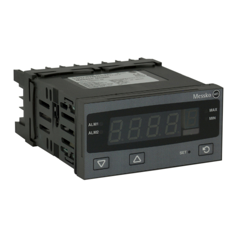
MESSKO D1272AT User manual

BA2082/02/10 ZH-EN
MESSKO®数字指示器 D1272AT
MESSKO®DIGITAL INDICATOR D1272AT
操作说明书 / Operating Instructions

BA 2082/02/102
目录
1 安全 ................................3
1.1 安全说明 ...............................3
1.2 指定应用 ...............................3
1.3 关于运行设备运转的重要提示 ..............3
2 产品规格 .............................4
2.1 操作 ..................................4
2.2 输入 ..................................5
2.3 偏移调整 ...............................5
2.4 最小/最大内存 ..........................5
2.5 报警触点 ALM1 和 ALM2(可选) .........5
2.6 模拟输出端(可选) .....................6
3 安装 ................................6
4 电气连接 .............................7
4.1 电源 ..................................7
4.2 传感器输入 .............................7
4.3 继电器输出报警 1 和报警 2(可选) ........8
4.4 模拟输出端(可选) .....................8
5 技术数据 .............................8
6 附录 ...............................10
6.1 Pt100 传感器的连接图 ..................10
6.2 有源 4-20mA 传感器的连接图 ............11
6.3 无源 4-20mA 传感器的连接图 ............11
6.4 Pt100 传感器示例 ......................12
6.5 有源 4-20mA 传感器示例 ................13
6.6 无源 4-20mA 传感器示例 ................14
Contents
1 Safety .................................3
1.1 Safety instructions. . . . . . . . . . . . . . . . . . . . . . . . . . . . . 3
1.2 Specied application........................... 3
1.3 Important notes on equipment operation .......... 3
2 Product Specication ...................... 4
2.1 Operation .................................... 4
2.2 Input ........................................ 5
2.3 Oset adjustment ............................. 5
2.4 Min-/Max-memory ............................ 5
2.5 Alarm contacts ALM1 and ALM2 (optional) ........ 5
2.6 Analog output (optional). . . . . . . . . . . . . . . . . . . . . . . . 6
3 Installation.............................. 6
4 Electrical Connection ...................... 7
4.1 Voltage supply ................................ 7
4.2 Sensor input.................................. 7
4.3 Relay outputs alarm1 and alarm2 (optional) ....... 8
4.4 Analog output (optional). . . . . . . . . . . . . . . . . . . . . . . . 8
5 Technical Data ........................... 8
6 Appendix .............................. 10
6.1 Connection diagram of Pt100 sensor............. 10
6.2 Connection diagram of active 4-20mA sensor ......11
6.3 Connection diagram of passive 4-20mA sensor .....11
6.4 Example Pt100-sensor......................... 12
6.5 Example of an active 4-20mA sensor ............ 13
6.6 Example of a passive 4-20mA sensor ............ 14
备注
此处的数据在细节上可能与所交付运行设备中的数
据有所不同。
我们保留进行更改的权利,恕不另行通知。
NOTE
Data contained herein may dier in details from the
equipment delivered.
We reserve the right to make alterations without notice.
请保留本操作说明书,以供未来参考! Please keep these operating instructions for future reference!
目录/Contents

BA 2082/02/10 3
1 安全
1.1 安全说明
参与本设备的安装、调试或运行的所有人员都必须:
- 具备相应的专业资格并
- 严格遵守本操作说明书。
违规操作或错误使用可能会导致
- 严重或致命的伤害,
- 损坏设备和用户的其他财产
- 降低设备的功能性。
本手册中的安全说明采用以下三种标识来强调重要信
息。
1.2 指定应用
D1272AT 数字指示器用于指示工艺值,例如温度或油
位。
调试装置前,务必查阅并遵守标示牌和操作说明中所指
示的操作限值。
1.3 关于运行设备运转的重要提示
用户有义务遵守国家的健康与安全法规。
特别要强调的是,在对带电部件(人接触到会发生危
险)执行工作时,只有在这些部件已断电或具有直接接
触保护的情况下,才可进行。
1 Safety
1.1 Safety instructions
All personnel involved in installation, commissioning or opera-
tion of this equipment must:
- be suitably qualied and
- strictly observe these operating instructions.
Improper operation or misuse can lead to
- serious or fatal injury,
- damage to the equipment and other property of the user
- a reduction of equipment functionality.
The safety instructions in this manual are presented in three
dierent forms to emphasize important information.
1.2 Specied application
The D1272AT digital indicator is used to indicate such process
values as temperature or oil level.
It is important to read and observe the limit values for
operation indicated on the nameplate and in the operating
instructions prior to commissioning the device.
1.3 Important notes on equipment operation
The user is obliged to comply with the national health and
safety regulations.
It is especially emphasized that works performed to live, i.e.
dangerous-contact components, are permissible only while
these components are either de-energized or protected against
direct contact.
警告
此信息表示可能会对生命与健康造成一定危险。
忽视此类警告可导致严重或致命的伤害。
小心
该信息表示可能会对本运行设备或用户的其他财产
造成一定危险。不排除造成严重或致命伤害的可
能。
备注
这些备注将给出有关特定事项的重要信息。
WARNING
This information indicates particular danger to life and
health. Disregarding such a warning can lead to serious
or fatal injury.
CAUTION
This information indicates particular danger to the equip-
ment or other property of the user. Serious or fatal injury
cannot be excluded.
NOTE
These notes give important information on a certain issue.
1 安全/Safety

BA 2082/02/104
2 产品规格
D1272AT 数字指示器使用简便,可显示标准 Pt100 或
4-20 mA 信号。
在正常运行期间,测得的值在 4 位 LCD 显示屏上显示。
2 Product Specication
The D1272AT digital indicator is an easy-to-use device for the
indication of standard Pt100 or 4-20 mA signals.
During normal operation, the measured value is shown on the
4-digit LCD display.
2.1 操作
“回车”键可用于在以下菜单之间按顺序跳跃。菜单值
约 2 秒之后显示,然后可以更改。要继续下一菜单项
目,必须使用“回车”键。
正常运行:显示测得的值(过程值)
显示最大值。要重置,按下“向上”
或“向下”键,直至显示屏上出现
4 位数。
显示最小值。要重置,按下“向上”
或“向下”键,直至显示屏上出现
4 位数。
开关点报警 1。可用“向上”或“向
下”键设置开关点。按“回车”键确
认。
开关点报警 2。可用“向上”或“向
下”键设置开关点。按“回车”键确
认。
如果报警触点激活,将在该菜单上显
示。否则,无法选择该菜单。
偏移调节可用于更改显示值。偏移值通
过“向上”或“向下”键调节,并随后
用“回车”键确认。相应地修改模拟输
出,并用校正的值激活报警触点。
最小/最大显示/Min/Max display
“回车”键/„Enter“ key
“向上”和“向下”键/
„Up“ and „down“ keys
测量单位/Unit of measure4 位显示屏/4-digit display
报警状态/Alarm status
图 1/Fig. 1
2.1 Operation
The „Enter“ key can be used to jump sequentially between the
following menus. The menu values are shown after approx.
2 seconds and then can be changed. The „Enter“ key must be
used to proceed to the next menu item.
Normal operation: Indication of the measured
value (process value)
Indication of the max. value. To reset keep
the „Up“ or „Down“ key pressed until 4-digits
appear on the display.
Indication of the Min. value. To reset keep
the „Up“ or „Down“ key pressed until 4-digits
appear on the display.
Switching point Alarm 1. The switching point
can be set with the „Up“ or „Down“ key. To
conrm press enter.
Switching point Alarm 2. The switching point
can be set with the „Up“ or „Down“ key. To
conrm press enter.
If an alarm contact is active, it is indicated in
this menu. Otherwise, this menu cannot be
selected.
The oset adjustment can be used to change
the display value by a certain value. The oset
value is adjusted by means of the „Up“ and
„Down“ keys and subsequently conrmed using the „Enter“ key.
The analog output is modied accordingly and the alarm contacts
are activated with the corrected value.
2 产品规格/Product Specication

BA 2082/02/10 5
2.2 输入
Pt100 或 4-20 mA 信号可根据设备设计(参考铭牌)与
D1272AT 的输入端连接。
监测输入范围,如果出现错误,显示以下消息:
• 输入传感器故障或者未连接。
• 输入范围降低至(下限)以下。
• 输入范围超出(上限)。
4-20 mA 输入端可与有源或无源信号结合使用。
有源信号:传感器/信号转换器已经通电,不需要任何额
外的外部电源(例如油位显示器 MTO/TT 或温度变送器
TT-PWM60)。
无源信号:传感器/信号转换器需要外部电源(例如指针
温度计MT-ST160SK/TT)。
2.3 偏移调节
偏移调节可用于更改显示值(参考章节 2.1)。相应地修
改模拟输出,并用校正的值激活报警触点。
2.4 最小/最大内存
上一次重置被存储之后,出现最小和最大测量值。可用
正面的键调用。参见章节 2.1。
2.5报警触点ALM1和ALM2(可选)
可选择为数字指示器 D1272AT 装配双继电器(参考铭
牌)。2 个常开触点的开关点可设为不同的限值,并且
可用于生成报警消息或类似信息。超出设定限值时,
特定的触点关闭(报警 1 或报警 2),并且相关状态
LED(ALM1 和 ALM2)闪烁。继电器在背面连接。参
见章节 4.3。
限值可按照章节 2.1 所述进行设置。
返回控制滞后为 1 K。
2.2 Input
A Pt100 or 4-20 mA signal can be connected to the input of
the D1272AT in accordance with the device design (refer to
nameplate).
The input range is monitored and, in case of error, the follow-
ing messages are displayed:
• The input sensor is defective or not
connected.
• The input range has fallen below (Low).
• The input range has been exceeded (High).
The 4-20 mA input can be used with an active or a passive
signal.
Active signal: The sensor/signal transducer is already powered
and does not require any additional external power source
(e.g., oil level indicator MTO/TT or temperature transmitter
TT-PWM60).
Passive signal: The sensor/signal transducer requires an
external power source (e.g., pointer thermometer
MT-ST160SK/TT).
2.3 Oset adjustment
The oset adjustment can be used to change the display value
by a certain value (refer to chapter 2.1). The analog output
is modied accordingly and the alarm contacts are activated
with the corrected value.
2.4 Min-/Max-memory
The minimum and maximum measured value occurring since
the last reset are stored. They can be called with keys on the
front. See chap. 2.1.
2.5 Alarm contacts ALM1 and ALM2 (optional)
The digital indicator D1272AT can be optionally equipped with
a double relay (refer to nameplate). The switching points of the
2 N/O contacts can be set to dierent limit values and can be
used to generate an alarm message or similar. When the set
limit value is exceeded, the particular contact closes (alarm1
or alarm2) and the related status LED (ALM1 and ALM2)
ashes. The relays are connected on the back. See chap. 4.3.
The limit values can be set as described in chap. 2.1.
The return control hysteresis is 1 K.
2 产品规格/Product Specication

BA 2082/02/106
2.6 模拟输出端(可选)
可选择为 D1272AT 数字指示器装配模拟输出端,以供
远程传输下列过程值。
• 4 - 20 mA
• 0 - 20 mA
• 0 - 5 V
• 0 - 10 V
如有要求,可通过信号转换器提供其他输出信号。
3 安装
2.6 Analog output (optional)
The D1272AT digital indicator can be optionally equipped with
an analog output for the remote transmission of the process
value as shown below.
• 4 - 20 mA
• 0 - 20 mA
• 0 - 5 V
• 0 - 10V
Upon request other output signals can be provided by means
of a signal converter.
3 Installation
小心
必须严格满足本安装手册中的安装条件要求。
CAUTION
The installation conditions demanded by this operating
manual must be strictly complied with.
D1272AT 数字指示器可安装在壁厚达 6 mm 的控制板
内。有关控制板切断尺寸,请参见图 2。
The D1272AT digital indicator can be installed in control
panels with a wall thickness of up to 6 mm. For the dimensions
of the control panel cutout, see gure 2.
按照下列要求继续安装设备:
• 将 D1272AT 数字指示器滑入控制板的切口中,确保
指示器的最终位置在正面。然后轻轻地将其按到控制板
上。检查确保控制板密封件定位正确。
• 从尾部开始,将支架框滑到设备上,直至其接触控
制板的背面。然后支架框顶部和底部的支架齿扣入设备
的支架格内。支架框的弹簧必须牢固地按到控制板的背
面。
设备安装之后便可进行连接。
Proceed as follows to install the device:
• Slide the D1272AT digital indicator into the control panel
cutout so that the nal location of the indicator is in front.
Then lightly press it against the control panel. Check to make
sure that the control panel seal is positioned correctly.
• Starting from the back, slide the holder frame over the
device until it touches the back of the control panel. The
holder teeth on the top and bottom of the holder frame will
then snap into the holder grid of the device. The springs of the
holder frame must be pressed rmly against the back of the
control panel.
After the device has been installed, it can be connected.
控制板开孔/
Control panel cutout
控制板/Control panel
控制板密封/
Control panel sealing
操作者前方/
Operator front
图 2/Fig. 2
3 安装/Installation

BA 2082/02/10 7
4 电气连接
连接 D1272AT 数字指示器时,建议使用开放的电缆终
端夹进行 M3 螺纹连接。参照附录中的连接图执行。
4.1电源
通过连接端 13
和 14 进行连接。电压:100 – 240 V AC ± 10 %,
50/60 Hz;最大 7.5 VA。
4.2传感器输入
连接输入端信号时,确保设备的测量范围符合电路的最
大负荷。
Pt100:
Pt100 输入端设计用于通过三线技术连接 Pt100 传感
器。通过端子 1 和 2 进行连接。均压线与端子 3 连接。
如果要连接 2 线传感器,端子 2 和 3 必须短路。参见
图 3。
4-20mA,有源传感器:
要连接的 4-20 mA 传感器是有源传感器时(即,不需要
其他电源电压),将传感器与端子 1 (-) 和端子 4 (+) 连
接。参见图 4。
4-20mA,无源传感器:
D1272AT 数字指示器装有为传感器/信号转换器供电
的模块。无源传感器(例如指针温度计 MT-ST160SK/
TT)可用此供电。
端子 10 (-) 和端子 12 (+) 有约 24 VDC 的传感器电源
可用。
连接传感器时,电压必须连接。为此,跨接端子 1 和
10,并将输入传感器与端子 4 (-) 和 12 (+) 连接。参
见图 5。
4 Electrical Connection
For the connection of the D1272AT digital indicator, we
recommend using open cable lugs for M3 screw-type connec-
tions. Follow the connection diagrams in the appendix.
4.1 Voltage supply
The connection is performed via the connection terminals 13
and 14. Voltage: 100– 240 V AC ±10 %, 50/60 Hz; max. 7.5 VA.
4.2 Sensor input
When connecting the input signal, make sure that the measu-
ring ranges of the devices conform to the maximum load of
the circuit.
Pt100:
The Pt100 input is designed for connection of a Pt100 sensor
by means of a 3-wire technology. The connection is made
via the terminals 1 and 2. The equalizing line is connected to
terminal 3. If a 2-wire sensor is to be connected, terminals 2
and 3 must be short-circuited. See gure 3.
4-20 mA, active sensor:
When the 4-20 mA sensor to be connected is active (i.e., no
further supply voltage is needed), connect the sensor to termi-
nal 1 (-) and terminal 4 (+). See gure 4.
4-20 mA, passive sensor:
The D1272AT digital indicator is equipped with a module for
powering a sensor/signal transducer. A passive sensor (e.g.,
pointer thermometer MT-ST160SK/TT) can be powered with
this.
The sensor power of approx. 24 VDC is available on terminal 10
(-) and terminal 12 (+).
The voltage must be looped in when the sensor is connected.
For this, jumper terminals 1 and 10 and connect the input
sensor to terminals 4 (-) and 12 (+). See gure 5.
小心
电气连接只能由合格且经过培训的人员执行,该人
员应事先查看相关国家/地区适用的安全法规。
CAUTION
The electrical connection may only be performed by qua-
lied, trained personnel who have been instructed in the
applicable safety regulations of the particular country.
4 电气连接/Electrical Connection

BA 2082/02/108
4.3 继电器输出报警1和报警2(可选)
继电器输出被设计为双继电器(即两个常开触点通过端
子 23 具有相同电势)。
将继电器连接到端子 22 和 23 或连接到 24 和 23,依
具体应用而定。
4.4 模拟输出端(可选)
模拟输出端连接至端子 21 (+) 和 19 (-)。
确保连接的设备的测量范围相同,并且遵守容许的电路
负荷。
5 技术数据
一般数据:
尺寸: 深度:110 mm,用户面板:
96 mm x 48 mm (1/8 DIN)
安装: 面板安装有锁紧机制、控制板切口
92 mm x 45 mm
端子: 螺旋式端子用于电缆接线端 M3
重量: 最大 0.25 kg
防护等级: 正面 IP 66
背面 IP 20
(面板安装后)
绝缘电压: 500 VDC,所有输入端和输出端均
进行电流隔离
操作条件:
环境温度: 0 °C - +55 °C(操作)
-20 °C - +80 °C(储存)
相对湿度: 20 % - 95 %
显示范围: 例如 0.0 °C – 160.0 °C
(参考铭牌)
分辨率: 0.1°C
准确度: < 显示范围 ± 0.25 % ± 1 位
(20 °C、60-70 % 相对湿度)
(测量范围为 160°C 时 <
±0.5 °C)
4.3 Relay outputs alarm1 and alarm2 (optional)
The relay outputs are designed as double relay (i.e., the two
N/O contacts have a common potential on terminal 23).
Connect the relay to terminals 22 and 23 or 24 and 23 depen-
ding on the application.
4.4 Analog output (optional)
The analog output is connected to terminal 21 (+) and 19 (-).
Make sure that the measuring range of the connected devices
is the same and the permissible load of the circuit is adhered
to.
5 Technical Data
General data:
Dimensions: depth: 110mm, user panel:
96 mm x 48 mm (1/8 DIN)
Installation: panel mounting with lock mechanism,
control panel cutout 92 mm x 45 mm
Terminals: screw terminals for cable lugs M3
Weight: 0.25 kg max.
Degree of protection: IP 66 at the front
IP 20 at the back
(after panel mounting)
Insulation voltage: 500 VDC, all inputs and outputs are
galvanic isolated
Operating conditons:
Ambient temp. 0 °C - +55 °C (operation)
-20 °C - +80 °C (storage)
Relative humidity: 20 % - 95 %
Display range: e.g. 0.0 °C – 160.0 °C
(refer to nameplate)
Resolution: 0.1°C
Accuracy: <±0.25 % of the display range ±1 digit
(at 20 °C, 60-70% RH)
(<±0.5°C at a measuring range of 160°C)
小心
本操作说明书中的信息适用于标准设备。使用专用
设备时,请遵守铭牌和订单上的信息。
CAUTION
The information in these operating instructions applies to
standard devices. When special devices are used, adhere
to the information on the nameplate and the order.
5 技术数据/Technical Data

BA 2082/02/10 9
环境温度的影响: 环境温度每更改 1 °C,
显示范围±0.01 %
相对湿度的影响: 可忽略
电源电压的影响: 可忽略
电源电压:
电压范围: 100–240 V AC ± 10 %,50/60 Hz
功率消耗: 最大 5VA
传感器输入概述:
绝缘: 所有输入端电流隔离达 250 V AC
取样速率: 每秒 4 次
输入端滤波器: 2.0 秒
输入端分辨率: 14 位,至少比显示屏的分辨率高 4
倍
实际值偏移: 可通过用户面板调节,± 显示范围
传感器故障: 2 秒内发出错误消息,断开输出端
传感器输入Pt100:
测量电阻: Pt100 根据 IEC751,3 线技术
输入范围: -128.8 °C 至 +526.9 °C
电线电阻: 每根导线最大 50 欧
50 欧电线电阻
时影响小于显
示范围的 0.5 %: 电线电阻
补偿: 自动
测量电流: 约 150 μA
传感器输入4-20mA:
输入范围: -20 °C - +140 °C,0 °C -
+160 °C,其他要求的值
输入电阻: 4.7 欧
变送器电源(可选):
输入: 20-28 V DC(24 V DC 标称)
负载: 最小
910
欧
(20 V DC
时为
22 mA)
双继电器(可选):
触点类型: 2 个常开开关,共用中心连接
触头负载: 在 240 VDC 时最大 2 A 电阻负载
开关功能: 数值不断增加,自动复位
滞后: 1 K
Inuence of ±0.01% of the display range per °C of
ambient temp.: the change of ambient temperature
Inuence of
relative humidity: negligible
Inuence of the
supply voltage: negligible
Supply voltage:
Voltage range: 100–240 V AC ±10 %, 50/60 Hz
Power consumption: 5 VA max.
Sensor inputs general:
Insulation: galvanic isolation of all inputs up to
250 V AC
Sample rate: 4 samples per second
Input lter: 2.0 seconds
Input resolution: 14 bit, at least 4x better than the
resolution of the dislay
Actual value oset: adjustable via user panel, ±display
range
Sensor malfunction: Error message within 2 seconds,
outputs are disconnected
Sensor input Pt100:
Measur. resistance: Pt100 acc. to IEC751, 3-wire technology
Input range: -128.8 °C to +526.9 °C
Wire resistance: 50 Ohm max. per conductor
Inuence of < 0.5 % of the display range at 50 Ohm
wire resistance: wire resistance
Compensation: automatic
Measurment current: approx. 150 μA
Sensor input 4-20 mA:
Input range: -20 °C - +140 °C, 0°C - +160 °C,
other on request
Input resistance: 4.7 Ohm
Transmitter supply (optional):
Input: 20-28 V DC (24 V DC nominal)
Load: 910 Ohm min. (22 mA at 20 VDC)
Double relay (optional):
Contact type: 2x NO switch with common throw
Contact load: max. 2 A ohmic load at 240 VAC
Switching function: at increasing values, self-resetting
Hysteresis: 1 K

BA 2082/02/1010
ܕઊٯڐ
Alarm 2, NO*
ܕઊٯڐ*
Alarm 1, NO*
13
L
+
N
--+
100 –240 VACࠥܧ૿ӟঀ*
Analog output*
Օଣԅ
* optional feature
Pt100ࢽஊ/Pt100 (RTD)
14 15 16 17 18 19 20 21
22
23
24
12
3
4
5
6
7
89
10
11
12
图 3/Fig. 3
6 附录/Appendix
使用寿命: 在标称负荷下
,> 500,000
周期运行
最小开关电流: > 20 mA
模拟输出端:
直流电压信号: 0-10 V 或 0-5 V,
负荷 1000 欧(最小值)
直流电流信号: 4-20 mA 或 0-20 mA,
负荷 500 欧(最大值)
输出范围: 与显示范围一致
残余波纹: 最大 10 %
测试:
EMC 发射
干扰: EN 50081-2(工业领域)
EMC 抗干扰力: EN 50082-2(工业领域)
防护等级: IP65,根据 IEC 60529
(仅针对正面板)
保护类: I I,与 IEC 61010-1 视同
认证: CE、UL、ULC
6 附录
6.1 Pt100传感器的连接图
Service life: > 500,000 cycles of operation at nominal load
Min. switch current: > 20mA
Analog output:
DC-voltage signal: 0-10 V resp. 0-5 V,
Load 1000 Ohm min.
DC-current signal: 4-20mA resp. 0-20 mA,
Load 500 Ohm max.
Output range: corresponding to display range
Residual ripple: 10% max.
Tests:
EMC-emitted
interference: EN 50081-2 (Industrial sector)
EMC-interference
resistance: EN 50082-2 (Industrial sector)
Degree of protection: IP65 acc. to IEC 60529 (only for front-
panel)
Protection class: II, equivalent to IEC 61010-1
Approvals: CE, UL, ULC
6 Appendix
6.1 Connection diagram of Pt100 Sensor

BA 2082/02/10 11
6.2 有源4-20mA传感器的连接图 6.2 Connection diagram of active 4-20mA sensor
6.3 Connection diagram of passive 4-20mA sensor
6.3 无源4-20mA传感器的连接图
L
+
N
--+
100 – 240 VACࠥܧ૿ӟঀ
Analog output*
-
+
߄࢛ӱS'Ғ՚૿ҵ
Input for active 4 to 20 mA signal
Ѯ࢛۟֘<*)߂םS'
Sensor power supply appr. 24
V DC/max. 22 mA
+
-
13 14 15 16 17 18 19 20 21
22
23
24
12
3
4
56
7
89
10
11
12
Օଣԅ
* optional feature
ܕઊٯڐ
Alarm 2, NO*
ܕઊٯڐ*
Alarm 1, NO*
L
+
N
--+
100 –240VACࠥܧ૿ӟঀ
Analog output*
-
+
ޗ࢛ӱS'Ғ՚૿ҵ
Input for passive 4 to 20 mA signal
Ѯ࢛۟֘<*)߂םS'
Sensor power supply appr. 24
V DC/max. 22 mA
+
-
13 14 15 16 17 18 19 20 21
22
23
24
12
3
4
5
6
7
89
10
11
12
Օଣԅ
UVZOUTGRLKGZ[XK
ܕઊٯڐ
Alarm 2, NO*
ܕઊٯڐ*
Alarm 1, NO*
图 4/Fig. 4
图 5/Fig. 5
6 附录/Appendix

BA 2082/02/1012
6 附录/Appendix
6.4 Pt100传感器示例
Pt100 זՠѮ۟֘ / Combiwell ZT-F2
23
13 14 15 16 17 18 19 20 21
9
10
11
12
87654321
24
23
22
L
+
N
--+
100 – 240 VACࠥܧ૿ӟঀ*
Analog output*
123
1
* Օଣԅ
* optional feature
ܕઊ 2ٯڐ*
Alarm 2, NO*
ܕઊ 1ٯڐ*
Alarm 1, NO*
6.4 Example Pt100-sensor
ZT-F2.1
1 2 3
3a
43
5a
6521
PE
3a
43
5a
65

BA 2082/02/10 13
6 附录/Appendix
6.5 有源4-20mA传感器示例
Messko
21 3 4 65
TRIP
ERROR
POWER
ALARM
S 4
S 3
S 2
S 1
2221 23 24 25
13
78 1191012
1615
14 18
17 19 20
EPT 202
3530282726 29 31 32 33 34 3736 3938 40 41 42 43
+-EPT202
13 14 15 16 17 18 19 20 21
9
10
11
12
87654321
24
23
22
L
+
N
--+
+
100–240VAC ࠥܧ૿ӟঀ
Analog output*
-
* Օଣԅ
* optional feature
ܕઊٯڐ
Alarm 2, NO*
ܕઊٯڐ*
Alarm 1, NO*
6.5 Example of an active 4-20 mA sensor

BA 2082/02/1014
6 附录/Appendix
6.6 无源4-20mA传感器示例
MT-ST160SK/TT ۪/ or
MT-ST160W(R)/TT
Ѯ࢛۟֘
Sensor power supply
+ -
ϑ
KombiTT / CombiTT
13 14 15 16 17 18 19 20 21
9
10
11
12
87654321
24
23
22
L
+
N
--+
-
100–240 VAC
+
24 V DC
ࠥܧ૿ӟঀ
Analog output*
ܕઊٯڐ
Alarm 2, NO*
ܕઊٯڐ*
Alarm 1, NO*
* Օଣԅ
* optional feature
6.6 Example of a passive 4-20 mA sensor

BA 2082/02/10 15
备注/Notes:

Messko GmbH
Gewerbegebiet An den Drei Hasen
Messko-Platz 1, 61440 Oberursel, Germany
Phone: +49 6171 6398-0
Fax: +49 6171 6398-98
E-mail: [email protected]
www.reinhausen.com/messko
请注意:
出版物中的数据可能与所交付装置中的数据有所区
别。我们保留更改的权利,恕不另行通知。
Please note:
The data in our publications may dier from
the data of the devices delivered. We reserve
the right to make changes without notice.
BA 2082/02/10 ZH-EN – MESSKO® D1272AT –
1001807500 – 09/16 – ©Messko GmbH 2016
Other manuals for D1272AT
1
Table of contents
Other MESSKO Measuring Instrument manuals
Popular Measuring Instrument manuals by other brands

TT MediTrade
TT MediTrade Kikuhime instruction manual
Greenlee
Greenlee 93-172 instruction manual
Ludlum Measurements
Ludlum Measurements 4525-2400 installation manual
Environmental Express
Environmental Express Oakton 300 Series instruction manual
Ayyeka
Ayyeka Wavelet user guide

Teledyne
Teledyne 212R instruction manual
