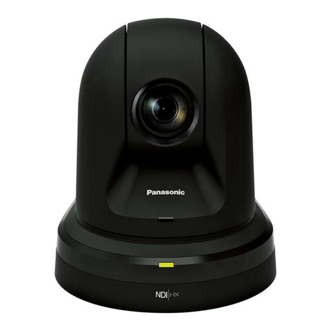
Messoa NDR891 User manual

NETWORK CAMERA
User Manual
F34-891070-000A 891 A.1

Notice of Use
This manual is designed for administrators and users of the network camera. Please read it carefully before
use. All requirements should be followed before using this camera.
We are not responsible for any technical or typographical errors and reserves the rights to
change the product and manuals without notice.
Keep this document for future reference.
Please make sure the power source is 12V DC / 24V AC / PoE. Only connect to the camera to
this required power system.
Caution: For heater model, the power source must be 24V DC / 24V AC.
The camera must be installed on a solid mounting surface.
Keep the camera and other accessories dry.
We are not responsible for any damage caused by inappropriate use.
1

Table of Contents
Notice of Use ...............................................................................................................................1
1. Overview ..................................................................................................................................4
1.1 Key Features ......................................................................................................................4
1.2 Package Contents ..............................................................................................................4
1.3 Physical Descriptions .........................................................................................................5
1.3.1 Dimension ................................................................................................................5
1.3.2 Connectors ...............................................................................................................5
1.3.3 Controls ....................................................................................................................6
1.4 Specifications .....................................................................................................................7
2. Camera Installation.................................................................................................................9
2.1 Ceiling Mount .....................................................................................................................9
2.2 Adjusting the Camera.......................................................................................................10
3. Network Connection and Configuration .............................................................................12
3.1 Network Connection Types ..............................................................................................12
3.2 Accessing the Camera for the First Time .........................................................................14
3.3 Using “IP Finder” to Manage Cameras.............................................................................16
3.3.1 Installing IP Finder..................................................................................................16
3.3.2 Using IP Finder.......................................................................................................16
4. Using Web-based Control Utility .........................................................................................19
4.1 Overview ..........................................................................................................................19
4.1.1 Main Screen ...........................................................................................................19
4.1.2 Setup Menu ............................................................................................................20
4.1.3 Applying Settings....................................................................................................20
4.2 Image Settings .................................................................................................................20
4.2.1 Codec .....................................................................................................................20
4.2.2 Exposure ................................................................................................................23
4.2.3 White Balance ........................................................................................................26
4.2.4 Basic Settings.........................................................................................................27
4.2.5 Smart Encoding......................................................................................................28
4.2.6 Smart Focus ...........................................................................................................29
4.2.7 Privacy Zone ..........................................................................................................30
4.2.8 ePTZ.......................................................................................................................31
4.3 Network ............................................................................................................................32
4.3.1 Basic.......................................................................................................................32
4.3.2 FTP.........................................................................................................................32
4.3.3 SMTP .....................................................................................................................33
4.3.4 NTP ........................................................................................................................34
4.3.5 RTSP......................................................................................................................34
4.3.6 ONVIF ....................................................................................................................35
4.4 System .............................................................................................................................36
4.4.1 Date and Time........................................................................................................36
4.4.2 Time Stamp ............................................................................................................37
4.4.3 Firmware ................................................................................................................37
2

4.4.4 User Management..................................................................................................39
4.4.5 Language ...............................................................................................................40
4.4.6 Log .........................................................................................................................40
4.4.7 Audio ......................................................................................................................41
4.5 Event ................................................................................................................................42
4.5.1 Motion Detection ....................................................................................................42
4.5.2 External Alarms ......................................................................................................43
4.5.3 Blur Detection.........................................................................................................44
4.5.4 Audio Detection ......................................................................................................45
4.5.5 Ethernet Detection..................................................................................................46
4.5.6 Event Management ................................................................................................46
4.6 Recording .........................................................................................................................47
4.6.1 Settings – Video Clip ..............................................................................................47
4.6.2 Settings – FTP........................................................................................................47
4.6.3 Settings – SMTP ....................................................................................................48
4.6.4 Settings – SD Card.................................................................................................49
4.6.5 Period Settings .......................................................................................................49
5. Using VLC Player to Access RTSP Streaming...................................................................51
3

1. Overview
1.1 Key Features
High Definition Images
Clear and detailed HD quality images in all conditions. Unlike traditional megapixel cameras, HD offers
higher resolutions and better frame rates at an international industry standard. Blurry images are reduced
and individuals and objects of interest come through in perfect clarity.
Triple Streaming
The Network Dome Camera is a high performance HD camera designed to show extreme image detail.
H.264/MPEG4/MJPEG triple streaming allows you to choose the appropriate codec for your bandwidth.
Using a video player (VLC player…etc), you can view your RTSP stream from anywhere.
Cost-saving H.264 Support
The Network Dome Camera supports the H.264 compression standard. H.264 greatly reduces the size of
video compared to MJPEG and MPEG4 without compromising image quality. Storage and bandwidth
needs are reduced. Plus, H.264 is expected to become the video standard of choice, so your camera is
future proofed.
1.2 Package Contents
The Network Dome Camera package includes these items:
Network Dome Camera x1
Quick Start Guide x1
CD-ROM x1
Guide Pattern Sticker x1
RJ-45 Female / Female Coupler x1
Accessories:
- 1. Flat Head Screw (Tapping Type) x3
- 2. Plastic Anchor x3
- 3. Flat Head Screw (Machine Type) x3
4

1.3 Physical Descriptions
1.3.1 Dimension
1.3.2 Connectors
Power In (Red+/Black-): Connects to DC 12V / AC 24V power supply. If you are to use power
from Ethernet connection, this connector is not used when the power is provided by PoE.
Note: Camera with heater requires DC24V/ AC24V power supply.
RJ-45 Ethernet Connector: Connects to the LAN port of a standard 10Base/100Base-TX device,
e.g., hub, switch or router.
BNC: Connects to composite video in connector of a monitor. Note that when connecting the
camera to an analog monitor, the camera must be connected to DC 12V / AC 24V power supply.
Audio Out (Green): Connects to speaker.
Audio In (Red): Connects to an external microphone.
Alarm Out (Orange): Connects to device that responds to alarm signals, such as buzzers or
lights.
Reserved (Green)
5

RS485 (Yellow)
GND: Ground (electricity) in electrical circuits
Alarm In 1 (Red) & 2 (Brown): Connects to devices that trigger alarm signals. Up to two 2 input
devices can be connected.
1.3.3 Controls
Reset: use an appropriate tool to press the button for few seconds to reset the camera
Hold for 5 seconds to reboot camera. Hold longer than 5 seconds to load default settings.
Zoom: Adjust the zoom control for desired image view.
Focus: Adjust the focus for optimum picture sharpness.
Focus (Far/Near)
Zoom (Tele/Wide)
6

1.4 Specifications
Image System
Image Sensor 1/3" 2 MP image sensor optimized for low-light performance
Image Compression Method Triple Streaming : H.264 / MPEG4 / Motion JPEG
Maximum Frame rate vs.
Resolution
HDTV 1080p(1920x1080) at 15 fps (NTSC) and 12.5 fps (PAL)
and 2MP 16:9 (1280x720) at 30 fps (NTSC) and 25 fps (PAL)
Lens Built-in Mechanical IR Cut Filter varifocal lens f=3~9mm, F1.2 (Mega pixel lens)
View Angle H: 93°(Wide)~31.7°(Tele)/V:68.4°(Wide)~23.8°(Tele)
View Angle Adjustment Pan:0°-360°(Max.), Tilt:10°-90°(Max.), Rotate:0°-360°(Max.)
Electric
Shutter Time Range from 1/10,000s to 1/3.75s selectable (60Hz);
Range from 1/10,000s to 1/3.125s selectable (50Hz)
Audio Two-way Mono Audio, Full-duplex, G.711 PCM 8kHz
Alarm External input
RS485 Reserve
Day/Night Mode Mechanical D/N control; Auto/ Forced BW/ Forced Color/ External
Minimum illumination IR LED OFF: 0.06 Lux @10IRE; 0.24Lux @50IRE (shutter speed: 1/15sec)
IR LED ON: 0lux
IR LED IR LED 20pcs(850nm)
IR Distance 25 meters (82 ft.)
IR turn on status Under 10 lux by auto control
LED Life More than 10,000 hours (50ºC)
Video Port BNC X1, 1.0Vp-p, 75Ω/ RCA x 1
Video Output NTSC: 720 X 480 @30fps;
PAL: 720 X 576 @25fps
Image Enhance
Exposure Mode: Auto/Manual
White Balance: Auto/Manual
Backlight Compensation: 5x5 zones selectable
Sharpness, saturation, brightness, contrast: 255 level sensitivity
Feature Brief
Digital WDR Yes; 5 level sensitivity
Privacy Zone Yes; customized threshold privacy zone
Intelligent Video Audio detection / Blur detection / Ethernet Detection/ Smart Encoding/ Smart
Focus/ e-PTZ/ Event Management
Alarm Detection
Motion Detection: 5 x 5 zones, 5 level sensitivity or customized threshold
Audio Detection: 5 level sensitivity or customized threshold
Blurt Detection: customized threshold
External Input
Alarm Event
File upload via FTP, SMTP and SD Card
Notification via email, HTTP and TCP
External output activation
Video and audio recording to SD Card
Text Overlay (to be
developed) Yes
Image Orientation Mirror, Flip
Local Storage
Memory Card Micro SD/ Micro SDHC Card up to 32 GB
7

SD Card Overwrite Yes
SD Card Store Category Alarm / Motion / Schedule/ Un-interrupt recording
Power supply
Power Requirement DC 12V & AC 24V ± 10%;
PoE(IEEE 802.3af) DC24V/AC24V± 10%
Power Connector Screwless Terminal block
Power consumption (Max.) 8W 8 W (heater on)
20 W (heater off)
Environment
Operating Temperature -10ºC ~ 50ºC (-14ºF ~ 122 ºF) -40ºC ~ 50ºC (-40ºF ~ 122 ºF)
Operating Humidity 10~ 90% RH
Storage Temperature -20ºC ~ 60ºC (-4ºF ~ 140 ºF)
Regulatory CE, FCC, RoHS
Network
Ethernet 10Base-T/100Base-TX Ethernet connection for LAN / WAN, RJ-45
Internet Protocol IPv4, TCP/IP, UDP, HTTP, SMTP, DNS, DHCP, NTP, FTP, RTP,RTSP, ICMP,
UPnP
Browser IE browser 6.0 or above
I/O connector
Alarm Port Terminal block 2 in / 1 out
Audio In / Out port 3.5mm Phone Jack x 2
Reset Within 5 sec for rebooting system; more than 5 sec for loading default
Mechanism
Dimensions(ΦxH) Φ142mmx 120.8mm (Φ5.6 in x 4.8in)
Weight 1.3kg
Protection Class IP67, vandal-proof
Option Without Heater With Heater
Accessory
Mount Type Surface mount: standard package support
Pendent mount: thread 1", Wall mount
8

2. Camera Installation
CAUTION! For heater model, the dome cover should NOT be removed over 30 minutes during
installation. Otherwise, the desiccant will absorb too much moisture causing vapor when heater is on.
2.1 Ceiling Mount
1. Remove the dome cover and the inner liner.
Use a security torx screwdriver to loosen (but not remove) the 3 cover screws.
Remove the inner liner by gently pulling it free from the two notches on the camera base.
2. Use the Guide Pattern Sticker to drill the mounting holes.
Place the provided “Guide Pattern Sticker” on the desired mounting location. Drill three mounting
holes and one cable entry hole according to the guide pattern.
3. Connect the wiring and optionally insert the SD card.
Draw out the cabling to the connecting places. Refer to “1.3.2 Connectors” section to make
connections as required. If using SD card function, insert the Micro SD/SDHC card.
To adjust the field of view and focus, you can optionally connect a monitor to the Video out RCA jack
at this point. If no monitor is available, then focus must be performed by using an Internet browser to
view the camera images.
Caution: For DC power supply use, make sure the polarity is correct to avoid malfunction and / or
camera damage.
4. Secure the camera base to the surface.
Use appreciate screws according to the mounting surface material. If required, you may require
different screws and anchors than those supplied.
For cement surface:
Insert the provided plastic anchors into the three drilled holes. Then secure the camera base to the
mounting surface with the provided tapping type screws.
For metal plate surface:
Do not use the plastic anchors. Just secure the camera base to the mounting surface with the
provided machine type screws.
5. Adjust the camera position and focus.
Adjust the focusing position by rotating and panning the camera base. Adjust the lens using the Zoom
and Focus controls.
6. Install the inner liner.
Fit the camera liner over the camera base so that it snaps into place.
7. Replace the dome cover.
Put the dome cover over the base and tighten the 3 cover screws.
9

Guide Pattern
Plastic Anchors
Service Monitor Output
Micro SD card slot
Dome base
Tapping Type Screw
inner Liner
Dome Cover
2.2 Adjusting the Camera
Pan adjustment: Rotate the lens base to adjust the horizontal angle.
Tilt adjustment: Tilt the lens base to adjust the vertical angle.
Horizontal rotation: Rotate the dome base to adjust the horizontal position. Do not turn the base more
than 355° as this may cause the internal cables to twist and disconnect or break
Horizontal Rotation (maximum 355)
Pan (maximum 355)
Tilt (maximum 90)
10

Note: When the tilt angle is less than 75 degrees there is no distortion.
Lens Adjustment: Loosen the screws and adjust the zoom control for desired image view and adjust the
focus for optimum picture sharpness. Re-tighten the screws after focus adjustments are done.
Focus (Far/Near)
Zoom (Tele/Wide)
11

3. Network Connection and Configuration
3.1 Network Connection Types
There are many different ways that you can connect the camera to your network, depending on your
applications requirements. You should always set the camera’s network settings according to your
network configurations. The following diagrams depict some typical applications with guidelines on
network settings. For more information on network settings, always consult with your network
administrator or ISP as required.
Type 1— Direct Connection to a PC
Directly connect the camera to a PC using a standard Ethernet cable.
To extend the connection length, you should use a RJ45 female/female coupler to connect two Ethernet
cables together.
RJ45 coupler
Note:The LAN port of the camera supports auto MDI/MDIX (Medium dependent interface crossover) so
there is no need to use cross-over cable.
To access the camera, the PC must be on the same network as the camera. The default IP address of
the camera is a static one (192.168.1.30). Configure your PC’s IP address as 192.168.1. X (where X is a
number between 2 to 254, excluding 168 and subnet mask as 255.255.255.0, and then your PC should
be able to access the camera.
12

Type 2: Connecting Camera(s) to a Local Area Network (LAN)
To add the camera(s) to an existing LAN, just connect the camera(s) to the hub or switch on your network.
If you want to provide the camera power via the Ethernet connection, a PoE-enabled hub/switch is
required.
Note: The LAN port of the camera supports auto MDI/MDIX (Medium dependent interface crossover) so
there is no need for an uplink port or the use of a cross-over cable.
Assign an IP address to your camera following your network IP allocation policy. You can manually
specify the IP address or allocate the IP address automatically using a DHCP server, if available on your
network.
Then, you can monitor and mange the camera via a web browser from a local PC.
Hub/Switch or PoE Hub/Switch
Type 3: Remote Connection via the Internet
If the network where the camera resides is connected to the Internet, you can also provide remote access
to your camera over the Internet.
Typically a broadband router has a built-in DHCP function to assign a local IP address to your camera.
You can alternatively assign a fixed IP address to the camera to prevent it from frequently changing.
Private IP
External IP
DSL/Cable
Modem Router
To access the camera from a local PC, simply use the local IP address of the camera.
To enable remote access, you must configure your router/firewall to forward an incoming request to that
fixed local IP address of the camera. Therefore, when an external host sends a request to access your
camera, the request will first reach the router’s external IP address and then be forwarded to the local IP
address of the camera.
13

Port forwarding is based on the service you want to provide. For example, forward HTTP port to enable
remote web access to your camera, or RTSP port to enable access to video/audio streams from the
camera.
If your camera is configured to use a non-standard HTTP port, then you have to forward that port
accordingly.
3.2 Accessing the Camera for the First Time
The camera comes with a web-based setup utility, allowing you to view the video of the camera and
configure the camera for optimal use in your environment.
To access the camera’s web-based control utility, you need a PC that meets the following requirements:
Operating System: Windows Vista® or XP
Browser: Internet Explorer Version 6.0 or later
CPU: Intel Pentium 4.2 GHz or higher
RAM: 512 MB or more
Then take the following steps to connect your PC to the camera.
Step 1: Make the connection
For initial setup purposes, connect one end of an Ethernet cable to the RJ45 connector of the camera and
the other end to the LAN port on your PC.
Step 2: Configure your PC’s IP address
The camera uses a default IP address of 192.168.1.30 and
subnet mask of 255.255.255.0. To have your PC on the same
network with the camera, configure your PC’s IP settings as
below:
IP address: 192.168.1. X, where X is a number
between 2 to 254, excluding 30.
Subnet mask: 255.255.255.0.
Ignore all other settings and click OK.
14

Step 3: Verify the connection between the PC and the IP Cam
1. Launch the Command Prompt by clicking the Start menu, Programs, Accessories and then
Command Prompt.
2. At the prompt window, type ping x.x.x.x, where x.x.x.x is the IP address of the camera (the
default is 192.168.1.30).
If the message of “Reply from…” appears, it means the connection is established.
Step 4: Access the camera from IE browser
Open the IE browser and enter the IP address of the camera in the URL field. The default is 192.168.1.30.
When prompted to login, enter the user name and the password. (The defaults: admin, 1234). Note that
the password is case-sensitive.
15

Upon successful login, you will see the live view screen shown as the example below:
3.3 Using “IP Finder” to Manage Cameras
IP Finder is a management tool included on the product CD. It is designed to manage your network
cameras on the LAN. It can help find multiple network cameras, set IP addresses, show connection status
and manage firmware upgrades.
3.3.1 Installing IP Finder
Before proceeding, make sure your operating system is Windows Vista or Windows XP.
To install the software, simple locate and double-click the IP Finder setup file on the provided CD. Then
follow the on-screen prompts to proceed.
3.3.2 Using IP Finder
To launch IP Finder, double-click the IP Finder shortcut on the desktop or click Start > Programs > IP
Finder > IP Finder.
After you launch IP Finder, it will search for all the available cameras on the same network. Click the plus
sign next to “All Devices” to expand the menu and display all the found cameras.
Clicking a target camera will show the live view (if available) and the detailed information of the camera,
including the MAC address. Each camera comes with a unique MAC address, which is indicated on the
16

product label. It helps identify which camera is currently accessed, particularly when multiple cameras are
connected on your network.
The Tool menu of the IP Finder allows you to perform these tasks:
Search Network: This option allows you to search the cameras on the network.
Set Master ID and Password: Allows you to set a master ID and password for managing the
cameras with IP Finder.
Management Tool: Allows you to restart the camera, update firmware, reset all of the camera
settings to default (except network settings) and reset all of the camera parameters to default.
17

For an individual camera, right-click the camera and a menu will provide these options:
Go to Presentation URL: Launch IE browser to access the web-based utility of the camera.
Set Device ID and Password: Set the login ID and password for managing the camera with IP
Finder.
Network Information: Allows you to configure the camera’s network settings.
18

4. Using Web-based Control Utility
4.1 Overview
4.1.1 Main Screen
After you login to the camera’s web-based control utility, you will first see the live view screen of the
camera. The screen is like the picture below:
Snapshot button
Live view button
Setup button
Camera name
A
larm Indicato
r
Recording Indicator
Live view video
The live view screen of the utility provides these options:
Snapshot:Pressing this button takes a snapshot of current live view screen.
Live: Pressing this button displays the live view of the camera.
Setup: Pressing this button allows you to access the setup page.
Camera name: Displays the name of the camera.
Recording Indicator: Turns red only when the recording is proceeding.
Alarm Indicator: Appears when an alarm is triggered.
Live view video: Shows the live view of the camera.
19
Other manuals for NDR891
1
Table of contents
Other Messoa Security Camera manuals
Messoa
Messoa SCR368-HN5 User manual
Messoa
Messoa NIC990 User manual
Messoa
Messoa NCB355 User manual
Messoa
Messoa SCB267-HN5 User manual
Messoa
Messoa NOD316 User manual
Messoa
Messoa SCR367 User manual
Messoa
Messoa NDF831-HN5 User manual
Messoa
Messoa NCR870 User manual
Messoa
Messoa SCR515PRO User manual
Messoa
Messoa SCB280 User manual
Messoa
Messoa NDF821 User manual
Messoa
Messoa NDR890-HN5 User manual
Messoa
Messoa NDR891(H) User manual
Messoa
Messoa SCR510HB-HN2 User manual
Messoa
Messoa PTZ900 User manual
Messoa
Messoa SPD982 User manual
Messoa
Messoa NDF820 User manual
Messoa
Messoa NDF821PRO User manual
Messoa
Messoa NCB750 User manual

Messoa
Messoa NCB750 User manual
