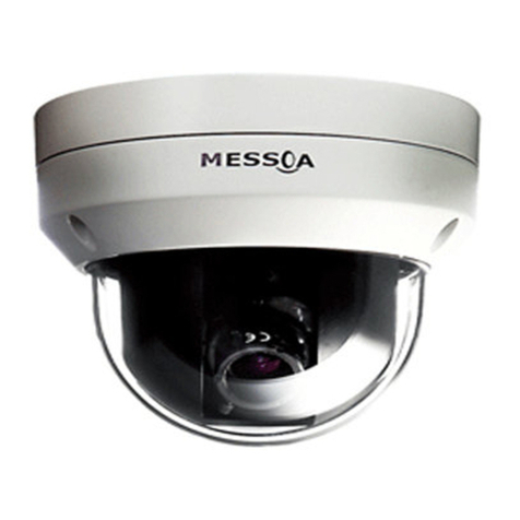
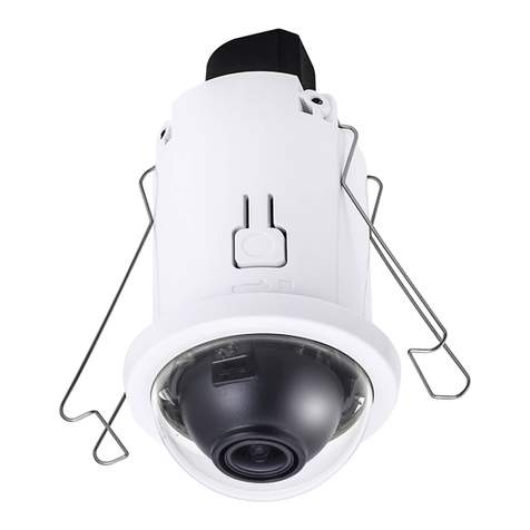
Messoa NID318 User manual

Indoor IR Dome Network Camera
Quick Start
Guide
201505 318 706 A1
NID318
UFD706

1
English
WARNING
●This unit operates at PoE (IEEE 802.3af Class 0).
●Installation and service should be performed only by qualied and experienced technicians and comply with all local codes and rules to maintain
your warranty.
●To reduce the risk of re or electric shock, do not expose the product to rain or moisture.
●Wipe the camera with a dry soft cloth. For tough stains, slightly apply with diluted neutral detergent and wipe with a dry soft cloth.
●Do not apply benzene or thinner to the camera, which may cause the surface of unit to be melted or lens fogged.
●Avoid aligning the lens to very bright objects (example, light xtures) for long periods of time.
●Avoid operating or storing the unit in the following locations:
» Extremely humid, dusty, or hot/cold environments (recommended operating temperature: -10°C to +50°C)
» Close to sources of powerful radio or TV transmitters
» Close to uorescent lamps or objects with reections
» Under unstable or ickering light sources
WEEE (Waste Electrical and Electronic Equipment). Correct disposal of this product (applicable in the European Union and other European
countries with separate collection systems). This product should be disposed of, at the end of its useful life, as per applicable local laws,
regulations, and procedures.
FCC Compliance Statement
Information to the user: This unit has been tested and found to comply with the limits for a Class B digital device pursuant to Part 15
of the FCC Rules. Operation is subject to the following two conditions: (1) this device may not cause harmful interference, and (2) this
device must accept any interference received, including interference that may cause undesired operation. These limits are designed
to provide reasonable protection against harmful interference in a residential installation. This unit generates, uses, and can radiate radio
frequency energy and, if not installed and used in accordance with the manual, may cause harmful interference to radio communications.
However, there is no guarantee that interference will not occur in a particular installation.
If this unit does cause harmful interference to radio or television reception, which can be determined by turning the unit o and on, the user is
encouraged to try to correct the interference by one or more of the following measures:
●Reorient or relocate the receiving antenna.
●Increase the separation between the unit and receiver.
●Connect the unit to an outlet on a circuit dierent from that to which the receiver is connected.
●Consult the dealer or an experienced radio/TV technician for help.
Caution Changes or modications not expressly approved by the party responsible for compliance could void the user’s authority to operate the unit.
CE Statement
Operation is subject to the following two conditions: (1) this device may not cause harmful interference, and (2) this device must
accept any interference received, including interference that may cause undesired operation. The manufacturer declares that the
unit supplied with this guide is compliant with the essential protection requirements of EMC directive and General Product Safety
Directive GPSD conforming to requirements of standards EN55022 for emission, EN 55024 for immunity, EN 300 and EN 328 for WIFI.

2
English
1 Product Overview
Figure 1 - 1: Physical dimension
Table 1 - 1: Pictorial Index Denition
Figure 1 - 2: Pictorial Index
Index Name
1 Camera Body
2 Bottom Conduit Hole with Plug
3 Top Cover
4 Latch buttons x 2
5 Side Conduit Hole with Plug
1
2
345
1.1 Physical Characteristics

3
English
Figure 1 - 3: I/O Connector
Index Name Description
1 Micro SD card slot To insert a micro SDHC/SDXC card into this slot for recording and storage
2 Reset button Press the button to reboot the camera.
3 Default button Press the button for 5 seconds to restore the camera back to the factory default
setting.
4RJ-45 Ethernet
Connector/ PoE
To insert the RJ-45 cable for network connection along with PoE (Power over
Ethernet) capability.
Orange LED
The LED will be solid on when link is initiating well. And with
flashing orange, the LED indicates package data is being
transmitted / received between camera and Internet.
Green LED
With solid green, the LED signies connection bandwidth is
established under 100Mbit/s.
Without solid green, the LED signies connection bandwidth
is established under 10Mbit/s.
Table 1 - 2: I/O Denition
1
2
3
4

4
English
2 Installation
2.1 Package Content
Check everything in the packing box matches to the order form and the packing slip. In addition to this manual, items below
are included in the packing box.
●One Network IR dome camera
●One printed quick installation guide
●One mounting template
●Two screw anchors
●Two screws
Please contact your dealer if any item missing.
2.2 Installation
Following tools might help you complete the installation:
●a drill
●screwdrivers
●wire cutters
2.2.1 Checking Appearance
When rst unboxing, please check whether if there is any visible damage to appearance of the camera and its accessories.
The protective materials used for the packaging should be able to protect the camera from most of accidents during
transportation. Please remove the protective materials when every item is checked in accordance with the list in Package
Content.
2.2.2 Disassembling the Camera
Please refer to the steps with gures below for correct disassembling order.
1. Press and hold the both left and right latch buttons on the top cover.
2. Gently pull the top cover downward to take apart it from the camera body.
Figure 2 - 1: Disassembling The Camera
Left Latch Button Right Latch Button

5
English
2.2.3 Connecting the wires
After disassembling, the PoE RJ-45 Ethernet port is visible on the camera body for user to connect Ethernet cable for both
powering and network connectivity purposes. The camera, equipped with side and bottom conduit holes, can be passed
through network cable in dierent ways to t varied applications. Refer to the following gures and descriptions for specic
details.
Side Conduit Cabling: remove the side conduit plug to allow network cable to pass through the side conduit hole. Please make
sure to completely tuck the bottom conduit plug into the bottom conduit hole in case dusts permeate the camera.
Bottom Conduit Cabling: pull out the bottom conduit plug to allow network cable to pass through the bottom conduit hole.
Please make sure to seal o the side conduit plug entirely on the top cover to free from dusts penetrating inside the camera.
Figure 2 - 2: Side Conduit Cabling Figure 2 - 3: Bottom Conduit Cabling
2.2.4 Mounting the camera
Step 1. Mounting Preparation
Paste the included guide pattern onto a wall/ceiling where the IP camera is about to be located, and drill 2 hole patterns in
accordance with the indications on the guide pattern (2-Ø4.5 Holes) followed by hammering the 2 plastic anchors into the
drilled holes. Also, drill another hole for cable threading as the indication for bottom conduit installation (Ignore drilling cable
hole if applying side conduit method).
Figure 2 - 4: Guide Pattern
Step 2. Mounting the Camera
Attach the camera to the predened surface properly and fasten the 2 screws into the plugged screw anchors securely to x
the camera on the location.
Figure 2 - 5: Mounting the Camera

6
English
Step 3. Assembling the camera
Install the top cover upward to assemble the camera completely. The camera is thus stably xed on the surface.
Figure 2 - 6: Assembling and Completing Camera Mounting
2.2.5 Adjusting the camera position
The unit has three axes for adjusting eld of view on dierent applications. While screening live view on your monitor, adjust
the position by procedures below simultaneously for desired focusing position.
●Pan Adjustment (A)
Rotate the lens base until satised with the eld of view. Note that the bottom conduit hole of camera body is the point
where the camera lens shouldn’t be rotated over.
●Horizontal Rotation (B)
Rotate 3D assembly in the lens, but do not turn assembly more than the limit as this may have the internal cables
twisted, disconnected, or broken.
●Tilt Adjustment (C)
Adjust the camera lens tiltedly within the certain range (35° - 90°) to your desired eld of view.
Figure 2 - 7: Adjusting the Camera Position
Caution
Limitation for three axes position:
Pan range : ±177°
Rotate range : ±177°
Tilt range : 35°~90°
A
B
C

7
English
The camera, which is equipped with Ethernet RJ-45 network interface, can deliver video images in real time via either Internet
or Intranet. Please refer to the skeleton drawings shown below for understanding.
Figure 3 - 1: Network Topology
3 Connection
3.1 Network Topology
Below table lists the minimum requirement to implement and operate the unit. No hardware/software component inferior to
the requirements is recommended.
Table 3 - 1: System Requirements
System Hardware
CPU Intel Pentium 4 2.4GHz or equivalent
RAM 1 GB or above
Display NVIDIA GeForce 6 Series or ATI Mobility Radeon 9500
System Software
Operating System Microsoft Windows XP, Windows Vista, Windows 7 or above
Browser Microsoft Internet Explorer 9~11, Chrome, Firefox
Unit
Power Supply PoE (IEEE 802.3af Class 0)
Networking
Wired* 10/100BASE-T Ethernet (RJ-45 connector)
*a switch is required for surveillance on multiple units.
Note All the installation and operations should comply with your local electricity safety rules.
3.2 System Requirements
3.3 Connecting Process
3.3.1 Default IP address
Since this is a network-based unit, an IP address must be assigned at the very rst. The unit’s default IP address is 192.168.1.30
and sub mask is 255.255.255.0. However, if you have a DHCP server in your network, the unit would obtain an IP address
automatically from the DHCP server so that you don’t need to change the camera’s IP address. But be sure to enable DHCP in
"Network Settings".

8
English
3.3.2 Connecting from a computer & Viewing Preparation
Connecting from a computer
1. Make sure the unit and your computer are in the same subnet.
2. Check whether if the networking available between the unit and the computer by executing ping the default IP address. To
do this, simply start a command prompt (Windows: from the Start Menu, select Program. Then select Accessories and choose
Command Prompt.), and type “Ping 192.168.1.30”. If the message “Reply from…”appears, it means the connection is available.
3. Start a browser e.g. Internet Explorer and enter IP address: 192.168.1.30. A login window should pop up. In the window, enter
the default user name: admin and password: 1234 to log in.
Further administration on the unit can be found in“User Manual".
Figure 3 - 2: Login Window
Viewing Preparation
Images of the unit can be viewed through various browsers. Before viewing, follow these steps to enable the display.
4. Enable Cookies as instructions below
●In Internet Explorer, click Internet Options on the Tools menu.
●On the Privacy tab, move the settings slider to Low or Accept All Cookies.
●Click OK.
5. When a proxy server is used, click Internet Options on the Tools menus of Internet Explorer, select Connect tab, click LAN
button, and set proxy server.
6. Change Security in Internet options as instructions below
●On tool menu, click Internet Options.
●Press the Security tab.
●If the camera operates inside of the intranet, click the Intranet icon.
●If the camera operates outside of the intranet, click the Internet icon.
●Click Custom Level. This will open the Security Settings – Internet Zone screen.
Figure 3 - 3: Security Settings 1/4

9
English
●Scroll down to the ActiveX controls and plug-ins radio buttons and set as follows:
【Download signed ActiveX controls】→ Prompt (recommended)
【Download unsigned ActiveX controls】→ Prompt
【Initialize and script ActiveX not marked as safe for scripting】→ Prompt
Figure 3 - 4: Security Settings 2/4
【Automatic prompting for ActiveX controls】→ Enable
Figure 3 - 5: Security Settings 3/4
【Run ActiveX controls and plug-ins】→ Enable
【Script ActiveX controls marked safe for scripting*】→ Enable
Figure 3 - 6: Security Settings 4/4
●Press OK to save the settings.
●Close all your browser windows and restart a new window. This will allow the new settings taking eect.
●Type your setting IP address into the browser.
●Then you should be able to see the camera image screen.

10
English
IP Finder is a utility program that helps users to locate the unit in local area network that computer is connected to. Please
note that IP Finder works only in Microsoft Windows XP, Microsoft Windows Vista, and Microsoft Windows 7 or above. Steps to
get the utility program running are listed below.
1. Download IP Finder from MESSOA Website to the computer.
2. Double click on IPFinder.exe in computer’s IP Finder folder, and the IP Finder window should pop out.
3. The window would list information of units in operation at present. Press FIND CAMERA to nd more units.
4. Locate and double-click one of the cameras in the list you want to congure the network settings. If you have multiple cameras
connected to your local network, locate the MAC address on the camera to distinguish the target camera from others.
5. Congure the following settings as needed.
●NAME: Enter a descriptive name for the camera.
●NETWORK SETTINGS: If you have a DHCP server on your network to assign IP addresses to network devices, enable the
DHCP option. Otherwise, manually enter the IP ADDRESS, NET MASK and GATEWAY values.
●USERNAME & PASSWORD: Manually setup preferred username and password.
●SET: Whenever you make revision of camera settings, click“SET” to take eect.
●SW DEFAULT: To perform the factory defaults excluding network settings of the selected camera.
●HW DEFAULT: To perform the factory defaults of the selected camera.
●RESET: To reboot the selected camera.
Click Save to enable the settings and click Exit to exit the utility.
Figure 3 - 7: IP Camera Finder
3.4 IP Finder

11
简体中文
注意事项
●该摄像机使用PoE供电。
●请由专业技术人员安装和维修摄像机,确保符合当地规程并保证您的保修权限。
●请勿将摄像机放置于雨水或潮湿的环境中,以免发生火灾或触电危险。
●请使用柔软的干布清洁摄像机。如有顽固污渍,请用抹布蘸取少量中性洗涤剂清洁,然后擦干。
●请勿使用苯或稀释剂,以免导致摄像机表面物质溶化或镜头雾化。
●请勿将镜头长时间对准强光源(如照明器具)。
●避免在以下地点使用或存放摄像机:
»极度潮湿、多尘、极热/冷的环境(建议运作温度范围[-10°C ~ +50°C] )。
»靠近强磁场或电磁辐射源。
»靠近荧光灯或反光物体。
»在不稳定光源下(可能引起闪烁)。
废弃电子电气设备指令
废弃后请正确处理此物 ( 本指令案在不违背欧盟和其他欧洲国家废物分类管理的特殊法规的前
提下适用 )。摄像机废弃后,应按照当地“电子电气废弃物”规章制度进行处理。
CC 章程声明
用户须知:该摄像机经测试符合 B 级数字设备标准,符合 FCC 章程 15 部分的规定。操作本设备必须遵循以下两个条件:(1)
不对周围环境产生有害干扰。(2)该设备须接受任何收到的外部干扰,包括可能影响该设备正常工作的干扰。这些限制标
准为防止此设备在住宅区使用时产生有害干扰,此设备使用并放射无线电频率,如不按照标准正常安装使用,可能会对无线
电通讯造成有害干扰。然而,我们无法保证采用何种安装模式可以完全避免干扰。
如果开启或关闭该设备时发现其对无线电或电视接收造成干扰,用户可尝试以下几种方法修复干扰:
●调整或重置接收天线
●将此设备远离其他信号接收设备
●将此设备与其他信号接收设备分配在不同电路中
●咨询经销商或经验丰富的无线电/TV技术员
警告 任何不遵守许可的改动或者修改可能会使用户的操作权限无效。
CE 认证
操作本设备必须遵循以下两个条件:(1)不对周围环境产生有害干扰。(2)该设备须接受任何收到的外部干扰,包括可能
影响该设备正常工作的干扰。本设备及此快速安装指南符合电磁相容 EMC 指令与《通用产品安全指令》(GPSD)要求的产
品系列标准,符合 EN55022(关于排放)、EN 55024(抗干扰性)的要求及 EN 300 和 EN 328 无线产品法规。

12
简体中文
1 产品概述
图 1-1:外形尺寸
表 1-1:图示索引定义
图 1-2:图示索引
索引 定义
1 摄像机机身
2 底部出线孔,带孔塞
3 上盖
4 锁扣按钮 x 2
5 侧面出线孔,带孔塞
1
2
345
1.1 外形特征

13
简体中文
图 1-3:I/O 接口
索引 名称 定义
1 SD 卡槽 插入 SDHC/SDXC 卡,存储影像文件。
2 复位按钮 按下此按钮重启摄像机。
3 默认按钮 长按此按钮 5 秒,摄像机所有设置恢复出厂默认值。
4RJ-45 网络接口 /
PoE 接口
插入 RJ-45 网线,连接网络或进行 PoE 供电
橘黄色 LED 连接启动后,橘黄色 LED 灯点亮。摄像机和互联网之间
进行数据传输 / 接收时,橘黄色 LED 灯闪烁。
绿色 LED 绿色 LED 灯恒亮表示连接带宽为 100Mbit/s。
绿色 LED 灯不保持恒亮表示连接带宽为 10Mbit/s。
表 1-2:I/O 接口定义
1
2
3
4

14
简体中文
2 摄像机安装
2.1 标准配备
检查接收到的物品与订单和装箱单上所列的是否相符,除了此份使用手册,还应包含以下物品:
●红外半球摄像机(x1)
●纸质档快速安装指南(x1)
●定位贴(x1)
●塑胶壁虎(x2)
●螺丝(x2)
如有任何部件遗失或损坏,请联系该摄像机的经销商。
2.2 安装
安装前,请准备相关工具:
●钻孔机
●螺丝刀
●剪线钳
2.2.1 检查外观
首次拆箱打开时,请检查摄像机及其配件外观是否有损坏。我们的包装均采用防护材料,防止运输过程中损伤货物。
根据“2.1 标准配备”中的装箱清单检查物品,然后去掉产品外部保护膜。
2.2.2 拆卸摄像机
请参考下列步骤顺序拆卸摄像机:
1. 用力按住上盖左右两侧锁扣按钮。
2. 轻轻向下拉,从摄像机机身上取下上盖。
图 2-1:拆卸摄像机
左侧锁扣按钮 左侧锁扣按钮

15
简体中文
2.2.3 接线
取下摄像机上盖后可看到摄像机机身上的 RJ-45 网络接口,插入网线连接网络或进行 PoE 供电。摄像机底部和侧面都
有一个出线孔,连接网线时用户可根据需要选择其中一个出线孔。请参考下图和说明了解更多细节内容。
●侧面出线孔接线:取下侧面出线孔孔塞,然后将网线穿过此出线孔。同时插入底部出线孔孔塞,密封出线孔,防止灰尘
渗透进入摄像机。
●底部出线孔接线:取下底部出线孔孔塞,然后将网线穿过此出线孔。同时插入侧面出线孔孔塞,密封出线孔,防止灰尘
渗透进入摄像机。
图 2-2:侧面出线孔接线 图 2-3:底部出线孔接线
2.2.4 安装摄像机
第一步:安装准备
将定位贴粘贴到墙壁 / 天花板上的指定安装位置,根据定位贴上孔洞位置钻 2 个孔(2-Ø4.5 Holes),插入塑胶壁虎。
如选择底部出线孔接线,需要再根据定位贴上 CABLE Hole 钻一个出线孔(选择侧面出线孔接线时则不需要钻此安装
孔)。
图 2-4:定位贴
第二步:安装机身
摄像机机身放置到预先确定好的安装位置,将 2 颗螺丝拧入塑胶壁虎中,确保摄像机机身固定到指定安装位置。
图 2-5:安装机身

16
简体中文
第三步:安装上盖
将上盖安装到摄像机机身上,完成整个摄像机安装步骤。
图 2-6:安装上盖,完成安装步骤
2.2.5 调节摄像机位置
该摄像机支持 3 轴旋转。用户观看监控画面时,可按下列步骤调整摄像机位置:
●平移调节 (A)
旋转镜头底座直到获得满意的视角,注意摄像机机身底部出线孔,请勿旋转超过此位置。
●水平旋转 (B)
旋转镜头上的 3D 零件,请勿旋转超过极限位置,以免导致内部电缆扭断裂或损坏。
●倾斜调节 (C)
请在指定范围内调节倾斜角度 (35° - 90° ) ,获取满意的拍摄视角。
图 2-7:调节摄像机位置
注意
三轴位置调节极限:
平移调节范围:±177°
水平旋转范围:±177°
倾斜调节范围:35° ~90°

17
简体中文
该网络摄像机带有 RJ-45 以太网接口,可通过互联网或局域网实时传输视频影像或音频数据。请参考下面的结构图了
解摄像机和网络连接方式。
图 3-1:网络布局
3 连接摄像机
3.1 网络布局
3.2 系统需求
下列表格列出了安装和操作此摄像机的最低系统需求,不建议使用低于以下要求的硬件或软件。
表 3-1:系统需求
系统硬件
CPU Intel Pentium 4 2.4GHz 或其他同等 CPU
RAM 1 GB 或更大容量
显示 NVIDIA GeForce 6 Series 或 ATI Mobility Radeon 9500
系统软件
操作系统 Microsoft Windows XP, Windows Vista, Windows 7 或更高版本
浏览器 Microsoft Internet Explorer 9~11, Chrome, Firefox
摄像机
电源系统 PoE (IEEE 802.3af Class 0)
网络
网线 * 10/100BASE-T Ethernet (RJ-45 connector)
* 连接多台摄像机时需使用交换机
注意 所有安装和操作应遵循当地用电安全规则。
3.3.1 默认 IP 地址
访问登录网络摄像机前,请先设置其 IP 地址。默认 IP 地址为 192.168.1.30,子网掩码为 255.255.255.0。若使用
DHCP 服务器,摄像机会自动获取 DHCP 服务器分配的 IP 地址,无需用户手动设置。启用 DHCP 前,在“网络 / 基
本设置”中勾选 DHCP。
3.3 网络连接步骤

18
简体中文
3.3.2 连接电脑 & 影像查看准备
连接电脑
1. 摄像机和电脑需连接在同一网段中。
2. 在命令提示符中ping摄像机的IP地址。检查摄像机是否已连接至电脑,首先,打开命令提示符窗口(Windows:从
“开始”菜单,选择“程序”>>“附件”>>“命令提示符”,点击“确定”),输入“ping 192.168.1.30”,若出现
“来自…的回复”提示,则表示连接成功。
3. 打开IE浏览器,在地址栏输入IP地址192.168.1.30,跳出登录提示框,输入默认用户名admin和密码1234。
阅读使用手册了解更多管理员设置信息。
图 3-2:登录窗口
影像查看准备
用户可以使用多种浏览器登录访问摄像机,查看摄像机中的影像。请根据以下步骤进行相关设置:
4. 启用Cookies
●打开IE浏览器,点击工具栏中的工具>>Internet选项。
●点击隐私标签,移动设置滑块至低或接受所有Cookies。
●点击确定,保存设置。
5. 使用代理服务器时,点击浏览器工具菜单中的Internet选项>>连接>>局域网设置,然后勾选“为LAN使用代理服务
器”,并设置代理服务器。
6. 设置Internet属性中的安全选项:
●点击浏览器工具菜单中的Internet选项。
●点击安全标签。
●如果摄像机在Intranet中,点击本地Intranet图标
●如果摄像机不在Intranet中,点击Internet图标
●然后点击自定义级别,打开“安全设置-Internet区域”页面。
图 3-3:安全设置 1/4

19
简体中文
●下拉滚动条至ActiveX控件和插件,并进行如下设置:
【ActiveX控件自动提示】→ 启用
【对标记为可安全执行脚本的ActiveX空间执行脚本*】→ 启用
【对未标记为可安全执行脚本的ActiveX控件初始化并执行脚本】→ 提示
图 3-4:安全设置 2/4
【下载未签名的 ActiveX 控件】→ 提示
【下载已签名的 ActiveX 控件】→ 提示(推荐)
图 3-5:安全设置 3/4
运行 ActiveX 控件和插件】→ 启用
图 3-6:安全设置 4/4
●点击“确定”,保存设置
●关闭所有IE窗口,重新开启IE窗口,所有设置生效。
●在浏览器地址栏输入设置的摄像机IP地址。
●然后可通过浏览器查看摄像机中的影像。
This manual suits for next models
1
Table of contents
Languages:
Other Messoa Security Camera manuals
Messoa
Messoa A101RZ User manual
Messoa
Messoa NCB855E User manual
Messoa
Messoa NDR721 User manual
Messoa
Messoa NCB750 User manual
Messoa
Messoa NCC800 User manual
Messoa
Messoa NDR890 User manual
Messoa
Messoa SPD982 User manual
Messoa
Messoa NDR891(H) User manual
Messoa
Messoa NDF820 User manual
Messoa
Messoa HCR176 User manual
Messoa
Messoa NCR375 User manual
Messoa
Messoa SDF418 User manual
Messoa
Messoa LPR606 User manual

Messoa
Messoa NCB750 User manual
Messoa
Messoa SCR515PRO User manual
Messoa
Messoa NDF821PRO User manual
Messoa
Messoa NIC830-HN5 User manual
Messoa
Messoa NDF821 User manual
Messoa
Messoa NDR891 User manual

Messoa
Messoa NCB855E User manual
