Metabo HPT C12FDHB Troubleshooting guide

DOUBLE INSULATION
DOUBLE ISOLATION
AISLAMIENTO DOBLE
Model
Modèle
Modelo C 12FDHB (LED Light Equipment)
(ÉquipementdelaDELd’éclairage)
(Equipo de iluminación LED)
Compound Miter Saw
Scie à onglets combinée
Ingletadora
SAFETY INSTRUCTIONS AND INSTRUCTION MANUAL
WARNING
IMPROPER OR UNSAFE use of this power tool can result in death or serious bodily injury!
This manual contains important information about product safety. Please read and understand
this manual before operating the power tool. Please keep this manual available for other users
and owners before they use the power tool. This manual should be stored in safe place.
INSTRUCTIONS DE SECURITE ET MODE D’EMPLOI
AVERTISSEMENT
Une utilisation INCORRECTE OU DANGEREUSE de cet outil motorisé peut entraîner la mort
ou de sérieuses blessures corporelles!
Ce mode d’emploi contient d’importantes informations à propos de la sécurité de ce produit.
Prière de lire et de comprendre ce mode d’emploi AVANT d’utiliser l’outil motorisé. Garder ce
mode d’emploi à la disponibilité des autres utilisateurs et propriétaires avant qu’ils utilisent
l’outil motorisé. Ce mode d’emploi doit être conservé dans un endroit sûr.
INSTRUCCIONES DE SEGURIDAD Y MANUAL DE INSTRUCCIONES
ADVERTENCIA
¡La utilización INAPROPIADA O PELIGROSA de esta herramienta eléctrica puede resultar
en lesiones de gravedad o la muerte!
Este manual contiene información importante sobre la seguridad del producto. Lea y comprenda
este manual ANTES de utilizar la herramienta eléctrica. Guarde este manual para que puedan
leerlo otras personas antes de utilizar la herramienta eléctrica. Este manual debe ser guardado
en un lugar seguro.
00BookC12FDHBNANA.indb100BookC12FDHBNANA.indb1 2021/01/2910:32:102021/01/2910:32:10

2
English
IMPORTANT SAFETY INFORMATION
Read and understand all of the safety precautions, warnings and operating instructions in the Instruction Manual before
operating or maintaining this power tool.
Most accidents that result from power tool operation and maintenance are caused by the failure to observe
basic safety rules or precautions. An accident can often be avoided by recognizing a potentially hazardous
situation before it occurs, and by observing appropriate safety procedures.
Basic safety precautions are outlined in the “SAFETY” section of this Instruction Manual and in the sections
which contain the operation and maintenance instructions.
Hazards that must be avoided to prevent bodily injury or machine damage are identified by WARNINGS on the
power tool and in this Instruction Manual.
NEVER use this power tool in a manner that has not been specifically recommended by metabo HPT.
MEANINGS OF SIGNAL WORDS
WARNING indicates a potentially hazardous situations which, if ignored, could result in death or serious injury.
CAUTION indicates a potentially hazardous situations which, if not avoided, may result in minor or moderate injury, or
may cause machine damage.
NOTE emphasizes essential information.
MEANINGS OF SYMBOLS
Symbols
The following show symbols used for the machine. Be sure that you understand their meaning before use.
WARNING
To reduce the risk of injury, user must read
instruction manual.
Vvolts
Hz hertz
WARNING
Always wear eye protection.
Aamperes
no
no load speed
WARNING
Always wear hearing protection.
Class II Construction
---/min revolutions per minute
CAUTION
Do not stare at operating lamp. alternating current
SAFETY
GENERAL POWER TOOL SAFETY WARNINGS
WARNING:
Read all safety warnings, instructions, illustrations and specifications provided with this power tool.
Failure to follow all instructions listed below may result in electric shock, fire and/or serious injury.
Save all warnings and instructions for future reference.
The term “power tool” in the warnings refers to your mains-operated (corded) power tool or battery-operated
(cordless) power tool.
00BookC12FDHBNANA.indb200BookC12FDHBNANA.indb2 2021/01/2910:32:102021/01/2910:32:10

3
English
1) Work area safety
a) Keep work area clean and well lit.
Cluttered or dark areas invite accidents.
b) Do not operate power tools in explosive
atmospheres, such as in the presence of
flammable liquids, gases or dust.
Power tools create sparks which may ignite the
dust or fumes.
c) Keep children and bystanders away while
operating a power tool.
Distractions can cause you to lose control.
2) Electrical safety
a) Power tool plugs must match the outlet. Never
modify the plug in any way. Do not use any
adapter plugs with earthed (grounded) power
tools.
Unmodified plugs and matching outlets will reduce
risk of electric shock.
b) Avoid body contact with earthed or grounded
surfaces, such as pipes, radiators, ranges and
refrigerators.
There is an increased risk of electric shock if your
body is earthed or grounded.
c) Do not expose power tools to rain or wet
conditions.
Water entering a power tool will increase the risk
of electric shock.
d) Do not abuse the cord. Never use the cord for
carrying, pulling or unplugging the power tool.
Keep cord away from heat, oil, sharp edges or
moving parts.
Damaged or entangled cords increase the risk of
electric shock.
e) When operating a power tool outdoors, use an
extension cord suitable for outdoor use.
Use of a cord suitable for outdoor use reduces the
risk of electric shock.
f) If operating a power tool in a damp location
is unavoidable, use a residual current device
(RCD) protected supply.
Use of an RCD reduces the risk of electric shock.
3) Personal safety
a) Stay alert, watch what you are doing and use
common sense when operating a power tool.
Do not use a power tool while you are tired
or under the influence of drugs, alcohol or
medication.
A moment of inattention while operating power
tools may result in serious personal injury.
b) Use personal protective equipment. Always
wear eye protection.
Protective equipment such as a dust mask, non-
skid safety shoes, hard hat or hearing protection
used for appropriate conditions will reduce
personal injuries.
c) Prevent unintentional starting. Ensure the
switch is in the off-position before connecting
to power source and/or battery pack, picking
up or carrying the tool.
Carrying power tools with your finger on the switch
or energising power tools that have the switch on
invites accidents.
d) Remove any adjusting key or wrench before
turning the power tool on.
A wrench or a key left attached to a rotating part of
the power tool may result in personal injury.
e) Do not overreach. Keep proper footing and
balance at all times.
This enables better control of the power tool in
unexpected situations.
f) Dress properly. Do not wear loose clothing or
jewellery. Keep your hair, clothing and gloves
away from moving parts.
Loose clothes, jewellery or long hair can be
caught in moving parts.
g) If devices are provided for the connection of
dust extraction and collection facilities, ensure
these are connected and properly used.
Use of dust collection can reduce dust-related
hazards.
h) Do not let familiarity gained from frequent use
of tools allow you to become complacent and
ignore tool safety principles.
A careless action can cause severe injury within a
fraction of a second.
4) Power tool use and care
a) Do not force the power tool. Use the correct
power tool for your application.
The correct power tool will do the job better and
safer at the rate for which it was designed.
b) Do not use the power tool if the switch does
not turn it on and off.
Any power tool that cannot be controlled with the
switch is dangerous and must be repaired.
c) Disconnect the plug from the power source
and/or remove the battery pack, if detachable,
from the power tool before making any
adjustments, changing accessories, or storing
power tools.
Such preventive safety measures reduce the risk
of starting the power tool accidentally.
00BookC12FDHBNANA.indb300BookC12FDHBNANA.indb3 2021/01/2910:32:102021/01/2910:32:10

4
English
d) Store idle power tools out of the reach of
children and do not allow persons unfamiliar
with the power tool or these instructions to
operate the power tool.
Power tools are dangerous in the hands of
untrained users.
e) Maintain power tools and accessories. Check
for misalignment or binding of moving parts,
breakage of parts and any other condition
that may affect the power toolʼs operation. If
damaged, have the power tool repaired before
use.
Many accidents are caused by poorly maintained
power tools.
f) Keep cutting tools sharp and clean.
Properly maintained cutting tools with sharp
cutting edges are less likely to bind and are easier
to control.
g) Use the power tool, accessories and tool bits
etc. in accordance with these instructions,
taking into account the working conditions and
the work to be performed.
Use of the power tool for operations different
from those intended could result in a hazardous
situation.
h) Keep handles and grasping surfaces dry, clean
and free from oil and grease.
Slippery handles and grasping surfaces do not
allow for safe handling and control of the tool in
unexpected situations.
5) Service
a) Have your power tool serviced by a qualified
repair person using only identical replacement
parts.
This will ensure that the safety of the power tool is
maintained.
PRECAUTION
Keep children and infirm persons away.
When not in use, tools should be stored out of reach
of children and infirm persons.
SAFETY INSTRUCTIONS FOR MITER SAWS
a) Miter saws are intended to cut wood or wood-like
products, they cannot be used with abrasive cut-
offwheels for cutting ferrous material such as
bars, rods, studs, etc.
Abrasive dust causes moving parts such as the lower
guard to jam. Sparks from abrasive cutting will burn
the lower guard, the kerf insert and other plastic parts.
b) Use clamps to support the workpiece whenever
possible. If supporting the workpiece by hand,
you must always keep your hand at least 100 mm
from either side of the saw blade. Do not use this
saw to cut pieces that are too small to be securely
clamped or held by hand.
If your hand is placed too close to the saw blade, there
is an increased risk of injury from blade contact.
c) The workpiece must be stationary and clamped
or held against both the fence and the table.
Do not feed the workpiece into the blade or cut
"freehand" in any way.
Unrestrained or moving workpieces could be thrown
at high speeds, causing injury.
d) Never cross your hand over the intended line of
cutting either in front or behind the saw blade.
Supporting the workpiece “cross handed” i.e. holding
the workpiece to the right of the saw blade with your
left hand or vice versa is very dangerous.
e) Do not reach behind the fence with either hand
closer than 100 mm from either side of the saw
blade, to remove wood scraps, or for any other
reason while the blade is spinning.
The proximity of the spinning saw blade to your hand
may not be obvious and you may be seriously injured.
f) Inspect your workpiece before cutting. If the
workpiece is bowed or warped, clamp it with the
outside bowed face toward the fence. Always
make certain that there is no gap between the
workpiece, fence and table along the line of the
cut.
Bent or warped workpieces can twist or shift and
may cause binding on tile spinning saw blade while
cutting. There should be no nails or foreign objects in
the workpiece.
g) Do not use the saw until the table is clear of all
tools, wood scraps, etc., except for the workpiece.
Small debris or loose pieces of wood or other objects
that contact the revolving blade can be thrown with
high speed.
h) Cut only one workpiece at a time.
Stacked multiple workpieces cannot be adequately
clamped or braced and may bind on the blade or shift
during cutting.
i) Ensure the miter saw is mounted or placed on a
level, firm work surface before use.
A level and firm work surface reduces the risk of the
miter saw becoming unstable.
j) Plan your work. Every time you change the bevel
or miter angle setting, make sure the adjustable
fence is set correctly to support the workpiece and
will not interfere with the blade or the guarding
system.
00BookC12FDHBNANA.indb400BookC12FDHBNANA.indb4 2021/01/2910:32:112021/01/2910:32:11

5
English
Without turning the tool “ON” and with no workpiece
on the table, move the saw blade through a complete
simulated cut to assure there will be no interference or
danger of cutting the fence.
k) Provide adequate support such as table
extensions, saw horses, etc. for a workpiece that
is wider or longer than the table top.
Workpieces longer or wider than the miter saw table
can tip if not securely supported. If the cut-offpiece or
workpiece tips, it can lift the lower guard or be thrown
by the spinning blade.
l) Do not use another person as a substitute for a
table extension or as additional support.
Unstable support for the workpiece can cause the
blade to bind or the workpiece to shift during the
cutting operation pulling you and the helper into the
spinning blade.
m) The cut-offpiece must not be jammed or pressed
by any means against the spinning saw blade.
If confined, i.e. using length stops, the cut-offpiece
could get wedged against the blade and thrown
violently.
n) Always use a clamp or a fixture designed to
properly support round material such as rods or
tubing.
Rods have a tendency to roll while being cut, causing
the blade to "bite" and pull the work with your hand
into the blade.
o) Let the blade reach full speed before contacting
the workpiece.
This will reduce the risk of the workpiece being
thrown.
p) If the workpiece or blade becomes jammed, turn
the miter saw off. Wait for all moving parts to stop
and disconnect the plug from the power source
and/or remove the battery pack. Then work to free
the jammed material.
Continued sawing with a jammed workpiece could
cause lass of control or damage to the miter saw.
q) After finishing the cut, release the switch, hold
the saw head down and wait for the blade to stop
before removing the cut-offpiece.
Reaching with your hand near the coasting blade is
dangerous.
r) Hold the handle firmly when making an incomplete
cut or when releasing the switch before the saw
head is completely in the down position.
The braking action of the saw may cause the saw
head to be suddenly pulled downward, causing a risk
of injury.
s) When the saw head is in the down position, never
release the hand that is gripping the handle.
Doing so could snap the saw head up, forcing the tool
to fall and possibly cause injury.
SPECIFIC SAFETY RULES FOR USE OF
THIS POWER TOOL
WARNING
The following specific operating instructions must
be observed when using this POWER TOOL in
order to avoid injury:
DO’s
ALWAYS OBSERVE THE FOLLOWING RULES TO
ASSURE SAFE USE OF THIS TOOL:
1. Review this Manual and familiarize yourself with the
safety rules and operating instructions for this POWER
TOOL before attempting to use it.
2. Remove all packing materials attached or connected
to the tool before attempting to operate it.
3. Always confirm that the POWER TOOL is clean before
using it.
4. Always wear snug-fitting clothing, non-skid footwear
(preferably with steel toes) and eye protection when
operating the POWER TOOL.
5. Always handle the POWER TOOL carefully. If the
POWER TOOL falls or strikes against a hard object,
it might become deformed or cracked or sustain other
damage.
6. Always cease operating the saw at once, if you notice
any abnormality whatsoever.
7. Always confirm that all components are mounted
properly and securely before using the tool.
8. When replacing the saw blade, always confirm that the
rpm rating of the new blade is correct for use on this
tool.
9. Always shut offthe power and wait for the saw blade to
completely stop rotating before doing any maintenance
or adjustments.
10. Always clamp or otherwise secure the workpiece to the
fence; otherwise the workpiece might be thrust form the
table and cause bodily harm.
11. During miter or bevel cutting, always wait for the rotation
of the blade to stop completely before lifting the saw
blade.
12. Always make a trial run first before attempting any new
use of the saw.
13. Always handle the saw blade with care when
dismounting and mounting it.
14. Always confirm that the workpiece is free of nails or
other foreign objects before beginning a cut.
15. Always keep your hands out of the path of the saw
blade.
16. Always confirm that the lower guard is in the proper
place before using the saw.
17. Inspect the tool power cords periodically.
00BookC12FDHBNANA.indb500BookC12FDHBNANA.indb5 2021/01/2910:32:112021/01/2910:32:11

6
English
18. Always confirm that the proper lengths and types of
extension cords are being utilized, if necessary, before
starting the tool.
19. Always confirm that the motor air vents are fully open
before using the tool.
20. Always wait until the motor has reached full speed
before starting a cut.
21. Always keep the handles dry, clean and free of oil and
grease. Hold the tool firmly when in use.
22. Always use outboard stands to provide support for long
workpieces that overhang the table of the compound
miter saw.
23. Always operate the tool after ensuring the workpiece
is fixed properly with a vise assembly.
24. The operating instructions provided with the tool shall
direct the user to secure the tool to supporting structure
if, during normal operation, there is a tendency for the
tool to tip over, slide, or walk on the supporting surface.
25. Ensure before each cut that the machine is stable.
26. If the saw blade should become jammed, switch the
machine offand hold the workpiece until the saw blade
comes to a complete stop. To prevent kickback, the
workpiece may not be moved until after the machine
has come to a complete stop.
Correct the cause for the jamming of the saw blade
before restarting the machine.
27. Use only saw blades that are marked with a maximum
permitted speed equal or higher than the no-load speed
marked on the POWER TOOL.
28. Use only a saw blade diameter in accordance with the
markings on the POWER TOOL.
29. Replace the table insert when worn.
DON’Ts
NEVER VIOLATE THE FOLLOWING RULES TO ASSURE
SAFE USE OF THIS TOOL:
1. Never operate the POWER TOOL unless you fully
understand the operating instructions contained in this
Manual.
2. Never leave the POWER TOOL unattended without
first unplugging the power cord.
3. Never operate the POWER TOOL when you are
tired, after you have taken any medications, or have
consumed any alcoholic beverages.
4. Never use the POWER TOOL for applications not
specified in the instruction manual.
5. Never operate the tool while wearing loose clothing, a
necktie or jewelry, or while your hair is uncovered, to
protect against getting caught in the moving machinery.
6. Never reach around the saw blade.
7. Never touch any moving parts, including the blade,
while the saw is in use.
8. Never remove any safety devices or blade guards; use
of the tool without them would be hazardous.
9. Never lock the lower guard; always confirm that it slides
smoothly before using the tool.
10. Never damage the power cord of the tool.
11. Never attempt to move a plugged-in POWER TOOL
while your finger is on the starting switch.
12. Never use the POWER TOOL if the starting switch does
not turn on and offproperly.
13. Never use the POWER TOOL if the plastic housing or
the handle is cracked or deformed.
14. Never use the POWER TOOL near flammable liquids
or gases because sparking can cause an explosion.
15. Never clean plastic components with solvents because
the plastic may dissolve.
16. Never operate the saw unless all the blade guards are
in place.
17. Never raise the saw blade from the workpiece until it
has first come to a complete stop.
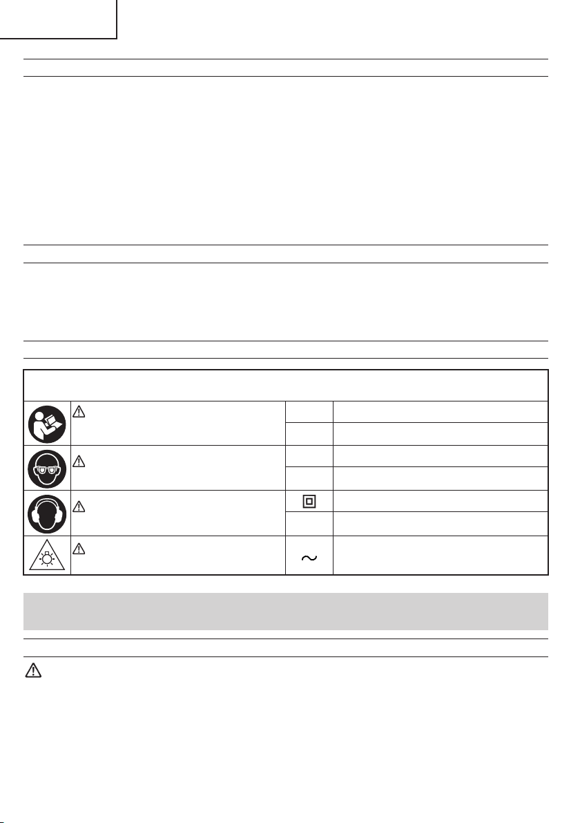
18. Never place your limbs inside of the line next to warning
sign “ ” while the tool is being operated. This may
cause hazardous conditions.
19. Never use abrasive type blades on this saw.
20. Never expose to rain or use in damp locations.
21. Never cut ferrous metals or masonry.
22. Do not replace the LED light with a different type.
23. Do not stand in a line with the saw blade In front of the
machine. Always stand aside of the saw blade. This
protects your body against possible kickback. Keep
hands, fingers and arms away from the rotating saw
blade.
24. Do not cross your arms when operating the tool arm.
WARNING
FOR YOUR OWN SAFETY READ THIS INSTRUCTION
MANUAL BEFORE OPERATING THE COMPOUND
MITER SAW
1. Always wear eye protection when using the compound
miter saw.
2. Always keep hands out of the path of the saw blade.
3. Never operate the saw without the guards in place.
4. Never perform any freehand operation with the
compound miter saw.
5. Never reach around the saw blade.
6. Always turn offtool and wait for saw blade to stop before
moving workpiece or changing settings.
7. Always disconnect power before changing blade or
servicing.
8. Saw blade diameter is 12" (305 mm).
9. No load speed is 4,300 /min.
REPLACEMENT PARTS
When servicing use only identical replacement parts.
Repairs should be conducted only by a metabo HPT
authorized service center.
00BookC12FDHBNANA.indb600BookC12FDHBNANA.indb6 2021/01/2910:32:112021/01/2910:32:11

7
English
USE PROPER EXTENSION CORD
Make sure your extension cord is in good condition. When using an extension cord, be sure to use one heavy enough
to carry the current your product will draw. An undersized cord will cause a drop in line voltage resulting in loss of power
and overheating. Table shows the correct size to use depending on cord length and nameplate ampere rating. If in doubt,
use the next heavier gage. The smaller the gage number, the heavier the cord.
MINIMUM GAGE FOR CORD SETS
Total Length of Cord in Feet (Meter)
0–25
(0–7.6) 26–50
(7.9–15.2) 51–100
(15.5–30.5) 101–150
(30.8–45.7)
Ampere Rating AWG
More
Than Not More
Than
0–6 18 16 16 14
6–10 18 16 14 12
10–12 16 16 14 12
12–16 14 12 Not Recommended
WARNING
Avoid electrical shock hazard. Never use this tool with a damaged or frayed electrical cord or extension
cord.
Inspect all electrical cords regularly. Never use in or near water or in any environment where electric shock
is possible.
DOUBLE INSULATION FOR SAFER OPERATION
To ensure safer operation of this power tool, metabo HPT has adopted a double insulation design. “Double insulation”
means that two physically separated insulation systems have been used to insulate the electrically conductive materials
connected to the power supply from the outer frame handled by the operator. Therefore, either the symbol “ ” or the
words and “Double insulation” appear on the power tool or on the nameplate.
Although this system has no external grounding, you must still follow the normal electrical safety precautions given in this
Instruction Manual, including not using the power tool in wet environments.
To keep the double insulation system effective, follow these precautions:
* Only metabo HPT AUTHORIZED SERVICE CENTER should disassemble or assemble this power tool, and only
genuine metabo HPT replacement parts should be installed.
* Clean the exterior of the power tool only with a soft cloth moistened with soapy water and dry thoroughly.
* Never use solvents, gasoline or thinners on plastic components; otherwise the plastic may dissolve.
SAVE THESE INSTRUCTIONS
AND
MAKE THEM AVAILABLE TO OTHER USERS
AND
OWNERS OF THIS TOOL!
00BookC12FDHBNANA.indb700BookC12FDHBNANA.indb7 2021/01/2910:32:112021/01/2910:32:11

8
English
OPERATION AND MAINTENANCE
NOTE: The information contained in this Instruction Manual is designed to assist you
in the safe operation and maintenance of the power tool. Some illustrations in
this Instruction Manual may show details or attachments that differ from those
on your own power tool.
NAME OF PARTS
MODEL C12FDHB
Locking pin
Saw blade
Carry handle
Motor assembly
Dust bag
Set button
Base
Lock-offbutton
Switch handle
Nameplate
Lower guard
Fence (R)
Indicator
(For miter scale)
Vise assembly
Cover plate
Sub fence (L)
Fence (L)
Motor head
Gear case
Turntable
Positive stop
lock button
Table insert
Indicator
(for right bevel scale)
Sub fence (R)
8 mm knob bolt
Rotation direction
Miter lock handle
Fig. 1
00BookC12FDHBNANA.indb800BookC12FDHBNANA.indb8 2021/01/2910:32:112021/01/2910:32:11

9
English
Indicator
(for left bevel scale)
Carry handle
Miter scale
Miter detent
override button
Vice lock knob
Bevel scale
Dust port
LED light switch
6 mm hex. bar wrench
Trigger switch
Mounting hole
Spindle lock
Angle block
Bevel lock handle
Fig. 2
00BookC12FDHBNANA.indb900BookC12FDHBNANA.indb9 2021/01/2910:32:112021/01/2910:32:11

10
English
SPECIFICATIONS
Item Model C12FDHB
Motor
Type Series commutator motor
Power source Single-phase AC 60Hz
Voltage (Volts) 120
Full-load current (Amp) 15
LED light Yes
Applicable saw
blade
Outside Dia. 12" (305 mm)
Hole Dia. 1" (25.4 mm)
Maximum kerf 7/64" (2.8 mm)
No load speed 4,300 /min
Max. sawing
dimension
Head Turntable Max. sawing dimension
Miter
00
Max. Height
Max. Width
or
Max. Height
Max. Width
2-3/4"
8"
7-3/32"
1-1/16"
(70 mm)
(203 mm)
(180 mm)
(27 mm)
0Left
45°
Max. Height
Max. Width
or
Max. Height
Max. Width
2-3/4"
5-11/16"
4-13/16"
1-3/16"
(70 mm)
(145 mm)
(122 mm)
(30 mm)
0Right
45°
Max. Height
Max. Width
or
Max. Height
Max. Width
2-3/4"
5-11/16"
4-1/32"
19/32"
(70 mm)
(145 mm)
(102 mm)
(15 mm)
0Left
Right 52° Max.Height
Max.Width
2-3/4"
4-29/32"
(70 mm)
(125 mm)
Bevel
Left 45° 0 Max.Height
Max.Width
1-31/32"
8"
(50 mm)
(203 mm)
Right 45° 0 Max.Height
Max.Width
11/16"
8"
(18 mm)
(203 mm)
Compound
Left 45° Left
Right 45° Max.Height
Max.Width
1-3/16"
5-11/16"
(30 mm)
(145 mm)
Right 45° Left
Right 45° Max.Height
Max.Width
11/16"
5-11/16
(18 mm)
(145 mm)
Miter sawing range Left 0°–52° Right 0°–52°
Bevel sawing range Left 0°–48° Right 0°–48°
Compound sawing range Left and Right (Bevel) 0°–45°, Left and Right (Miter) 0°–45°
Net weight 44.1 lbs. (20.0 kg)
Cord 2 Conductor type cable 8.2ft. (2.5 m)
00BookC12FDHBNANA.indb1000BookC12FDHBNANA.indb10 2021/01/2910:32:122021/01/2910:32:12

11
English
ACCESSORIES
WARNING: Accessories for this power tool are mentioned in this Instruction
Manual.
The use of any other attachment or accessory can be dangerous and
could cause injury or mechanical damage.
STANDARD ACCESSORIES
12" (305 mm) TCT Saw blade
(1 piece) (For wood)
(No. of teeth 40 Code No. 377326)
Vise Assembly (1 piece)
For how to use, refer to page 23.
Dust bag (1 piece)
For how to use, refer to page 13.
6 mm hex. bar wrench
Sub fence (L) (1 piece)
For how to use, refer to
page 19.
Fig. 3
OPTIONAL ACCESSORIES...sold separately
Extension holder and Stopper (Code No. 377095)
Crown molding Vise Ass’y (Code No. 339660)
Crown molding Stopper (L) (Code No. 339730)
Crown molding Stopper (R) (Code No. 339731)
NOTE:Accessories are subject to change without any obligation on the part of the
metabo HPT.
00BookC12FDHBNANA.indb1100BookC12FDHBNANA.indb11 2021/01/2910:32:122021/01/2910:32:12

12
English
APPLICATIONS
Wood and aluminum sash.
PREPARATION BEFORE OPERATION
Make the following preparations before operating the power tool:
1. Remove all packing materials attached or connected to the tool before attempting to operate
it.
2. Installation
10-7/32"
(259.75 mm)
9-23/32"
(247 mm)
10-7/32"
(259.75 mm)
9-23/32"
(247 mm)
11/32" (9 mm)
4 holes
13"
(330 mm)
1" (25 mm) thick bench
Work bench 5/16" (8 mm) nut
5/16" (8 mm) boltBase
Fig. 4
Attach the power tool to a level, horizontal work bench in accordance with Fig. 4.
Select 5/16" (8 mm) diameter bolts suitable in length for the thickness of the work bench.
Bolt length should be at least 1-9/16" (40 mm) plus the thickness of the work bench.
For example, use 2-9/16" (65 mm) or larger bolts for a 1" (25 mm) thick work bench.
00BookC12FDHBNANA.indb1200BookC12FDHBNANA.indb12 2021/01/2910:32:132021/01/2910:32:13

13
English
3. Releasing the locking pin
Pull
Locking pin Handle
Fig. 5
When the power tool is prepared for shipping, its
main parts are secured by a locking pin.
Move the handle slightly so that the locking pin
can be disengaged.
NOTE: Lowering the handle slightly will
enable you to disengage the locking
pin more easily and safely.
The lock position of the locking pin is
for carrying and storage only.
4. Installing the sub fence (L), dust bag, extension holder, stopper and vises
(The extension holder and stopper are optional accessories.)
Attach the sub fence (L), dust bag and vise assembly as indicated in Fig. 1 and Fig. 2.
Install the dust bag onto the duct on the miter saw. Fit the
supprot bar of the dust bag and the duct together.
To empty the dust bag, pull out the dust bag assembly
from the duct. Open zipper on underside of bag and empty
into waste container. Check frequently and empty the
dust bag before it gets full.
CAUTION: Empty the dust bag frequently to prevent the duct and the lower
guard from becoming clogged.
Sawdust will accumulate more quickly than normal during bevel
cutting.
WARNING: Do not use this saw to cut and/or sand metals. The hot chips or
sparks may ignite saw dust from the bag material.
(Attach the vise assembly as shown in Fig. 1, Fig. 2 and Fig. 18.)
Fig. 6
Duct
Dust bag
00BookC12FDHBNANA.indb1300BookC12FDHBNANA.indb13 2021/01/2910:32:132021/01/2910:32:13

14
English
BEFORE USING
1. Make sure the power source is appropriate for the tool.
WARNING: Never connect the power tool unless the available AC power
source is of the same voltage as that specified on the nameplate
of the tool.
Never connect this power tool to a DC power source.
2. Make sure the trigger switch is turned OFF.
WARNING: If the power cord is connected to the power source with the
trigger switch turned ON the power tool will start suddenly and
can cause a serious accident.
3. Check the saw blade for visible defects.
Confirm that the saw blade is free of cracks or other visible damage.
4. Confirm that the saw blade is attached securely to the power tool.
Using the supplied 6 mm hex. bar wrench, tighten the 8 mm bolt on the saw blade spindle to
secure the saw blade.
For details, see Fig. 37-a, Fig. 37-b, Fig. 37-c and Fig. 37-d in the section on “SAW BLADE
MOUNTING AND DISMOUNTING”.
5. Check the lower guard for proper operation.
Lower guard is designed to protect the operator from coming
into contact with the saw blade during operation of the tool.
Always check that the lower guard moves smoothly and
covers the saw blade properly.
WARNING: NEVER OPERATE THE POWER TOOL if the lower guard does not
function smoothly.
6. Confirm the position of the spindle lock before using the tool.
After installing the saw blade, confirm that the spindle lock has been returned to the released
position before using the power tool (see Fig. 2).
7. Check the Power Receptacle.
To prevent overheating, accidental stopping or intermittent operation, confirm that the
power cord plug fits properly in the electrical receptacle and does not fall out after it is
inserted. Repair or replace the receptacle if it is faulty.
Fig. 7
Lower guard
00BookC12FDHBNANA.indb1400BookC12FDHBNANA.indb14 2021/01/2910:32:142021/01/2910:32:14

15
English
8. Confirm the tool’s power cord is not damaged.
Repair or replace the power cord if an inspection indicates that it is damaged
9. Eye protection
Always wear eye protection with side shields that meets the requirements of ANSI Standard
Z87.1. Ordinary eyeglasses do not provide adequate protection because they do not contain
impact resistant safety glass.
WARNING: Operating the tool without wearing proper eye protection may
result in serious injury.
10. Electric brake
This tool is equipped with an electric brake which will typically stop the blade within
5 seconds after the trigger switch is released.
Occasionally, there will be a delay in the brake engaging which will result in a longer blade
stopping time. On rare occasions, the brake may not engage at all and the saw blade will
coast to a stop.
If the brake fails to engage frequently, depress and release the trigger switch to turn the
tool on and off4 or 5 times. If the brake still does not engage, have the tool serviced at a
metabo HPT authorized service center.
Always confirm that the saw blade has completely stopped before raising it from the
workpiece.
The brake is not a substitute for a properly functioning lower guard. Check the function of
the lower guard before each use. Serious personal injury may occur if the lower guard does
not move smoothly and cover the blade properly.
WARNING: Please be aware of the reaction of the Motor Head (Fig. 1) when
the brake is activated. Braking causes the Motor Head to jerk
downward and the user should be prepared for this reaction,
especially when the trigger switch is released before the blade is
completely down. Failure to be familiar with, and prepared for, the
operational characteristics of the tool may cause serious injury.
AFTER CONNECTING THE POWER PLUG TO AN APPROPRIATE AC
POWER SOURCE, CHECK THE OPERATION OF THE TOOL AS FOLLOWS:
11. Trial Run
After confirming that no one is standing behind, the power tool start and confirm that no
operating abnormalities exist before attempting a cutting operation.
12. Inspect the rotating stability of the saw blade.
For precise cutting, rotate the saw blade and check for deflection to confirm that the blade
is not noticeably unstable; otherwise vibrations might occur and cause an accident.
00BookC12FDHBNANA.indb1500BookC12FDHBNANA.indb15 2021/01/2910:32:142021/01/2910:32:14

16
English
BEFORE CUTTING
1. Checking the saw blade lower limit position
Check that the saw blade can be lowered
49 mm to 50 mm below the table insert.
When you replace a saw blade with a new
one, adjust the lower limit position so that
the saw blade will not cut the turntable or
complete cutting cannot be done.
To adjust the lower limit position of the saw
blade, follow the procedure (1) indicated
below. (Fig. 8)
Furthermore, when changing the position
of a 6 mm depth adjustment screw that
serves as a lower limit position stopper of
the saw blade.
(1) Turn the 6 mm depth adjustment screw,
change the height where the screw head
and the hinge contacts, and adjust the
lower limit position of the saw blade. The
lower limit position is raised when the 6 mm
depth adjustment screw is turned clockwise.
NOTE: Confirm that the saw blade is adjusted so that it will not cut into the
turntable.
2. Oblique angle
Before the power tool is shipped from the factory, it is adjusted for 0°, right angle, left
33.9° & 45° bevel cutting angle and right 33.9° & 45° bevel cutting angle with the 6 mm set
screw, 6 mm hex. socket screw (A) and 6 mm hex. socket screw (B).
When changing the adjustment, change the height of the 6 mm set screw, 6 mm hex. socket
screw (A) or 6 mm hex. socket screw (B) by turning them. (Fig. 9-a, 9-b)
When changing the height of the 6 mm set screw, using the 3 mm hex key to turn it.
When changing the height of the 6 mm hex. socket screw, using the 5 mm hex key to turn it.
When changing the bevel angle to the right 45°, press the set button on the direction shown
in Fig. 9-b and incline the motor head to the right.
When adjusting the motor head to 0°, always return the set button to its released position.
NOTE: To obtain right bevel angles, press the set button and tilt the saw to the
desired angle.
When obtain left or right 45° bevel cutting angle, do not need to adjust the left & right 33.9° bevel
cutting angle.
Saw blade
Hinge
Turntable
6 mm depth
adjustment screw
Fig. 8
00BookC12FDHBNANA.indb1600BookC12FDHBNANA.indb16 2021/01/2910:32:142021/01/2910:32:14

17
English
Fig. 9-a Fig. 9-b
Angle
block (B)
Angle block (A)
Set button
Press
Angle
block (A)
Angle block (B)
Indicator
(for right bevel scale)
6 mm hex. socket
screw (B)
Indicator
(for left bevel scale)
6 mm hex.
socket screw (A)
6 mm set screw
3. Installing the holders ... (Optional accessory)
Fig. 10
Steel square Base surface
6 mm knob bolt
(Optional accessory)
Holder
(Optional
accessory)
6 mm
wing nut
(Optional
accessory)
Height adjustment bolt 6 mm
(Optional accessory)
The holders help keep longer workpieces
stable and in place during the cutting operation.
(1) As indicated in Fig. 10, use a steel square
for aligning the upper edge of the holders
with the base surface. Loosen the 6 mm
knob bolt. Turn a height adjustment bolt
6 mm, and adjust the height of the holder.
(2) After adjustment, firmly tighten the 6 mm wing nut and fasten the holder with the 6 mm knob
bolt (optional accessory). If the length of height adjustment bolt 6 mm is insufficient, spread
a thin plate beneath. Make sure the end of height adjustment bolt 6 mm does not protrude
from the holder.
00BookC12FDHBNANA.indb1700BookC12FDHBNANA.indb17 2021/01/2910:32:152021/01/2910:32:15

18
English
4. Stopper for precision cutting ... (Stopper and holder are optional accessory)
The stopper facilitates continuous precision
cutting in lengths of 11-27/64" to 18" (290 mm
to 460 mm).
To install the stopper, attach it to the holder
with the 6 mm wing bolt as shown in Fig. 11.
5. Confirmation for use of sub fence (R) (Fig. 12-a)
WARNING: When right bevel angle cutting, loosen the 8 mm knob bolt, then
slide the sub fence (R) outward.
Failure to do so may result in the main body or saw blade coming
into contact with the sub fence (R) and causing injury.
8 mm knob bolt
6 mm screw
Fence (R)
Sub fence (R)
Fig. 12-a
This power tool is equipped with a sub fence
(R).
In the case of direct angle cutting and left bevel
angle cutting, use the sub fence (R). Then, you
can realize stable cutting of the material with a
wide back face.
When right bevel angle cutting, loosen the 8 mm
knob bolt, then slide sub fence (R) outward, as
shown in Fig. 12-a.
If unable to get enough clearance with the
motor head because the bevel angle is too
large, loosen the 6 mm screw and remove the
sub fence (R).
NOTE: When transporting the saw, always
secure the sub fence (R) in the
collapsed position and lock it.
Workpiece
Stopper
(Optional accessory)
Holder
(Optional accessory)
6 mm
wing nut
(Optional
accessory)
Height adjustment bolt 6 mm
(Optional accessory)
6 mm wing bolt
(Optional accessory)
Fig. 11
00BookC12FDHBNANA.indb1800BookC12FDHBNANA.indb18 2021/01/2910:32:152021/01/2910:32:15

19
English
6. Confirmation for use of sub fence (L) (Fig. 12-b)
WARNING: When left bevel angle cutting, loosen the 8 mm knob bolt, then
slide the sub fence (L) outward.
Failure to do so may result in the main body or saw blade coming
into contact with the sub fence (L) and causing injury.
Fig. 12-b
8 mm knob bolt
Sub fence (L)
Fence (L)
6 mm screw This power tool is equipped with a sub fence (L).
In the case of direct angle cutting and right
bevel angle cutting, use the sub fence (L).
Then, you can realize stable cutting of the
material with a wide back face.
When left bevel angle cutting, loosen the 8 mm
knob bolt, then slide the sub fence (L) outward,
as shown in Fig. 12-b.
If unable to get enough clearance with the
motor head because the bevel angle is too
large, loosen the 6 mm screw and remove the
sub fence (L).
NOTE: When transporting the saw, always
secure the sub fence (L) in the
collapsed position and lock it.
7. Bevel angle 33.9°, 45°, 48°
Located deep within both sides of the base are angle block (A) and angle block (B). These
angle blocks are required when sitting up the right and left bevel angles of 33.9°, 45°, or 48°
on the right and left.
(1) Bevel angle of 33.9° (right and left) (Fig. 13-a)
Set up with angle block (A) and angle block (B) stacked, and rotate from B to direction
A. After pulling out the sub fence, loosen the bevel lock handle and tilt the motor head
to place either the 6 mm hex socket screw (A) (when tilted to the left) or the 6 mm hex
socket screw (B) (when tilted to the right) on angle block (B). When the bevel angle is
set, tighten the bevel lock handle to secure the motor head.
(2) Bevel angle of 45° (right and left) (Fig. 13-b)
Rotate angle block (B) on its own from A to direction B. Set angle block (A) on side A.
After pulling out the sub fence, loosen the bevel lock handle and tilt the motor head to
place either the 6 mm hex socket screw (A) (when tilted to the left) or the 6 mm hex
socket screw (B) (when tilted to the right) on angle block (A). When the bevel angle is
set, tighten the bevel lock handle to secure the motor head.
00BookC12FDHBNANA.indb1900BookC12FDHBNANA.indb19 2021/01/2910:32:152021/01/2910:32:15

20
English
(3) Bevel angle of 48° (right and left) (Fig. 13-c)
Rotate both angle block (A) and angle block (B) from A to direction B. After pulling out
the sub fence, loosen the bevel lock handle and tilt the motor head to place either the
6 mm hex socket screw (A) (when tilted to the left) or the 6 mm hex socket screw (B)
(when tilted to the right) on the base surface. When the bevel angle is set, tighten the
bevel lock handle to secure the motor head.
BBBB
AAAA
Bevel pointer
screw
Angle block (B)
6mm Hex.
Socket Screw (A)
Angle block (A)
Fig. 13-a
BBBB
AAAA
Bevel pointer
screw
Angle block (B)
6 mm Hex.
Socket Screw (A)
Angle block (A)
Fig. 13-b
B
A
Bevel pointer
screw
Angle block (B)
Indicator
6 mm Hex.
Socket Screw (A) Angle block (A)
Fig. 13-c
Bevel lock
handle
8. 90° Indicator (For bevel scale) adjustment (Fig. 13-c)
(1) When the blade is exactly 90° (0°) to the table, loosen the bevel pointer screw using a
#2 Phillips screwdriver.
(2) Adjust Indicator to the “0” mark on the bevel scale and retighten the screw.
9. Quick-cam locking lever operation
If miter angles required are NOT one of the nine
positive stops, the turntable can be locked at any
angle between these positive stops by using the
postive stop lock button and miter lock handle.
Unlock the turntable by lifting up the miter lock
handle, grasp the miter lock handle and pressing
down on the postive stop lock button to move the
table to the desired angle, then release the postive
stop lock button. Press down on the miter lock
handle to lock the table in position.
Indicator
Miter scale
Miter lock
handle
Unlock
Lock
Postive stop lock
button
Miter detent
override button Turntable
Fig. 14
00BookC12FDHBNANA.indb2000BookC12FDHBNANA.indb20 2021/01/2910:32:162021/01/2910:32:16
Table of contents
Languages:
Other Metabo HPT Saw manuals

Metabo HPT
Metabo HPT C 7SB3 Troubleshooting guide

Metabo HPT
Metabo HPT C 10FCH2 User manual

Metabo HPT
Metabo HPT C 3610DRA Troubleshooting guide

Metabo HPT
Metabo HPT C 12RSH3 Troubleshooting guide

Metabo HPT
Metabo HPT C 12LDH Troubleshooting guide

Metabo HPT
Metabo HPT C 10FCG Troubleshooting guide

Metabo HPT
Metabo HPT CR 18DB Troubleshooting guide

Metabo HPT
Metabo HPT C 7UR User manual

Metabo HPT
Metabo HPT CR 18DMA Troubleshooting guide

Metabo HPT
Metabo HPT C 10FSH(S) Troubleshooting guide