Festo SDAT-MHS-SV Series User manual

SDAT-MHS-...-SV
Position transmitter
Operating instruc-
tions
8155512
2021-09
[8155514]

Translation of the original instructions

Festo — SDAT-MHS-...-SV — 2021-09
3
Table of contents
1 About this document. . . . . . . . . . . . . . . . . . . . . . . . . . . . . . . . . . . . . . . . . . . . . . . . . . . . . . . . . . . . . 4
1.1 Applicable Documents. . . . . . . . . . . . . . . . . . . . . . . . . . . . . . . . . . . . . . . . . . . . . . . . . . . . . . 4
2 Safety. . . . . . . . . . . . . . . . . . . . . . . . . . . . . . . . . . . . . . . . . . . . . . . . . . . . . . . . . . . . . . . . . . . . . . . . . . 4
2.1 General safety instructions. . . . . . . . . . . . . . . . . . . . . . . . . . . . . . . . . . . . . . . . . . . . . . . . . . . 4
2.2 Intended use. . . . . . . . . . . . . . . . . . . . . . . . . . . . . . . . . . . . . . . . . . . . . . . . . . . . . . . . . . . . . . 4
2.3 Training of qualified personnel. . . . . . . . . . . . . . . . . . . . . . . . . . . . . . . . . . . . . . . . . . . . . . . . 4
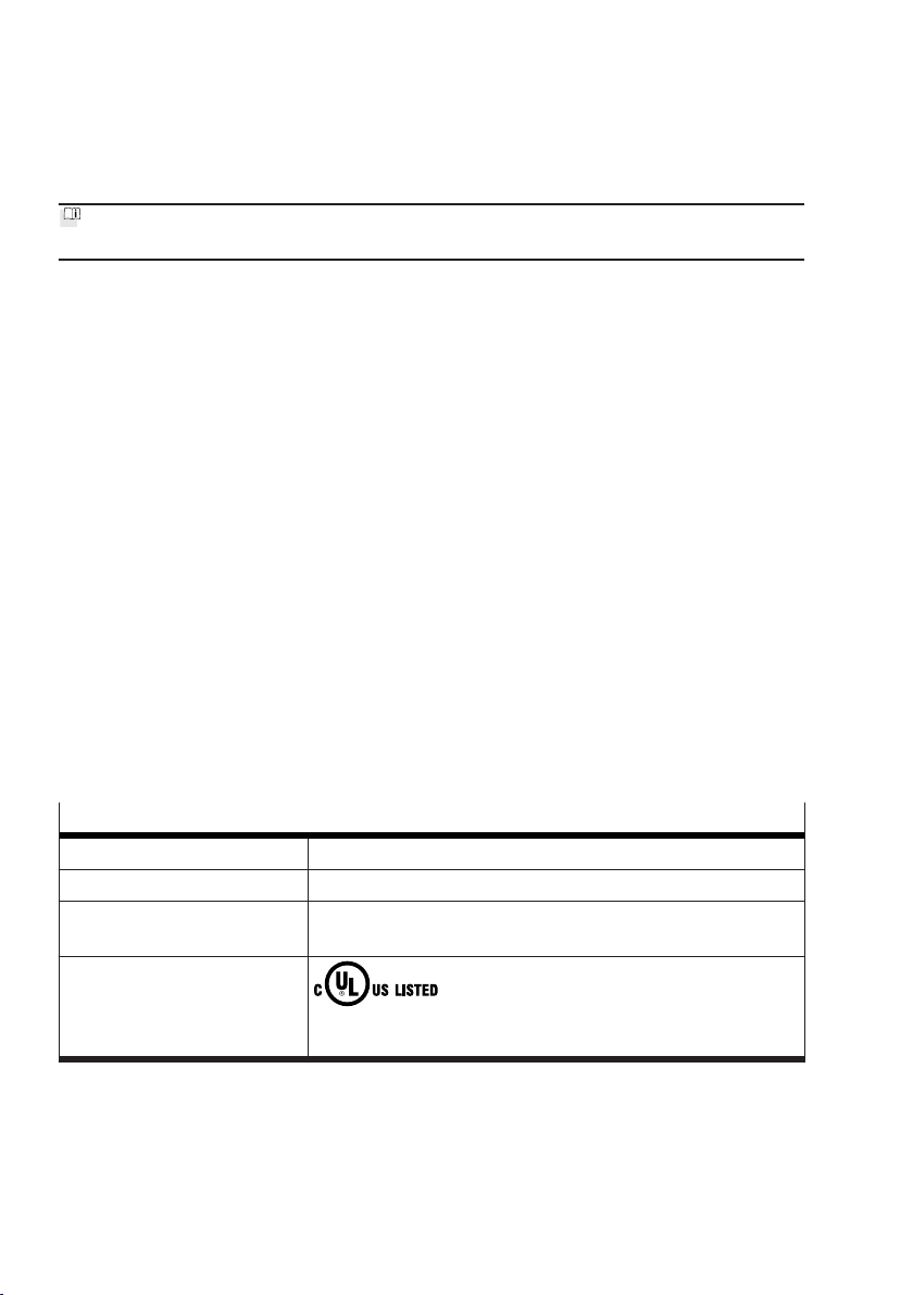
2.4 UL/CSA certification. . . . . . . . . . . . . . . . . . . . . . . . . . . . . . . . . . . . . . . . . . . . . . . . . . . . . . . . 4
3 Additional information. . . . . . . . . . . . . . . . . . . . . . . . . . . . . . . . . . . . . . . . . . . . . . . . . . . . . . . . . . . . 5
4 Product overview. . . . . . . . . . . . . . . . . . . . . . . . . . . . . . . . . . . . . . . . . . . . . . . . . . . . . . . . . . . . . . . . 5
4.1 Design. . . . . . . . . . . . . . . . . . . . . . . . . . . . . . . . . . . . . . . . . . . . . . . . . . . . . . . . . . . . . . . . . . . . 5
4.2 Function. . . . . . . . . . . . . . . . . . . . . . . . . . . . . . . . . . . . . . . . . . . . . . . . . . . . . . . . . . . . . . . . . . 5
4.2.1 Analogue output. . . . . . . . . . . . . . . . . . . . . . . . . . . . . . . . . . . . . . . . . . . . . . . . . . . 6
4.2.2 Switching functions and switching logic. . . . . . . . . . . . . . . . . . . . . . . . . . . . . . . . 8
4.2.3 Switching output operating mode (SIO). . . . . . . . . . . . . . . . . . . . . . . . . . . . . . . 10
4.2.4 IO-Link operating mode. . . . . . . . . . . . . . . . . . . . . . . . . . . . . . . . . . . . . . . . . . . . 10
5Mounting. . . . . . . . . . . . . . . . . . . . . . . . . . . . . . . . . . . . . . . . . . . . . . . . . . . . . . . . . . . . . . . . . . . . . . 11
5.1 Electrical installation. . . . . . . . . . . . . . . . . . . . . . . . . . . . . . . . . . . . . . . . . . . . . . . . . . . . . . . 11
5.2 Mechanical installation. . . . . . . . . . . . . . . . . . . . . . . . . . . . . . . . . . . . . . . . . . . . . . . . . . . . . 12
6Commissioning . . . . . . . . . . . . . . . . . . . . . . . . . . . . . . . . . . . . . . . . . . . . . . . . . . . . . . . . . . . . . . . . 13
6.1 Switch on the position transmitter. . . . . . . . . . . . . . . . . . . . . . . . . . . . . . . . . . . . . . . . . . . . 13
6.2 Setting Set-up mode. . . . . . . . . . . . . . . . . . . . . . . . . . . . . . . . . . . . . . . . . . . . . . . . . . . . . . . 13
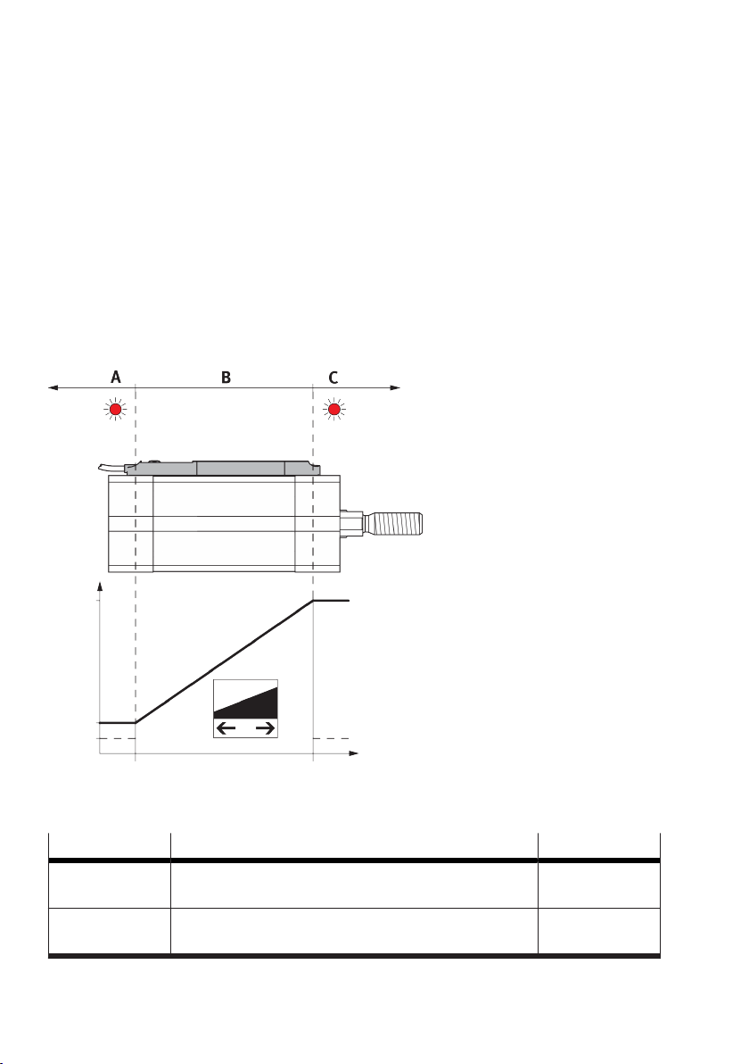
6.3 Scaling analogue signal. . . . . . . . . . . . . . . . . . . . . . . . . . . . . . . . . . . . . . . . . . . . . . . . . . . . 14
6.4 Program switching output. . . . . . . . . . . . . . . . . . . . . . . . . . . . . . . . . . . . . . . . . . . . . . . . . . . 15
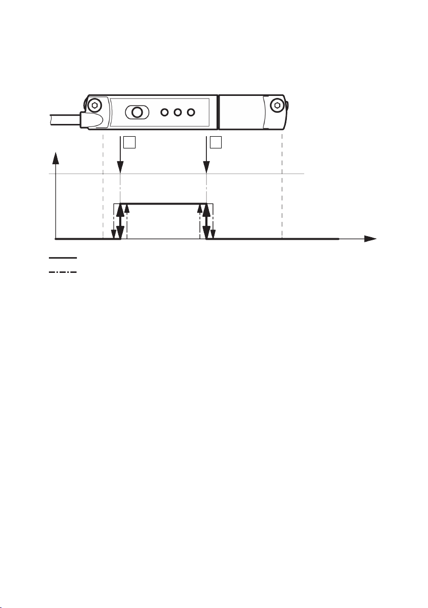
6.4.1 Set window comparator. . . . . . . . . . . . . . . . . . . . . . . . . . . . . . . . . . . . . . . . . . . . 15
6.4.2 Adjusting proximity switch. . . . . . . . . . . . . . . . . . . . . . . . . . . . . . . . . . . . . . . . . . 16
6.4.3 Set hysteresis comparator. . . . . . . . . . . . . . . . . . . . . . . . . . . . . . . . . . . . . . . . . . 17
6.4.4 Inverting switching logic. . . . . . . . . . . . . . . . . . . . . . . . . . . . . . . . . . . . . . . . . . . . 17
6.4.5 Block/unblock operating key. . . . . . . . . . . . . . . . . . . . . . . . . . . . . . . . . . . . . . . . 18
6.4.6 Programming IO-Link output. . . . . . . . . . . . . . . . . . . . . . . . . . . . . . . . . . . . . . . . 18
7Operation. . . . . . . . . . . . . . . . . . . . . . . . . . . . . . . . . . . . . . . . . . . . . . . . . . . . . . . . . . . . . . . . . . . . . 18
7.1 Magnetic direction detection and magnetic direction correction. . . . . . . . . . . . . . . . . . . 18
7.2 LED displays in normal operation. . . . . . . . . . . . . . . . . . . . . . . . . . . . . . . . . . . . . . . . . . . . . 19
7.3 Reset position transmitter to factory setting. . . . . . . . . . . . . . . . . . . . . . . . . . . . . . . . . . . 20
7.4 Analogue output and switching function operation. . . . . . . . . . . . . . . . . . . . . . . . . . . . . . 21
8 Malfunctions. . . . . . . . . . . . . . . . . . . . . . . . . . . . . . . . . . . . . . . . . . . . . . . . . . . . . . . . . . . . . . . . . . . 22
8.1 Diagnostics via LED. . . . . . . . . . . . . . . . . . . . . . . . . . . . . . . . . . . . . . . . . . . . . . . . . . . . . . . . 22
8.2 General malfunctions. . . . . . . . . . . . . . . . . . . . . . . . . . . . . . . . . . . . . . . . . . . . . . . . . . . . . . 22
9Disassembly. . . . . . . . . . . . . . . . . . . . . . . . . . . . . . . . . . . . . . . . . . . . . . . . . . . . . . . . . . . . . . . . . . . 23
10 Technical data. . . . . . . . . . . . . . . . . . . . . . . . . . . . . . . . . . . . . . . . . . . . . . . . . . . . . . . . . . . . . . . . . . 23
10.1 General. . . . . . . . . . . . . . . . . . . . . . . . . . . . . . . . . . . . . . . . . . . . . . . . . . . . . . . . . . . . . . . . . . 23
10.2 IO-Link. . . . . . . . . . . . . . . . . . . . . . . . . . . . . . . . . . . . . . . . . . . . . . . . . . . . . . . . . . . . . . . . . . 25
10.3 I-Port. . . . . . . . . . . . . . . . . . . . . . . . . . . . . . . . . . . . . . . . . . . . . . . . . . . . . . . . . . . . . . . . . . . . 30
10.4 Technical data for UL/CSA certification. . . . . . . . . . . . . . . . . . . . . . . . . . . . . . . . . . . . . . . . 30

4
Festo — SDAT-MHS-...-SV — 2021-09
Safety
1 About this document
1.1 Applicable Documents
All available documents for the product è www.festo.com/sp.
2 Safety
2.1 General safety instructions
–Only use the product in its original condition without unauthorised modifications.
–Only use the product if it is in perfect technical condition.
–The product may generate high frequency interference, which may require interference suppression
measures in residential areas.
2.2 Intended use
The position transmitter is intended for contactless detection of the piston position of magnetic
proximity sensing drives and grippers.
–Use the position transmitter only for suitable Festo drives and grippers.
–Do not place magnetic objects in the immediate vicinity of the position transmitter.
2.3 Training of qualified personnel
Work on the product may only be carried out by qualified personnel who can evaluate the work and
detect dangers. The qualified personnel have skills and experience in dealing with electropneumatic
(open-loop) control technology.
2.4 UL/CSA certification
In combination with the UL inspection mark on the product, the information in this section must also
be observed in order to comply with the certification conditions of Underwriters Laboratories Inc. (UL)
for USA and Canada.
UL approval information
Product category code NRKH, NRKH7
File number E232949
Considered standards UL 60947-1, UL 60947-5-2, CSA C22.2 No. 60947-1, CSA C22.2 No.
60947-5-2
UL mark
Ind. Cont. EQ. (Industrial Control Equipment)
2MD1
Tab. 1: UL/CSA approval information

Festo — SDAT-MHS-...-SV — 2021-09
Product overview
5
–Technical data and environmental conditions may be subject to change in order to comply with
Underwriters Laboratories Inc. (UL) certification requirements for the USA and Canada. è 10.4
Technical data for UL/CSA certification
–Only for connection to a NEC/CEC Class 2 supply.
–The device shall be supplied from an isolating transformer having a secondary listed fuse rated 1 A.
3 Additional information
–Contact the regional Festo contact if you have technical problems è www.festo.com.
–Accessories and spare parts è www.festo.com/catalogue.
4 Product overview
4.1 Design
1
2
3
4
5
6
7
Fig. 1: Design of SDAT-MHS
1
Connecting cable
2
Retaining screws
3
M8 plug, rotatable
4
Red LED: status indicator
5
Green LED: ready status display
6
Yellow LED: switching status display
7
Operating key
4.2 Function
The position transmitter detects the magnetic field of the piston magnet and continuously senses the
piston movement in the sensing range.

6
Festo — SDAT-MHS-...-SV — 2021-09
Product overview
The following output signals are available:
–analogue voltage signal: 0 … 10 V
–programmable switching output: 24 V
–IO-Link communication mode è 4.2.4 IO-Link operating mode
4.2.1 Analogue output
The analogue output provides an output signal 0 … 10 V.
–The output signal is proportional to the path of the piston stroke in the sensing range.
–The output signal can be scaled.
–The direction of increase of the analogue output signal can be inverted.
–The analogue output signal in the switching output operating mode is made available parallel and
independent of the position value output of the switching output.
–The analogue output is switched off in the IO-Link operating mode.
0 mm
0.5 V
1 V
10 V
X mm
Fig. 2: Characteristic curve of the analogue output
X = maximum length of the sensing range
Signal Description Range1)
0 V –IO-Link operation
–Error, e.g. cable break, parameter error
–
0.5 V –Piston is outside the sensing range after switching on
the operating voltage
A, C

Festo — SDAT-MHS-...-SV — 2021-09
Product overview
7
Signal Description Range1)
1 V –The piston has left the sensing range in the direction of
the falling output current
A
> 1 V … < 10 V –Piston is within the sensing range B
10 V –Piston has left the sensing range in the direction of the
rising output voltage
C
1) Range Fig. 2, range A and C: red LED on
Tab. 2: Output signal of the analogue output
The analogue output is switched off during active IO-Link communication. The output voltage is 0 V.
Scaling of the analogue signal
The analogue output signal is assigned by default to the complete sensing range. If only a part of the
sensing range is to be used, the analogue value output can be scaled to the sensing range in use. The
resolution and the repetition accuracy are not improved by scaling.
10 V
1 V
0.5 V
0 mm
60 mm
120 mm
160 mm
Analogue signal scaled
Analogue signal not scaled
1 2
Fig. 3: Scaling of the analogue signal using the SDAT-MHS-M160 as an example
1Teach-in point 1 2Teach-in point 2

8
Festo — SDAT-MHS-...-SV — 2021-09
Product overview
4.2.2 Switching functions and switching logic
4.2.2.1 Window comparator
IN
OUT
Switching travel
Hysteresis
1 2
Fig. 4: Window comparator
1Teach-in point 1 2Teach-in point 2
Teach-in points 1 and 2 are linked to the window comparator function.
–The position of the teach points determines the window width.
–Hysteresis is not selectable or preset.

Festo — SDAT-MHS-...-SV — 2021-09
Product overview
9
4.2.2.2 Proximity switch
OUT
IN
Hysteresis
Switching travel
1
Fig. 5: Proximity switch
1Teach-in point
The proximity switch function consists of a switching path and hysteresis. Hysteresis serves to sup-
press switching signals in the event of fluctuations around the switching point.
–The teach-in value is the centre of the switching path.
–The switching path and the hysteresis are not adjustable. Values for the switching path and the
hysteresis are stored that correspond to a typical electronic proximity switch on a typical drive.

10
Festo — SDAT-MHS-...-SV — 2021-09
Product overview
4.2.2.3 Hysteresis comparator
Switching travel
OUT
IN
2 1
Fig. 6: Hysteresis comparator
1Teach-in point 1 2Teach-in point 2
Teach-in points 1 and 2 are linked to the hysteresis comparator function.
–Teach-in point 1 (ON) is the switch-on point, teach-in point 2 (OFF) is the reset point.
–Teach-in point 2 establishes the size of the hysteresis.
4.2.2.4 Switching logic
The switching logic normally open (NO) is set as the default. If the switching logic normally closed (NC)
is selected, the function of the switching output is inverted.
4.2.3 Switching output operating mode (SIO)
If the IO-Link/switching output is operated as a switching output, only 1 binary channel can be
programmed. The switching output operating mode must be programmed actively via the Set-up mode
è 6.2 Setting Set-up mode.
–The window comparator, the proximity switch or the hysteresis comparator function are program-
mable.
–The normally closed (NC) or the normally open (NO) switching logic can be selected.
–Programming via the IO-Link protocol (channel BDC1) or the operating key on the device.
–Display switching output ON: the yellow LED is on.
–Output signal 24 V DC (PNP).
Even if the analogue output has been scaled, the switching output can still be programmed over the
entire sensing range.
4.2.4 IO-Link operating mode
Programmed switching signals and the continuous position values (digitally coded analogue values)
are transferred in the IO-Link operating mode.

Festo — SDAT-MHS-...-SV — 2021-09
Mounting
11
2.
–Proximity switches, window comparators or hysteresis comparators can be programmed separately
on 4 binary channels.
–The continuous position values are always transferred parallel and independently of the position
value output of the binary channels.
–Every channel can be set to be normally closed (NC) or normally open (NO).
–The data transfer is serially and digitally coded in the IO-Link protocol.
–Process data: 12 bit for position data and 4 bit for binary channels è 10 Technical data.
–Unshielded standard cables up to 20 m in length can be used.
–The device description file IODD for every device length è www.festo.com/sp.
–Parameters and function in accordance with Smart-Sensor profile.
–The optional block parameterisation and Data Storage functions are supported.
–IO-Link operation display: the green LED flashes.
–The direction of the process data values (PDV) can be inverted.
The PDVs are minimum (standard) or maximum (inverted) and end of the sensor cable.
5 Mounting
5.1 Electrical installation
WARNING
Risk of injury due to electric shock.
• For the electrical power supply, use only PELV circuits in accordance with IEC 60204-1/EN 60204-1
(Protective Extra-Low Voltage, PELV).
• Observe the general requirements of IEC 60204-1/EN 60204-1 for PELV circuits.
•Only use voltage sources that ensure a reliable electric separation from the mains network in
accordance with IEC 60204-1/EN 60204-1.
1. Switch off the operating voltage.
Connect the M8 plug to the connecting cable of the higher-order controller.
–Max. tightening torque for the union nut of the plug: 0.3 Nm.
Fig. 7: Circuit diagram
Pin Allocation Plug
1 Operating voltage +24 V DC M8x1, 4-pin
2 Analogue output 0 … 10 V
3 0 V
4 IO-Link/switching output (C/Q line)
Tab. 3: Pin allocation of plug connection

12
Festo — SDAT-MHS-...-SV — 2021-09
Mounting
4.
5.2 Mechanical installation
You can mount the MS6-SV-E in any desired position.
1
2
3
Fig. 8: Mechanical installation
1
Hexagon socket spanner
2
Retaining screw
3
T-slot
1. Push the position transmitter into the T-slot of the drive.
2. Move the piston to an end position of the application.
3. Push the position transmitter in the direction of the piston until the red LED goes out.
Hand-tighten the retaining screw.
–Max. tightening torque: 0.5 Nm
–Tool: internal hexagon socket key (size 1.5 mm).

Festo — SDAT-MHS-...-SV — 2021-09
Commissioning
13
6 Commissioning
6.1 Switch on the position transmitter
• Switch on the operating voltage.
ÄThe LEDs light depending on the position of the piston è Tab. 5 LED displays in normal
operation.
ÄThe position transmitter is ready for operation.
Parameters Factory setting
Switching function None
Switching logic Normally open contact (N/O)
Scaling Total sensing range
Tab. 4: Factory settings of the position transmitter
6.2 Setting Set-up mode
•Press the operating key 3 times within 3 s.
ÄSet-up mode active: the green LED and the yellow LED flash simultaneously.
If, after entering the Set-up mode, programming is not completed within 60 s, the position transmitter
automatically switches to the operating mode.

14
Festo — SDAT-MHS-...-SV — 2021-09
Commissioning
6.3 Scaling analogue signal
10 V
1 V
0.5 V
0 mm
60 mm
120 mm
160 mm
Analogue signal scaled
Analogue signal not scaled
1 2
Fig. 9: Scaling the analogue signal using the SDAT-MHS-M160 as an example
1Teach point 1 2Teach point 2
Requirement: the piston is in the sensing range (red LED off).
1. Switch to the Set-up mode .
2. Press the operating key 5 times in succession.
ÄThe analogue output can be scaled: the green LED flashes 5 times in quick succession within
2 s.
3. Move the piston to the starting point of the sensing range.
4. Press the operating key.
ÄTeach point 1 is defined: the starting point of the sensing range at 0 V.
ÄThe green LED continues flashing, the yellow LED flashes at 1 Hz.
5. Move the piston to the end point of the sensing range.
6. Press the operating key.
ÄTeach point 2 is defined: the end point of the sensing range at 10 V.
ÄThe position transmitter switches to the operating mode.
To invert the direction of increase of the analogue signal: set teach point 2 (10 V) on the cylinder axis
before teach point 1 (0 V).

Festo — SDAT-MHS-...-SV — 2021-09
Commissioning
15
6.4 Program switching output
6.4.1 Set window comparator
IN
OUT
Switching travel
Hysteresis
1 2
Fig. 10: Window comparator
1Teach point 1 2Teach point 2
Requirement: the piston is in the sensing range (red LED off).
1. Switch to the Set-up mode è 6.2 Setting Set-up mode.
2. Press the operating key once.
ÄThe green LED flashes once within 2 s.
3. Move the piston to the first switching point (teach point 1).
4. Press the operating key once.
ÄSwitching point 1 is set.
ÄThe green LED continues flashing, the yellow LED flashes at 1 Hz.
5. Move the piston to the second switching point (teach point 2).
6. Press the operating key once.
ÄSwitching point 2 is set.
ÄThe position transmitter switches to the operating mode.

16
Festo — SDAT-MHS-...-SV — 2021-09
Commissioning
6.4.2 Adjusting proximity switch
OUT
IN
Hysteresis
Switching travel
1
Fig. 11: Proximity switch
1Teach point
Requirement: the piston is in the sensing range (red LED off).
1. Switch to the Set-up mode è 6.2 Setting Set-up mode.
2. Press the operating key twice.
ÄThe green LED flashes 2 times quickly within 2 s.
3. Move the piston to the first switching point (teach point 1).
4. Press the operating key once.
ÄSwitching point 1 is set.
ÄThe position transmitter switches to the operating mode.

Festo — SDAT-MHS-...-SV — 2021-09
Commissioning
17
6.4.3 Set hysteresis comparator
Switching travel
OUT
IN
2 1
Fig. 12: Set hysteresis comparator
1Teach point 1 2Teach point 2
Requirement: the piston is in the sensing range (red LED off).
1. Switch to the Set-up mode è 6.2 Setting Set-up mode.
2. Press the operating key 3 times.
ÄThe green LED flashes 3 times quickly within 2 s.
3. Move the piston to the switch-on point (teach point 1).
4. Press the operating key once.
Ä The switch-on point is established.
ÄThe green LED continues flashing, the yellow LED flashes at 1 Hz.
5. Move the piston to the reset point (teach point 2).
6. Press the operating key once.
ÄThe reset point is established.
ÄThe position transmitter switches to the operating mode.
6.4.4 Inverting switching logic
The switching logic can be inverted from N/C to N/O and vice versa.
1. Switch to the Set-up mode è 6.2 Setting Set-up mode.
2. Press the operating key 4 times.
ÄThe green LED flashes 4 times quickly within 2 s.
ÄThe yellow LED lights: the currently set switching logic is N/C.
The yellow LED is off: the currently set switching logic is N/O.
3. Press the operating key once.
Ä The switching logic is inverted.
The position transmitter switches to the operating mode.

18
Festo — SDAT-MHS-...-SV — 2021-09
Operation
6.4.5 Block/unblock operating key
In IO-Link mode, the operating key is always blocked.
In the switching output operating mode, the operating key is unlocked by default. However, in the
IO-Link mode the operating key can be blocked for the switching output mode:
1. Start IO-Link communication.
2. Select key lock for switching output operating mode in the IO-Link parameter menu:
–Device access block
–Local user interface block
LED display with blocked operating key
–If the operating key is pressed, the green LED flashes for 3 s at 3 Hz.
–The yellow LED displays the current status of the switching output.
–The red LED only lights if the piston is outside the sensing range.
6.4.6 Programming IO-Link output
The IO-Link function cannot be set with the operating keys on the device. All settings for set-up,
commissioning and parameterisation are made in the higher-level controller of the IO-Link master.
1. Upload the IODD device description file belonging to the device to the interpreter of the IO-Link
master.
2. Connect the IO-Link/switching output to the IO-Link master.
3. Program the device è Operating instructions for the IO-Link master.
An error during commissioning is displayed on the user interface of the IO-Link master and the
programming option is blocked.
7Operation
7.1 Magnetic direction detection and magnetic direction correction
During initial commissioning or after a reset to factory settings, the position transmitter outputs the
signals directly using the currently detected magnetic direction.
The magnetic direction detection and, with it, the signal curve are corrected during continuing opera-
tion in the following cases:
–The position transmitter was placed in operation in a position in which it was not possible to detect
a correct magnetic direction, e.g. due to ferromagnetic materials near the sensor or within the drive
or gripper.
–The position transmitter was rotated 180° in the slot after the magnetic direction was detected as
stable.
Brief error signals may be detected at the sensor output if automatic correction of the magnetic
direction detection is required è 8.2 General malfunctions.

Festo — SDAT-MHS-...-SV — 2021-09
Operation
19
7.2 LED displays in normal operation
LED display Description
Yellow Green Red
Ready for operation:
–Analogue output function or switching output operating mode.
–Piston within the sensing range.
Green LED: on
Red LED: off
Ready for operation:
–IO-Link operating mode.
Green LED: flashing at 1 Hz
Ready for operation:
–Switching output switched.
–Piston in the range of a programmed function.
Yellow LED: on
Green LED: on
Red LED: off
Status indicator:
–Operating key blocked.
Green LED: flashes 3 s at
3 Hz when the operating key is
pressed
Status indicator:
–Piston outside the sensing range.
Red LED: on
Tab. 5: LED displays in normal operation
Query configuration
The currently set configuration can be queried in the Set-up mode.
1. Switch to the Set-up mode è 6.2 Setting Set-up mode.
2. Press the operating key 6 times.
ÄThe yellow, green and red LEDs flash cyclically according to the current configuration
è Tab. 6 Status indicators in the Set-up mode.
3. To terminate the query, press the operating key once.
ÄThe position transmitter switches to the operating mode.
If the operating key is not pressed, the device automatically switches to the operating mode after 60 s.
LED display Description
Green Function
No display Deactivated
flashes once Window comparator

20
Festo — SDAT-MHS-...-SV — 2021-09
Operation
LED display Description
2 flashes Proximity switch function
3 flashes Hysteresis comparator
Yellow Switching logic
flashes once Normally closed (N/C contact)
2 flashes Normally open contact (N/O)
Red Scaling
flashes once User-configured
2 flashes Total sensing range
Tab. 6: Status indicators in the Set-up mode
7.3 Reset position transmitter to factory setting
1. Switch to the Set-up mode è 6.2 Setting Set-up mode.
2. Press the operating key 10 times.
ÄThe yellow, green and red LEDs flash at 1 Hz.
3. Press the operating key.
ÄThe position transmitter is reset to the factory settings.
ÄThe position transmitter switches to the operating mode.
Other manuals for SDAT-MHS-SV Series
1
Table of contents
Other Festo Transmitter manuals

Festo
Festo SDAT-MHS SA Series Reference guide

Festo
Festo SPTW Series User manual

Festo
Festo SDAS-MHS User manual

Festo
Festo SDAT-MHS-SV Series Reference guide

Festo
Festo SDAT-MHS User manual

Festo
Festo SDAS-MHS User manual

Festo
Festo SMAT-8M User manual

Festo
Festo SDAS-MHS User manual

Festo
Festo SDAT-MHS User manual
Popular Transmitter manuals by other brands

Invisible systems
Invisible systems QCO168 installation manual

Garrett
Garrett Z-Lynk Wireless System user guide

Becker
Becker Centronic SunWindControl SWC241 Assembly and operating instructions

Siemens
Siemens sitrans lr 460 operating instructions

Microwave Radio
Microwave Radio Transmitter Operator's guide

SWIT
SWIT CW-S300 user manual