MetaLife CADILLAC Technical Document

Review 02/18/2021
Equipment Manual
CADILLAC

2
THIS MANUAL CONTAINS ESSENTIAL INFORMATION FOR THE USE OF YOUR EQUIPMENT.
PLEASE READ IT CAREFULLY BEFORE STARTING INSTALLATION AND OPERATION. PRESERVE IT
AND KEEP IT FOR FUTURE CONSULTATIONS
Equipment manual
CADILLAC
Throughout this manual, this symbol on the left will indicate extremely
important information that must be read, understood and strictly followed.

4
TABLE OF CONTENTS
Product presentation ........................................................5
Technical specifications ....................................................6
Packaging content ........................................................... 7
Instruction manual ........................................................... 10
Components .................................................................... 10
Preparation for Assembly ................................................ 12
Detailed Assembly .......................................................... 13
User manual .................................................................... 20
Uses and Settings ........................................................... 20
Maintenance and Safety ................................................. 25
Warranty Term ............................................................... 28

5
PRODUCT PRESENTATION
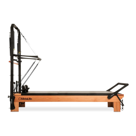
The Cadillac, also known as a trapeze table, is one of the most versatile and effective
equipment ever developed for the Pilates method. In studios and gyms, it is considered a
key item.
This robust equipment offers a wide range of applications for all users, as well as being
very easy to adapt. The Cadillac has been designed to benefit from patients in
physiotherapy to athletes. Using the Cadillac, you add over 200 exercises to your Pilates
repertoire, challenging your body in new and different action plans.
Metalife's Cadillac is designed to give the user maximum comfort and safety. It has two
sliding supports that allow great versatility in the use of its springs with different resistances.
Its dense upholstery is ideal for exercises in sitting, standing or lying positions.
Its stainless steel and carbon steel structure supports the most diverse movements involved
in the Pilates method, enabling more efficiency and safety in the practice of exercises.
Built with Lyptus hardwood, from 100% sustainable and renewable sources, Metalife's
Cadillac allows its disassembly for easier transportation. It's Metalife caring about the
quality of its equipment and the future of the environment.

6
TECHNICAL SPECIFICATIONS
DIMENSION
CADILLAC
LOW
CADILLAC
Note: The weight of the
equipment may change due
to the density variation of
the raw material used in its
manufacture.
MAXIMUM WEIGHT
SUPPORTED

7
PACKAGING CONTENT
PACKAGING CONTENT
1
CD BASE
2
CD FOOT SET 2 (2X)
3
CD FOOT SET 1 (2X)
4
ROLL-DOWN BAR
5
CD UPPER BEAM (2X)
6
CD SLIDING BEARING COLUMN (2X)
7
CD GRAB BAR COLUMN SET 2
8
CD GRAB BAR COLUMN SET 1
9
CD STRINGER (2X)
10
CD MANUAL KIT
11
CD VERTICAL SLIDING BEARING SET
12
CD HORIZONTAL SLIDING BEARING SET
13
SELF-RETRACTING TR/CD/WU GRAB BAR FRAME SET
14
PACKAGING OF ACCESSORIES

8
PACKAGING CONTENT

9
PACKAGING CONTENT
PACKAGING OF ACCESSORIES
1
BLACK SPRING (2X)
2
WHITE SPRING (2X)
3
YELLOW SPRING (2X)
4
RED SPRING (2X)
5
BLUE SPRING (4X)
6
INT HEX SCREW PN ZP 3/8X3/4 (20X)
7
FLAT WASHER ZB 1.9X7X1 7 MM (1/4) (6X)
8
INT HEX SCREW CL ZP 1 /4X1 1 /2 (6X)
9
7X70MM SINGLE LOCK CARABINER (28X)
10
SHORT HEXAGONAL ALLEN KEY 5/16
11
SHORT HEXAGONAL ALLEN KEY 7/32
12
SHORT HEXAGONAL ALLEN KEY 3/16
13
17MM COMBINATION WRENCH
14
FUZZY HANDLE (2X)
15
THIGH-FOOT HANDLE (2X)
16
HEX NUT AT ZB M10 (8X)
17
FLAT WASHER ZB 2X1 0.5X21 MM (M10) (16X)
18
INT HEX SCREW CL ZB M10X70MM (8X)
19
HEADLESS INT HEX SCREW WITH KNURLED CONCAVE TIP 3/8”X1/4” (28X)
20
SAFETY LOCK CLIP (1X)
21
SUPPORT STRAP
22
SAFETY STRAP
23
HAND HANDLE (2X)
24
ABDOMEN STRAP
25
COLUMN SUPPORT 1 (2X)
26
COLUMN SUPPORT 2 (2X)

10
INSTALLATION MANUAL
For your convenience, Metalife has a Network of Authorized Technicians qualified to install
your equipment (an installation fee will be charged for this service).
Such installation does not comprise site preparation services, which are the responsibility of
the client.
If you prefer, you can assemble your equipment yourself, as long as you follow the
instructions in this manual step by step.
Components

11
CONTENT
1
CD BASE 201 2
2
TR/CD/WU 201 2 SUPPORT BAR FRAME SET
3
SLIDING BEARING COLUMN CD
4
CD STRINGER
5
SUPPORT BAR COLUMN 1 CD 201 2
6
SUPPORT BAR COLUMN SET 2 CD 201 2
7
FEET SET 1 CD 201 2
8
FEET SET 2 CD 201 2
9
INT HEX SCREW CL ZP 1/4X1 ¾ (6X)
10
INT HEX SCREW CL ZB M10X70MM (8X)
11
INT HEX SCREW ON ZO 3/8X3/4
12
HEX NUT AT ZB M10 (8X)
13
INT HEX SCREW CL ZB M10X70MM (8X)
14
INT HEX SCREW PN ZP 3/8X3/4
15
HEX NUT AT ZB M10 (8X)
16
FLAT WASHER ZB 2X1 0.5X21 MM (M10) (16X)
17
FLAT WASHER ZB 1.9X7X1 7MM (1/4) (6X)
18
CD 201 2 HORIZONTAL SLIDING BEARING SET (1X)
19
CD 201 2 VERTICAL SLIDING BEARING SET (1X)
20
7X70MM SINGLE LOCK CARABINER (14X)
21
CD EST SET 201 1 (1X)
22
CD TRAPEZE 201 2 (1X)
23
SPRING COVER (2X)
24
ROLL-DOWN BAR (1X)
25
SAFETY STRAP (1X)
26
ABDOMEN STRAP 201 2 (1X)
27
FUZZY HANDLE
28
SUPPORT STRAP
29
HAND HANDLE
30
17MM COMBINATION WRENCH
31
SHORT ALLEN KEY 5/16
32
SHORT ALLEN KEY 7/32
33
SHORT ALLEN KEY 3/16
34
BLUE SPRING (2X)
35
BLACK SPRING (2X)
36
YELLOW SPRING (2X)
37
WHITE SPRING (2X)
38
RED SPRING (2X)
39
SAFETY LOCK CLIP (X1)

12
PREPARATION FOR ASSEMBLY
The CADILLAC must be installed and used in an environment conducive to Pilates practice.
The following characteristics must be respected in the equipment installation area:
• proper leveling and floor stability;
• low humidity;
• protection against sunlight.
TOOLS AND FASTENERS FOR ASSEMBLY
For your comfort, Metalife provides all the tools and
fasteners needed to assemble your equipment.
Keep them for future maintenance or component
replacement.
Make sure you have them at hand and
identify them on the side and in the table
on page 6 before starting assembly.
During assembly, the guidelines contained in this manual must be properly
followed. The equipment is subject to damage during this process, so be
careful when dealing with components and tools.
Damage caused by failure to comply with the instructions in this manual is
the responsibility of the client.
If you have any questions or difficulties, please contact Metalife Technical
Assistance.
Following the instructions contained in
this manual, it is estimated that the
complete assembly of your Cadillac will
take 60 minutes.
02 people are needed
to assemble the
equipment.

13
DETAILED ASSEMBLY
SETTING THE FEET
Start assembly by placing the feet along the base frame of your Cadillac equipment.
FITTING THE FEET
Fit the feet along the base frame observing the correct engagement position of the dowels.
Press until you get a fit between the feet and the base frame. After fitting the feet, turn the
equipment over, being careful not to hold it by the feet. Ask someone else for help in this
procedure.

14
SETTING THE FEET
Attach the feet to the base frame using the set
of fasteners listed below in the following order:
INT HEX SCREW CL ZB M10X70MM, FLAT
WASHER ZB 2X10.5X21MM (M10) (2x, one
on each side of the wooden structure) and
HEX NUT AT ZB M10. Use the SHORT
HEXAGONAL ALLEN KEYS 5/16 AND 17MM
COMBINATION WRENCH for this procedure.
DO NOT FULLY TIGHTEN THE FEET IN ORDER TO FIT THE FLANGES.
INSTALLING COLUMN SUPPORTS
There are different brackets for the left and
right side of the apparatus. Align the bracket
holes with the holes existing in the feet and
frame. Fix them using the INT HEX SCREW
PN ZP 3/8X3/4. Use the 7/32 short hexagonal
Allen key in this procedure.
POSITIONING THE COLUMNS
There are two models of columns: sliding
bearing columns and support bar columns.
The columns of the support bar have left and
right sides.

15
The support bar columns must be fitted to the
side supports.
Align the columns so that the support bar
holes face the center of the apparatus.
MAKE SURE THE TOP HOLES ARE
DIAGONALLY FACING INWARDS.
MAKE SURE THE TOP HOLES ARE
DIAGONALLY FACING INWARDS.
Fit the sliding bearing columns, so that the
holes for the adjustment of the sliding bearing
are facing the outside of the apparatus.
If the holes do not line up, invert the position
of the column by placing the other end inside
the support.

16
PRE-ASSEMBLY OF THE
VERTICAL SLIDING BRACKET
Insert the “t”-shaped pieces into the beam of the vertical
sliding bar, observing the bushing to fit the tube, as
shown in the figure. A light tap with your hand is enough
to fully fit the piece. Immediately after, install the
retractable knobs, threading them into the "t" pieces:
VERTICAL SLIDER
INSTALLATION OF THE SUPPORT
Insert the sliding bearing into the columns, with
the knobs facing outward. Make sure they are
the columns of the sliding bearing.
TO PLACE THE VERTICAL SLIDING BEAM,
PULL THE TWO LOCK-OUT KNOBS AND
MOVE THE BAR.
THE TWO LOCK-OUT KNOBS MUST BE
CLOSED TO USE THE VERTICAL SLIDING
BAR.
CLOSED
Locked Position
OPEN
Locked Position
In the closed position, the knob operates to lock the
Vertical Sliding Set. To unlock it, just pull the knob
and turn it 90"; in this process, your Vertical Sliding
Set is ready to change to the desired height.
To lock your Vertical Sliding Set again, just return
the knob to its initial position, release it and make
sure that it has locked.
CAUTION WHEN PULLING
THE KNOB, AS
EXCESSIVE FORCE MAY
DAMAGE THE KNOB AND
ITS LOCKING AND
UNLOCKING OPERATION.
Lock-Out Knob
Vertical Sliding Beam
[illegible]
[illegible]

17
HORIZONTAL SLIDING BAR PRE-ASSEMBLY
Male Knob 3P
Horizontal Sliding Beam
Igus Bushing
Metal Bearing
Insert the “t”-shaped pieces into the beam of the
vertical sliding bar, observing the bushing to fit the
tube, as shown in the figure.
A light tap with your hand is enough to fully fit the
piece. Immediately after, install the male threaded
knobs, threading them into the "t" pieces.
STRUCTURE ASSEMBLY
Position the stringers so that they fit into the
horizontal sliding bracket. Leave the sliding bracket
with the eyebolts facing down.
BOTH KNOBS MUST BE TIGHT TO USE THE
HORIZONTAL SLIDING BAR.
Fit the upper rail / beam sets to the ends of the
stringers and ensure the eyebolts are facing
downwards.
Fix the upper beam sets to the stringers using
INT HEX SCREWS AB 3/8 X 3/4, ensuring
that it passed through the hole in the stringer,
and the SICAB SCREW 3/8 X 1/4 and tighten
both with the ALLEN WRENCH 7/32. Repeat
this procedure on all four sides of the frame.

18
INSTALLING AND FIXING THE UPPER STRUCTURE
Fit the upper structure to the columns,
inserting their vertical tubes in them to
continue their fixation. For fixing, use SICAB
SCREW 3/8 X 114.
THREAD THE SCREWS WITHOUT
TIGHTENING. THE FINAL
TIGHTENING WILL BE MADE
LATER.
INSTALLATION OF THE SUPPORT BAR
Insert the movable pin of the push bar
frame at the desired height. Push the
frame against the column to retract the
movable pin to the point where you can
align the fixed pin with the equivalent hole
in the opposite column. Once the pin is
aligned, just release the frame, and it will
fit the columns.
TEST THE VERTICAL SLIDING BRACKET (PAG. 14). FINAL TIGHTEN THE
UPPER FRAME BOLTS USING A 7/32 SHORT ALLEN WRENCH.

19
FIXING THE COLUMNS
Insert the four HEADLESS INT HEX
SCREW WITH KNURLED CONCAVE TIP
ZP 3/8X1/4 into each support column.
They must be centered on the support.
Subsequently, with the 3/16 SHORT
HEXAGONAL ALLEN WRENCH, do the
final tighten of the screws, making their
heads close to the walls of the supports.
UPHOLSTERY ASSEMBLY
Position the upholstery over the
Cadillac's wooden base. Underneath
the Cadillac, secure using SCREW 51
CL ZP 1/4x13/4 and FLAT WASHER
1.9X7X17MM (1/4). Tighten up with the
SHORT HEXAGONAL ALLEN
WRENCH 3/16.

20
USER MANUAL
USES AND SETTINGS
SUPPORT BAR
The support bar has 3 (three) height
settings, which can be adjusted
according to the size of the person or
the difficulty of the exercise. Engage
the movable pin side first. Push the
frame against the column to retract the
movable pin to the point where you can
align the fixed pin with the equivalent
hole in the opposite column. Once the
pin is aligned, just release the frame,
and it will fit the columns.
To adjust the height of the support bar,
push the frame against the column to
retract the movable pin to the point
where you can remove it from the metal
frame. Position the bar at the new
desired height, align with the opposite
equivalent hole and release the frame.
When using the support bar, the safety
strap must always be used. Make sure
the carabiner is fully closed and in good
condition.
BE CAREFUL WITH THE SUPPORT BAR, AS IT IS ONE OF THE MOVING PARTS OF THE EQUIPMENT THAT WILL
BE TENSIONED BY SPRINGS. IMPROPER USE MAY CAUSE ACCIDENTS. USE THE SAFETY STRAP. A TRAINED
PROFESSIONAL MUST KEEP ONE HAND ON THE BAR AT ALL TIMES TO PREVENT INJURY.

21
USE OF SAFETY LOCK CLIP
We do not recommend the use of cross
springs on the push bar. However, if it is
impossible to avoid such practice, the
use of the safety lock clip will be
necessary.
Next to the push bar, installed on the
fixed pin, there is a safety lock clip.
In addition to it, another spare is
provided, which can be found in the
accessories package.
To install the safety lock clip, just
remove it from the fixed pin and install
it on the movable pin, as shown in the
image on the opposite side. This
application must be done with the
push frame installed on the Cadillac,
at the height selected for the exercise.
Since, to change the position of the
frame (unlock), it will be necessary to
return the clip to its initial position, on
the fixed pin.
ANY ACCIDENT CAUSED BY THE USE OF CROSSED (NON-PARALLEL) SPRING(S), AS NOT
RECOMMENDED IN THIS USER MANUAL, IS THE SOLE RESPONSIBILITY OF THE INSTRUCTOR.
Table of contents
Other MetaLife Fitness Equipment manuals
Popular Fitness Equipment manuals by other brands

G-FITNESS
G-FITNESS AIR ROWER user manual

CAPITAL SPORTS
CAPITAL SPORTS Dominate Edition 10028796 manual

Martin System
Martin System TT4FK user guide

CIRCLE FITNESS
CIRCLE FITNESS E7 owner's manual

G-FITNESS
G-FITNESS TZ-6017 user manual

Accelerated Care Plus
Accelerated Care Plus OMNISTIM FX2 CYCLE/WALK user manual


