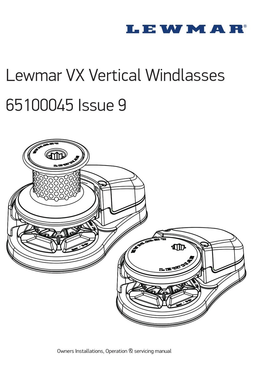
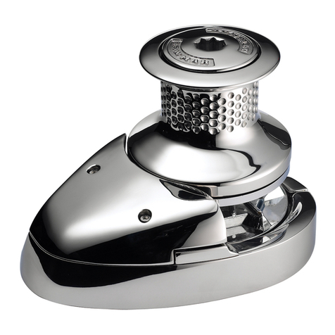
Lewmar V8 Quick start guide

Lewmar V8/ V9/ V10/ V12 Windlass
66300094 Issue 6
Owners Installations, Operation & servicing manual
GB

2
GB
Introduction
Dear Customer,
Thank you for choosing Lewmar. Lewmar products are world renowned for their quality, technical innovation and
proven performance. With a Lewmar product you will be provided with many years of outstanding service.
Product support
Lewmar products are supported by a worldwide network of distributors and Authorised Service Representatives.
If you encounter any difficulties with this product, please contact your national distributor, or your local Lewmar
dealer. Details are available at: www.lewmar.com
CE Approvals
For CE approval certificates contact Lewmar.
Important information about this manual
Throughout this manual, you will see safety and product damage warnings. You must follow these warnings
carefully to avoid possible injury or damage.
The type of warnings, what they look like, and how they are used in this manual are explained as follows:.
WARNING!
This is a warning against anything which may
cause injury to people if the warning is ignored.
You are informed about what you must or must
not do in order to reduce the risk of injury to
yourself and others.
This manual forms part of the product and
MUST BE kept with boat documents.
SAFETY SYMBOL
When you see the safety symbol it
means: “Do not...”; “Do not do this”; or
“Do not let this happen”.
To the best of our knowledge, the information in this manual was correct when it went to press. However, Lew-
mar cannot accept liability for any inaccuracies or omissions it may contain. In addition, our policy of continuous
product improvement may change specifications without notice. As a result, Lewmar cannot accept liability for
any differences between the product and the manual.

Lewmar V8/V9/V10/V12 Vertical Windlass ref 66300094 Iss.6 | 3
1. Safety Notice
IMPORTANT: Read these notes before continuing.
1.1 Windlass general
Classification Societies and Lewmar require that a vessel at anchor must have its chain/rode held by a chain
stopper or equivalent strong point at all times
At all times it is the responsibility of the boat operator to ensure that the anchor and rode are properly stowed
for the prevailing sea conditions. This is particularly important with high-speed powerboats, because an anchor
accidentally deploying while under way can cause considerable damage. An anchor windlass is mounted in the
most exposed position on a vessel and is thus subject to severe atmospheric attack resulting in a possibility of
corrosion in excess of that experienced with most other items of deck equipment. As the windlass may only be
used infrequently, the risk of corrosion is further increased. It is essential that the windlass is regularly
examined, operated and given any necessary maintenance.
Please ensure that you thoroughly understand the operation and safety requirements of the windlass before
commencing the installation. Only persons who are completely familiar with the controls and those who have
been fully made aware of the correct use of the windlass should be allowed to use it. If there is any doubt of how
to install or operate this unit please seek advice from a suitably qualified engineer.
• Windlasses used incorrectly could cause harm to equipment or crew.
• Windlasses should be used with care and treated with respect.
• Boating, like many other activities can be hazardous. Even the correct selection, maintenance and use of
proper equipment cannot eliminate the potential for danger, serious injury or death.
• Lewmar windlasses are designed and supplied for anchor control in marine applications and are not to be used
in conjunction with any other use.
• Keep limbs, fingers, clothing and hair clear of windlass, rode and anchor during operation. Severe bodily harm
could result.
• Ensure there are no swimmers or divers nearby when dropping anchor.
• Windlasses must not be used as the sole means of securing the anchor to the bow fitting especially under
storm conditions. Anchors should be independently secured to prevent accidental release.
• Classification Societies require that a vessel lying at anchor must have its anchor rope/chain secured to a
chain stopper or other suitable independent strong point.
• A windlass should never be used as a mooring bollard, the anchor rode MUST be secured to a mooring cleat,
chain stopper or other designated strong point. Using the windlass to secure the rode will damage the
windlass.
• Do not use windlass for ANY purpose other than deployment and recovery of anchor.
• Do not wrap chain around a capstan barrel or drum where fitted.
• The circuit breaker in this product must never be deactivated or otherwise bypassed, it is intended to protect
the motor and cables from overheating and damage.
• Always switch off this windlass at the circuit breaker/isolator when not in use.
• It is the unavoidable responsibility of the owner, master or other responsible party to assess the risk of any
operation on the vessel.
• Windlass must not be operated whilst under the influence of alcohol or drugs.
1.2 Fitting
• This equipment must be installed and operated in accordance with the instructions contained in this manual.
Failure to do so could result in poor product performance, personal injury and/or damage to your boat.
• Consult the boat manufacturer if you have any doubt about the strength or suitability of the mounting
location.
1.3 Electrical
• Make sure that the boat’s battery power supply has been switched off before starting the installation.
• This product requires installation by a suitably qualified electrical engineer.
WARNING!
4
GB
2. Anchoring Procedures
IMPORTANT: Read these notes before continuing.
The following guidelines are designed to assist crews in the correct usage of Lewmar anchoring equipment when
deploying or retrieving the anchor.
Ensure the crew are fully trained in proper anchoring techniques to safely anchor the boat.
Refer to the Lewmar Owners’ Manual for safe operation of your windlass.
2.1 Windlass Holding Load
The holding load of a windlass is calculated to be 1,5 x Max. Pull. If a higher load than this is exerted back
through the windlass, breakages may occur.
2.2 Deploying Anchor
Apply the windlass band brake to prevent the gypsy from rotating. Remove any devils claw device used for
securing the anchor, and ensure that the chain stopper is also released.
Raise the windlass drum / top nut to disengage the drive dogs. Ensuring that it is safe to do so, gradually release
the brake to allow the anchor & anchor chain to free fall, keeping its descent under control using the brake to
prevent it running away. Continue until the required amount of chain has been deployed to offer the ideal scope
for the conditions.
2.3 Apply the Chain Stopper
Engage the chain stopper paddle ensuring that it is fully registered between adjoining links.
2.4 Setting Anchor
Once the anchor load has been transferred to the chain stopper, it is now possible to use the boats’ engine
power to set the anchor. If more scope is required, release the chain stopper and pay out more chain, ensur-
ing that the chain stopper has once again been applied before allowing more load to be pulled. Once anchored,
secure the anchor rode using the chain stopper. Tighten down the windlass drum / top nut to re-engage the drive
dogs in preparation for raisingthe anchor.
2.5 Breaking & Retrieving Anchor
Release the chain stopper.
The windlass must not be used for pulling the boat to the anchor or breaking out the anchor if it
is fouled.
When retrieving the anchor rode, always motor towards the anchor. If the anchor is fouled, re-apply the chain
stopper and use the boat’s engine to break the anchor loose.
2.6 Stowing Anchor
As the anchor breaks water, use short pulses on the control to bring the anchor up to its docking position,
watching carefully to ensure that it is correctly orientated to prevent damage. Once the anchor has been fully
docked, apply the devils claw or other device to secure the anchor, before releasing any tension on the windlass.

Lewmar V8/V9/V10/V12 Vertical Windlass ref 66300094 Iss.6 | 5
360˚
3.1-1 3.1-2
3.1-3
30°
3.1-4
3. Installation
3.1 Above deck preparation
NOTE: Lewmar recommends V8/9/10/12 windlasses are specified and installed by competent marine engineers.
IMPORTANT: Plan location carefully making sure that the operator can monitor the anchor recovery and rode
stowage and allow for the following:
All models:
IMPORTANT: The positioning of the motor/gearbox must be checked prior to cutting for deck/hull and bulkhead
clearance.
• Confirm L/H or R/H deck unit chain alignment.
• If possible, select a flat area of deck. To take up any camber or sheer a suitable pad will be required.
1. Make an accurate drilling template using the product dimensions from Section 8 and position in line with
anchor chain centre line.
2. Check space available under deck for electric/hydraulic motor unit and cable runs.
3. With the handle inserted, check that the drum can rotate through 360 degrees.
• Check the deck surrounding the windlass to ensure there is space for attachment and operating movement of
band brake handle.
• Positioning of remote handwheel if fitted.
Model V9 /10 / 12
4. Standard brake operation position shown, orientation can be rotated in 30 degree increments to optimise
brake position.

6
Max 76 mm
74 Nm
3.2-1
3.2-3
3.2-2
74 Nm
3.2-4
GB
3.2 Model V8 fitting windlass
• Drill 13mm diameter stud holes.
• Drill 150mm and 115mm diameter holes.
• With a sandwich deck construction it is important to seal the exposed surfaces.
1. Fit studs to windlass base and tighten to 74Nm.
2. Measure deck depth plus clamp plate and the 2 nuts and add 5mm. Trim studs to length, if required.
Maximum deck thickness 76mm (3”)
3. Apply a bead of suitable sealant/bedding compound and mount the windlass through the deck.
4. Fit windlass to deck and tighten locknuts to 74Nm.
NOTE: If using silicone or other rubbery type sealant, it is advisable to allow curing of the sealant before final
tightening of the mounting nuts.
DO NOT use a permanent
adhesive/sealant, eg. 5200.

Lewmar V8/V9/V10/V12 Vertical Windlass ref 66300094 Iss.6 | 7
45°
3.3-1
3.3-43.3-3
3.3-2
43 Nm
3.3 Model V8 under deck fitting
1. There are 4 positions available for electric motor/gearbox.
2. Minimum depth under deck required for electric motor/gearbox and hydraulic motor unit, see §8
3. Lightly coat the sha of the windlass with grease. Ensure the drive key is in place and, selecting the most
suitable of the 4 positions, slide the motor/gearbox into position.
4. Assemble the bolts and washers and secure with Loctite® threadlock to 43Nm.

8
119 Nm
30°
3.4-1
3.4-3
119 Nm
3.4-4
Max 150mm
3.4-2
GB
3.4 Model V9 fitting windlass
• NOTE: Lewmar recommends V9 windlasses are specified and
installed by competent marine engineers.
• Using template drill 6 x 15mm diameter bolt holes.
• Cut 178mm and 140mm diameter holes.
• With a sandwich deck construction it is important to seal the exposed surfaces.
1. Fit studs to windlass base and tighten to 119Nm.
2. Measure deck depth plus deck backing plate and the 2 nuts and add 5mm. Trim studs to length, if required.
Maximum deck thickness 150mm.
• Apply a bead of suitable sealant/bedding compound and mount the windlass through the deck.
3. Select the operating position for the band brake and insert bolts.
4. Assemble the deck backing plate and M14 nuts. Use Loctite® threadlock and torque to 119Nm.
Secure with M14 Nyloc nut.
NOTE: If using silicone or other rubbery type sealant, it is advisable to allow curing of the sealant before fi nal
tightening of the mounting nuts.
WARNING! Extremely heavy,
use mechanical lift aid.
DO NOT use a permanent
adhesive/sealant, eg. 5200.

Lewmar V8/V9/V10/V12 Vertical Windlass ref 66300094 Iss.6 | 9
43 Nm
74 Nm
3.5-1
3.5-4
3.5-3
3.5-2
3.5 Model V9 under deck fitting
1. The motor/gearbox is bolted directly to the base via an adaptor. There are various positions available.
NOTE: Motor/gearbox must not obstruct the chain fall hole.
2. Minimum depth under deck required for electric motor/gearbox and hydraulic motor unit, see §8.
3. Fit the adaptor to the base of the windlass with 8 - M10x55 bolts and M10 spring washers secure to 43Nm.
4. Lightly coat the splined drive sha of the windlass with grease.
• Electric/hydraulic motor/gearbox
Gently slide the splined end of the motor/gearbox coupling onto the spline of the windlass drive sha and
secure with grub screw. Ensure drive key is on the coupling. Selecting the most suitable position, slide the
motor/gearbox in to place until its face meets with the adaptor plate. Secure with 8 - M12x50 bolts and M12
spring washers to 74Nm.
• Hydraulic drive with brake
Proceed as above except this unit does not require a motor/gearbox coupling.
NOTE: Additional support is required for the electric motor/gearbox using the mounting support under the motor.
WARNING! Extremely heavy,
use mechanical lift aid.

10
30°
3.6-1
3.6-3
3.6-2
Max 200mm
183 Nm
GB
3.6 Model V10/12 fitting windlass
• NOTE: Lewmar recommends V10/12 windlasses are specified and
installed by competent marine engineers.
• Using template drill 6 x 17mm diameter bolt holes.
• Cut 260mm and 120mm diameter holes.
• With a sandwich deck construction it is important to seal the exposed surfaces.
1. Measure deck depth plus the washer and 2 nuts then add 5mm. Select M16 bolts of suitable length
(not supplied by Lewmar). Maximum deck thickness 200mm.
• Apply a bead of suitable sealant/bedding compound and mount the windlass through the deck.
2. Select the operating position for the band brake and insert bolts.
3. Assemble the washer and M16 nut first and secure with Loctite® threadlock to 183 Nm and then secure with
M16 Nyloc nut.
NOTE: If using silicone or other rubbery type sealant, it is advisable to allow curing of the sealant before final
tightening of the mounting nuts.
WARNING! Extremely heavy,
use mechanical lift aid.
DO NOT use a permanent
adhesive/sealant, eg. 5200.

Lewmar V8/V9/V10/V12 Vertical Windlass ref 66300094 Iss.6 | 11
3.7-1
3.7-4
3.7-3
3.7-2
43 Nm
3.7 Model V10 & V12 under deck fitting
1. The motor/gearbox is bolted directly to the base via a down tube. There are various positions available.
NOTE: Motor/gearbox must not obstruct the chain fall hole.
2. Minimum depth under deck required for electric motor/gearbox and hydraulic motor unit, see §8.
3. Lightly coat the splined sha of the windlass with grease. Selecting the most suitable position, slide the mo-
tor/gearbox in to place.
4. Assemble the bolts and washers and secure with Loctite® threadlock to 43Nm.
NOTE: Additional support is required for the electric motor/gearbox using the mounting support under the motor.
WARNING! Extremely heavy,
use mechanical lift aid.

12
3.8-23.8-1
3.8-3
3.9-1
GB
3.8 Model V8 remote brake cable installation (optional)
Illustrations based on 68000876
1. Insert one end of the brake cable into band brake
pins on deck unit ensuring that both parts are fully
located into recesses of pins as shown.
2. Rotate hand wheel anti-clockwise until the slide
has fully wound back as shown.
Insert other end of cable.
3. Rotate handwheel clockwise to move slide up into
the housing body ensuring that cable end is fully
located in slide recess.
• Keep rotating handwheel until the outer sheath of
cable is fully located into end of housing body and
slack cable is taken up.
• Firmly secure to deck with M10 / ⅜” CSK Head
bolts.
3.9 Model V9/10/12 remote brake installation (optional)
1. Select suitable position of band brake ring for brake
wheel position.
• Insert brake wheel UJ connecter shaft in handle
socket of deck unit ensuring that both parts are
fully located.
• Hand tighten shaft until brake is applied, then back
off 3 full turns.
• Once position of band brake and operating handle is
established drill deck and secure using (20mm V9 /
24mm V10-12) stud through deck.

Lewmar V8/V9/V10/V12 Vertical Windlass ref 66300094 Iss.6 | 13
2.5 KW 24V DC USING 66000894 200 AMP MCB
CABLE SIZING FOR LENGTH OF CABLE RUN
0 - 23 m 0 - 75 ft 23- 34 m 75 - 95 ft 34 - 47 m 95 - 119 ft 47 - 64 m 119 - 151 ft
35 mm² 2 AWG 50 mm² 1 AWG 70 mm² 0 AWG 95 mm² 2/0 AWG
3.5 KW 24 VDC USING 66000895 250 AMP MCB
CABLE SIZING FOR LENGTH OF CABLE RUN
0 - 20 m 0 - 76 ft 20- 27 m 76 - 96 ft 27 - 38 m 96 - 122 ft 38 - 52 m 122 -154 ft 52 - 66 m 154 - 193ft
35 mm² 1 AWG 50 mm² 0 AWG 70 mm² 2/0 AWG 95 mm² 3/0 AWG 120 mm² 4/0 AWG
4.1 Electric cable selection
Lewmar recommends the installer source and install cable that meets the requirements of the standards and
regulations relevant to the installation and codes of practice. The cable table gives recommended cable sizes
based on total length of cable required, from the battery, following the route of the cables.
Windlass performance is directly related to cable size and length.
Voltage drop over the complete wiring run must not exceed 10%.
4. Electrical wiring
4.2 Wiring
Plan the installation to suit the controls and give the operator a full view of the windlass. The wiring system
should be of the fully insulated type, which avoids possible electrolytic corrosion problems. We recommend the
use of type III stranded, tinned copper wire with copper crimp terminals. Most modern installations are negative
return (negative ground) but polarity should be checked.
Overload protection, in the form of the circuit breaker/fuse supplied, must be built into the windlass wiring
circuit.
DO NOT confuse cable length
with the length of the vessel
NOTE:
• The circuit breaker should be positioned close to the battery in a dry, readily accessible place.
• The breaker must be manually reset should an overload occur that causes it to trip to the off position.
• If you are not sure you understand these guidelines, seek professional help. Ensure that the installation
complies with USCG, ABYC, NMMA or other local regulations.
WARNING!
4.3 Control switch installation
Follow the mounting instructions supplied with the switch.
NOTE: In a multi station installation all switches must be wired in a parallel circuit.
4.4 V8/9/10/12 AC electric wiring installation
AC electric wiring information for the V8/9/10/12 will be published on a separate addition that can be found on
Lewmar website www.lewmar.com

14
Thermal
Switch
Reed Switch Sensor
for Chain Counter
(If fitted)
Control Box
(24 V - 68000130)
Circuit Breaker
2.5 kW - 200 A - 68000894
3.5 kW - 250 A - 68000895
Battery
Isolator
Battery
24 VDC
Control Box
(24 V - 18000237)
Contactor
(24 V - 68000321)
Contactor
(24 V - 68000319)
Electric Deck Switches
Rocker
Switches
Electric Remote
Control
Thermal
Switch
Fuse
3 A
V8 3.5 kW - 24 VDC
V8 2.5 kW - 24 VDC V8 2.5 kW - 24 VDC
V8 3.5 kW - 24 VDC
4
5
64
5
6
4
5
6
4
5
6
4
5
6
1
2
3
1
2
3
1
2
3
1
2
3
1
2
3
Wireless Remote
Control
Part No. 68000967
UP DOWN
UP
DOWN
ON
GB
4.5 V8 Wiring diagram
V8 windlass models
Switch wire thickness: 1.5 mm² (16 AWG)

Lewmar V8/V9/V10/V12 Vertical Windlass ref 66300094 Iss.6 | 15
DR
Fig 5.1
5. Hydraulic System
5.1 Installation
Windlass unit should be connected to a hydraulic powerpack with directional control valve installed to control
the windlass movement.
Fig 5.1 shows typical hydraulic circuit for a windlass with the Hi-Power or Standard motor/gearbox.
5.2 V8 Hydraulic motor/gearbox
The hydraulic motor/gearbox consists of a high torque hydraulic motor fitted to a 90 degree gearbox or or an
in-line gearbox.
Refer to section 5.5 for flows and pressures information.
The motor gearboxes are not self sustaining. A dual Pilot Operated Check Valve (POCV) must be installed in the
system to temporarily sustain any load. The POCV can be line mounted (as shown in Fig 5.1) or modular type if
for example a CETOP 3 directional valve is being used.
NOTE: To permanently sustain a load a Chain Stopper must be used.
5.3 V9/10/12 Hydraulic motor/gearbox
The hydraulic motor/gearbox consists
of a high torque hydraulic motor fitted
to an in line gearbox with brake.
Refer to section 5.7 for flows and pressures information.
The motor gearbox is self sustaining.
5.4 Hose types
For reliable operation and safety it is essential
to use reinforced braid hose for connecting to
the motor A and B ports which conforms to
SAE100R2A or DIN 20 021 Part 2.
The recommended hose sizes are:
• Up to 30 l/min + ½” (13mm) bore diameter.
• Up to 40 l/min + ⅝” (16mm) bore diameter.
• Up to 57 l/min + ¾” (19mm) bore diameter.
• Ref: 3.78 litres = 1 US gallon
4.54 litres = 1 Imperial gallon

16
Min 85 mm
Min 85 mm
Standard Motor/gearbox Fig 5.6
Hi-Power Motor/gearbox Fig 5.5
GB
5.5 Model V8 motor ports & drain - Hi-Power motor/gearbox
The Lewmar hydraulic motor ports are:
A & B ports ¾” BSP.
Drain port (only Hi-Power motor/gearbox) is ¼” BSP.
• The location of the ports for the Hi-Power motor/gearbox is shown in Fig 5.5. A drain line is required for the
motor/gearbox.
• The minimum bore diameter of the drain line required is 6mm.
Safe working pressure: 10 bar.
• Tubing material: Oil compatible semi-rigid plastic tube braided hose or steel pipe.
5.6 Model V8 Motor ports - Standard motor/gearbox
The location of the ports for the Standard motor/gearbox is shown in Fig 5.6 (no drain connection).
5.7 Model V9/10/12 motor ports & drain
The Lewmar hydraulic motor ports are:
A & B ports ½” BSP.
Drain port is ¼”BSP.
1. Hydraulic installation schematic:
• V9 - 5:1 Hydraulic gearbox (with brake) 300cc motor.
• V9 - 7:1 Hydraulic gearbox 230cc motor.
• V10 - 5:1 Hydraulic gearbox (with brake) 500cc motor.
• V12 - 13:1 Hydraulic gearbox (with brake) 250cc motor.
2. The location of the ports for the motor/gearbox is shown in Fig 5.7-2.
• A drain line is required on V9/10/12 motor/gearbox with brake.
• The minimum bore diameter of the drain line required is 10mm (⅜”).
Safe working pressure: 10 bar.
• Tubing material: Oil compatible semi-rigid plastic tube braided hose or steel pipe.

Lewmar V8/V9/V10/V12 Vertical Windlass ref 66300094 Iss.6 | 17
Fig 5.7-1

18
Case Drain
1/4” BSP
Case Drain
1/4” BSP
A & B Ports
3/4” BSP
V9/10 V12
A & B Ports
1/2” BSP
V9
A & B Ports
3/4” BSP
Fig 5.7-2
GB

Lewmar V8/V9/V10/V12 Vertical Windlass ref 66300094 Iss.6 | 19
6.2-1 6.2-2
ON
6.3-3 6.3-4
6. Operation
6.1 Powered drive overview
The main sha, driven by the motor/gearbox, drives directly with the capstan. The gypsy can either be powered
by the capstan or be free running. The gypsy is powered by engaging the dog drive teeth of the capstan to those
of the gypsy.
6.2 Capstan dog drive release
1. Tighten the band brake with a Lewmar winch handle to secure the gypsy.
2. Place a Lewmar winch handle into the top nut and turn anti-clockwise raising the capstan until the dog drive
is fully disengaged. Remove the handle.
6.3 Capstan dog drive engagement / permanent drive
3. Place a Lewmar winch handle into the top nut and lower the capstan down onto the gypsy until resistance is
felt. Back wind one quarter of a turn. Remove handle
4. Press the UP/DOWN switch and the dog drive will spring down into positive engagement.
• Tighten down the top nut securely if required.
• Once the dog drive has been fully engaged, stop power operation and release the band brake before powered
operation is continued.
• Remove handle.
WARNING! Always remove
handle when not in use.

20
3
ON
6.4-1 6.5-2
ON
6.6-3 6.6-4
GB
6.4 Power up/down
NOTE: Ensure that the band brake is released and that the dog drive is fully engaged.
1. Press the deck switch, remote control or toggle switch (anchor up/down).
Note: As anchor approaches the vessel use careful adjustments of controls to avoid damaging vessel
6.5 Braked anchor free-fall
NOTE: Ensure that the dog drive is fully released and band brake is fully tightened.
2. Using a Lewmar winch handle carefully release the brake to allow the gypsy to run free. The descent of the
chain can be controlled and stopped by tightening the band brake.
6.6 Independent capstan/warping operation
NOTE: Ensure that the dog drive is fully released and band brake is fully tightened.
3. For temporary use of capstan, ensure chain is adequately secured to an independent strong point.
4. Wrap at least 3 coils of rope, loosely around capstan drum.
• Press the UP button to power the capstan and apply tension to rope gently.
• If warping speed is too fast, ease tension with rope.
6.7 Servicing schedule
Regularly:
• Wash down the windlass using fresh water.
• Examine all electrical connections for corrosion,
clean and lightly grease.
Annually:
• Check electric cables for damage.
Repair/renew as required.
• Strip the above deck components, clean and lightly
grease.
DO NOT wrap chain
around the capstan drum
This manual suits for next models
3
Table of contents
Other Lewmar Marine Equipment manuals

Lewmar
Lewmar 140 User manual

Lewmar
Lewmar AutoAnchor 560 User manual

Lewmar
Lewmar CPX0- 500W User manual

Lewmar
Lewmar 300 SVTAH User manual

Lewmar
Lewmar AutoAnchor 150 User manual

Lewmar
Lewmar V1 Quick start guide

Lewmar
Lewmar Pro Series Quick start guide

Lewmar
Lewmar AA550 User manual

Lewmar
Lewmar VX Series User manual

Lewmar
Lewmar AutoAnchor 550 User manual