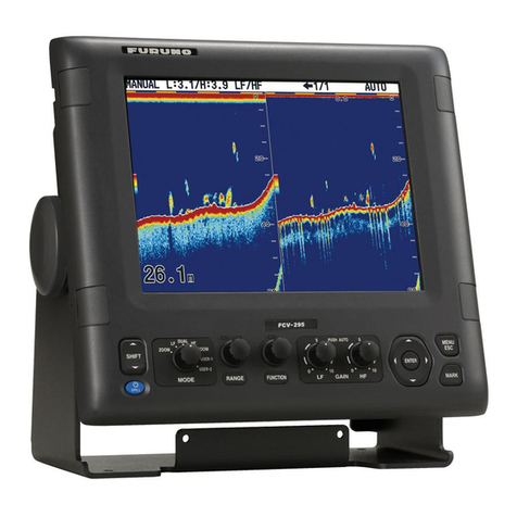
Furuno FSV-25 MARK-2 User manual

www.furuno.com
A
ll brand and product names are trademarks, registered trademarks or service marks of their respective holders.
Installation Manual
COLOR SCANNING SONAR
Model
FSV-25 MARK-2/FSV-25S MARK-2
SAFETY INSTRUCTIONS ........................i
SYSTEM CONFIGURATION ..................iii
EQUIPMENT LISTS................................iv
1. HOW TO INSTALL THE SYSTEM ..1-1
1.1 Hull Unit ..............................................1-1
1.2 Processor Unit ....................................1-6
1.3 Control Unit .........................................1-7
1.4 Transceiver Unit................................1-12
1.5 Power Supply Unit ............................1-14
1.6 Junction Box .....................................1-15
1.7 Raise/Lower Control Box ..................1-16
1.8 Control Box Extension Box ...............1-17
1.9 Installing to an Existing Retraction
Tank..................................................1-18
1.10 Sub Control Unit (Option)..................1-22
2. WIRING............................................2-1
2.1 How to Connect the Units ...................2-1
2.2 Processor Unit ....................................2-4
2.3 Control Unit .......................................2-10
2.4 Transceiver Unit................................2-11
2.5 Junction Box .....................................2-14
2.6 Raise/Lower Control Box ..................2-15
2.7 Power Supply Unit ............................2-16
2.8 Control Box Extension Box ...............2-17
3. ADJUSTMENT AND CHECKS........3-1
3.1 How to Set the Language ...................3-1
3.2 How to Register the Transducer
Position ...............................................3-2
3.3 Hull Unit Checks .................................3-3
3.4 How to Adjust the Heading .................3-9
3.5 How to Configure the Own Ship Mark...3-
10
3.6 How to Select Monitor Resolution.....3-10
3.7 How to Set Up a Secondary Monitor.3-11
3.8 System Menu ....................................3-11
3.9 Connection with Maxsea TZ
Professional ......................................3-13
APPX. 1 JIS CABLE GUIDE............AP-1
APPX. 2 FRP/ALUMINUM
RETRACTION TANK
INSTALLATION ................AP-2
APPX. 3 INSTALLATION CHECK
LIST ...................................AP-5
PACKING LIST(S)............................... A-1
OUTLINE DRAWING(S)...................... D-1
INTERCONNECTION DIAGRAM(S) ... S-1

The paper used in this manual
is elemental chlorine free.
・FURUNO Authorized Distributor/Dealer
9 52 Ashihara cho,
Nishinomiya, 662 8580, JAPAN
A
:
JAN
2022
.
Printed in Japan
All rights reserved.
Pub. No.
IME-13690-A
(
REFU
)
FSV-25-MARK-2
0 0 0 1 9 9 2 4 5 1 1

i
SAFETY INSTRUCTIONS
Indicates a potentially hazardous situation which, if not avoided, may
result in minor or moderate injury.
Indicates a potentially hazardous situation which, if not avoided, will
result in death or serious injury.
Indicates a potentially hazardous situation which, if not avoided,
could result in death or serious injury.
DANGER
WARNING
CAUTION
Warning, Caution Prohibitive Action Mandatory Action
The installer must read the safety instructions before attempting to install the equipment.
WARNING
Turn off the power at the mains
switchboard before beginning the
installation.
Fire, electrical shock or serious injury can
result if the power is left on or is applied
while the equipment is being installed.
Do not install the equipment where it
may get wet from rain or water splash.
Water can cause fire or electrical shock, or
damage the equipment.
DANGER
Keep away from raise/lower shaft in
hull unit when it is moving.
Gears will cause serious injury. In case of
an emergency, press the EMERGENCY
STOP button to stop the raising or
lowering of the transducer.
Confirm that there is no person below
the transducer before raising or
lowering the transducer.
WARNING
Do not open the equipment unless
totally familiar with electrical circuits
and service manual.
High voltage exists inside the equipment,
and a residual charge remains in
capacitors several minutes after the power
is turned off. Improper handling can result
in electrical shock.
Be sure no water leaks in at the hull
unit.
Water leakage can sink the vessel. Also
confirm that the transducer will not loosen
by ship's vibration. The installer of the
equipment is solely responsible for the
proper installation of the equipment.
FURUNO will assume no responsibility for
any damage associated with improper
installation.
If a steel tank is installed on a wooden
or FRP vessel, take appropriate
measures to prevent electrolytic
corrosion.
Electrolytic corrosion can damage the hull.
Check the motor brake and drive shaft
brake are functioning correctly before
raising/lowering the transducer
manually.
Do not remove the hull unit brake.
There is a risk of the shaft falling out.

SAFETY INSTRUCTIONS
ii
DANGER
Maximum speed while the transducer is
projected or being raised or lowered is
as below, to prevent damage to the
transducer.
Install the specified transducer tank in
accordance with the installation
instructions. If a different tank is to be
installed the shipyard is solely
responsible for its installation, and it
should be installed so the hull will not
be damaged if an object strikes the
tank.
The tank or hull may be damaged if the
tank strikes an object.
Be sure to power each unit with proper
voltage.
Connection of an improper power supply
can cause fire or damage the equipment.
When checking the brake on the hull
unit, always take measures against
static electricity.
Static electricity can cause the unit to
move unexpectedly, which can result in
personal injury to damage to unit.
CAUTION
Projected Raising/
Lowering
1100 to 1300 mm
1100 mm or less
Over 1300 mm
Max. 18 kn
Max. 20 kn
Max. 16 kn
Max. 13.5 kn
Max. 14.5 kn
Max. 12 kn
Projected length
Ground the equipment to prevent
electrical shock and mutual
interference.
Observe the following compass safe
distances to prevent interference to a
magnetic compass:
㻌㻞㻚㻝㻡㻌㼙
㻜㻚㻟㻜㻌㼙
㻜㻚㻥㻜㻌㼙
㻜㻚㻟㻜㻌㼙
㻌㻝㻚㻟㻡㻌㼙
㻜㻚㻟㻜㻌㼙
㻜㻚㻡㻡㻌㼙
㻜㻚㻟㻜㻌㼙
Processor Unit
Control Unit
Sub Control Unit
Remote Controller
Unit Standard
Compass Steering
Compass
Confirm there are no foreign objects on
the connecting cable terminals.
Foreign objects may cause the hull unit to
move unintententionally.

iii
SYSTEM CONFIGURATION
Raise/Lower
Control Box*
FSV-2530-MK2
100/110/115/
220/230 VAC
1ø, 50/60 Hz
Power
Supply Unit
FSV-252
Hull Unit
FSV-253-MK2
(1200 mm travel)
FSV-254-MK2
(1600 mm travel)
Transceiver Unit
FSV-251-MK2
Junction Box
FSV-2550-MK2
REMOTE CONTROLLERREMOTE CONTROLLER
Processor Unit
FSV-2503-MK2
(FSV-25 MARK-2)/
FSV-2503S-MK2
(FSV-25S MARK-2)
External KP
Speaker (SEM-21Q)
200-220 VAC,
3ø, 50/60 Hz
Control Unit
FSV-8501-MK-2
Remote Controller
FSV-854-MK-2
*: Use the optional control box extension box (FSV-2560) to extend the distance between the
raise/lower control box and the hull unit.
AC/DC Power
Supply Unit
PR-241
:
Standard supply
:
Optional or local supply
100-230 VAC
1ø, 50-60 Hz
12-24 VDC
Sub Control Unit
FSV-853
Gyro Compass (AD-100)
NMEA0183 devices (max. five units)
USB 3.0 devices (max. two units)
USB 2.0 devices (max. two units)
3D Sonar VisualizerTM F3D-S
(PC: Local supply)
Maxsea TZ Professional
(
PC/Software: Local supply
)
Switching HUB
HUB-100

iv
EQUIPMENT LISTS
Standard supply
Name Type Code No. Qty Remarks
Control Unit FSV-8501-MK2 - 1 Cable length: 10 m
Processor Unit FSV-2503-MK2 - 1For FSV-25 MARK-2
FSV-2503S-MK2 - For FSV-25S MARK-2
Transceiver Unit FSV-251-MK2 - 1
Power Supply
Unit FSV-252 - 1
Junction Box FSV-2550-MK2 - 1
Hull Unit FSV-253-MK2 - 11200 mm travel
FSV-254-MK2 - 1600 mm travel
Installation
Materials
CP10-09600 000-036-274 1 For control unit
CP10-09700 000-036-275 1 For processor unit
CP10-09300 000-027-169 1 For transceiver unit
CP10-07701 001-267-450 1 For power supply unit
CP10-09400 001-406-770
1
Cable between transceiver unit
and junction box
(S10-20-5/10/20)
5 m
CP10-07800 001-267-540 10 m
CP10-07900 001-267-550 20 m
CP10-08300 001-025-069 1 For hull unit
CP10-08220 000-029-313
1
Cable between transceiver unit
and raise/lower control box
(10CA10053)
5 m
CP10-08200 000-025-104 10 m
CP10-08210 000-029-312 20 m
Spare Parts SP26-00301 001-080-860 1 For processor unit
SP10-03901 001-268-990 1 For transceiver unit
SP10-04201 001-269-280 1 For raise/lower control box

EQUIPMENT LISTS
v
Optional supply
Name Type Code No. Remarks
Control Unit FSV-8501-MK2 -
Remote Controller FSV-854-MK2 -
Sub Control Unit FSV-853 -
Control Box Exten-
sion Box
FSV-2560 - For remote installation of raise/
lower control box
AC/DC Power Sup-
ply Unit
PR-241 -
External Loudspeak-
er
SEM-21Q -
Retraction Tank OP10-40 001-269-630 For steel-hull vessels, 1300 mm
Attachment Flange* OP10-42 001-269-580 150 mm
OP10-38 001-269-590 200 mm
OP10-39 001-269-600 250 mm
OP10-43 001-269-610 280 mm
OP10-44 001-269-620 315 mm
Attachment Kit* OP10-24 006-943-530
Data Recording Kit OP10-49 000-029-217
Calibration Ball OP10-33 000-017-096 38.1
OP10-34 000-017-097 47.625
Ferrite Core OP86-11 001-594-450 For PR-241
5-Pair Cable 10S2380 *10M* 001-196-330-10 Cable between pro-
cessor unit and trans-
ceiver unit
10 m
10S2380 *20M* 001-196-340-10 20 m
10S2380 *30M* 001-196-350-10 30 m
10S2380 *40M* 001-196-360-10 40 m
10S2380 *50M* 001-196-370-10 50 m
10S2380 *60M* 001-196-380-10 60 m
10S2380 *100M* 001-196-390-10 100 m
Cable Assembly HDMI-TO-DVI-L=5.3M 001-407-180 HDMI-DVI cable 5.3 m
HDMI-TO-DVI-L=10.3M 001-407-170 10.3 m
10CA10053 *5M* 001-408-440 Cable between trans-
ceiver unit and raise/
lower control box
5 m
10CA10053 *20M* 001-269-570 20 m
Installation Materials CP10-10100 000-036-244 LAN cable between
processor unit and
transceiver unit
10 m
CP10-10110 000-036-245 15 m
CP10-10120 000-036-246 30 m
CP10-10130 000-036-247 40 m
CP10-10140 000-036-248 50 m
CP10-10150 000-036-722 100 m
Flushmount Kit FP03-09870 008-535-630 For FSV-853
3D Sonar Visualizer F3D-S 001-546-350 Software
Operator’s Manual OMC-13442 000-196-805 For F3D-S
*: Required when you install the hull unit to the existing retraction tank for the CSH-20 or FSV-24/30/
35 hull unit on a steel hull.
• When tank length does not need to be extended, use the attachment kit.
• When tank length needs to be extended, use the attachment kit and attachment flange.

EQUIPMENT LISTS
vi
This page is intentionally left blank.

1-1
1. HOW TO INSTALL THE SYSTEM
1.1 Hull Unit
Note 1: The raise/lower control box on the hull unit contains a inertial measurement
unit. Handle the unit carefully.
Note 2: Handle the transducer carefully. Rough handling can damage its sensitive
components.
1.1.1 Installation considerations
Decide the location of the hull unit through consultation with the dockyard and ship
owner. When deciding the location, the following points should be taken into account.
• Select an area where propeller noise, cruising noise, air bubbles and interference
from turbulence are at a minimum. Generally, the point at 1/3 to 1/2 of the ship's
length from the bow on the keel is optimum. On-the-keel installation is
advantageous for minimizing oil consumption. For large ships with deep draft, the
hull unit can be installed at the bow, along the keel line. (See figure below for refer-
ence.)
• For installations where there are other transducer tanks along the keel, install the
hull unit a minimum distance of three times the internal diameter of the tank directly
in front (bow direction) of the hull unit. Failure to install the hull unit with sufficient
spacing can result in excessive vibrations caused by turbulence, which can damage
the hull unit. (See figure above for reference.)
• No obstacle should be in the fore direction since it causes a shadow zone and
aerated water, resulting in poor sonar performance.
• Select a place where interference from other transducers is minimal. The hull unit
should be at least 2.5 m away from the transducers of other equipment.
• In the case of a bilge keel, select a location as far from the bilge as possible.
• Select a location away from indents and protrusions on the hull, especially indents,
as they can create noise interference and cause poor sonar performance.
• The space shown in the figure on the next page is required around the hull unit for
wiring and maintenance. If the ambient temperature around the unit will be below
0°C, provide the sonar compartment with a heater to keep the temperature above
0°C.
1/2
1/3
Mounting range øD
Tank installation spacing Bow
3D
or larger

1. HOW TO INSTALL THE SYSTEM
1-2
Note 1: After you install the hull unit,
make sure you install anti-vibration stays.
(See "How to install the stays (anti-vibra-
tion and anti-shock
measures)" on page 1-5.)
Note 2: Prepare a secure and firm safety
fence for the hull unit, to prevent acciden-
tal injury from the moving hull unit. The
safety fence should be easily removable
for maintenance and allow room for the
connected cables to swing freely with
pitch, roll and heave. The raise/lower con-
trol box and EMERGENCY STOP button
should be installed and operatable from
outside the safety fence.
1.1.2 How to shorten the retraction tank
The default length for the retraction tank is 1300
mm. Shorten the tank as necessary so that the
transducer positions well below the keel when it
is fully lowered. The following table provides
guidelines for shortening the tank. By removing
only 88 mm from the retraction tank, you can
eliminate the need for limit switch adjustment.
Refer also to the retraction tank installation
drawing at the back of this manual.
Note: For both 1200 mm and 1600 mm travel hull units, the transducer will not fully
retract unless the tank is shortened by more than 110 mm.
Guidelines for installation of the retraction tank
• If the keel plate on the inside of the hull is not adequate for installing the retraction
tank, install a secondary keel plate.
• Install the retraction tank where the keel plate and hull frame intersect.
Hull unit travel Cutting range Recommended
cutting length
Recommended
tank length
1200 mm 0 to 1100 mm 88 mm 1212mm
1600 mm 0 to 1100 mm 88 mm 1212mm
Bow
650 mm
1300 mm
1300 mm650 mm
Compartment
(Safety fence)
1162 mm
686 mm
50mm
1212 mm
(Recommended length)
1300 mm
(Retraction tank full length)

1. HOW TO INSTALL THE SYSTEM
1-3
• If there is no suitable location where the hull frame and keel intersect, install suitable
“T” shaped reinforcement ribs, then weld the base of the frame to the reinforcement
ribs and the sides of the reinforcement ribs to the hull walls or other nearby
reinforcement ribs. The reinforcement ribs should be secured in the fore, aft, port
and starboard directions.
• Install the reinforcement ribs as near as possible to the top of the retraction tank,
allowing 150 to 200 mm space for tightening of nuts and bolts.
• Fit a doubling plate (a plate added to another to give extra strength or stiffness) to
the location where the retraction tank is welded to the hull bottom. While it is
recommended that both sides attach to the hull, consult with the installer
regarding length and diameter.
• The thickness for doubling plates and reinforcement ribs is 12 mm minimum.
1.1.3 How to install the hull unit on the retraction tank
Weld the retraction tank and allow sufficient time for cooling. Install the hull unit as
follows:
Prepare the materials and tools as shown below.
Note: When retrofitting a CSH-20 or FSV-24/30/35 hull unit on a steel hull, see
section 1.9.
1. Clean the flange and O-ring groove of the retraction tank (welded to hull) with ethyl
alcohol moistened waste cloths.
Name Remarks
Screw wrench M20 (opposite side 30 mm)
Ethyl alcohol 99.5%
Waste cloths
Lithium grease For O-ring and drive shaft, common lithium grease
(the equivalent to Daphne Grease MP #2 (IDEMITSU KOSAN
CO.,LTD))
Molytone grease For gears and bearings, Molytone grease #2
(by SUMICO LUBRICANT CO., LTD)
Reinforcement ribs
No. of ribs: Minimum 4
Thickness: at least 12 mm
150 to
200 mm
Reinforcement rib
added along keel line
Keel line
Doubling plate
Bow
Stern
Fit doubling plates where the retraction
tank meets the frame and keel.
Ship’s framework
Minimum 12 mm

1. HOW TO INSTALL THE SYSTEM
1-4
2. Apply lithium grease to the O-ring and O-ring groove. Place the O-ring in its
groove on the tank flange.
3. Orient the hull unit so that the bow mark (inscribed) on its flange points toward the
ship's bow. Note that heading adjustment is required if the bow mark is not facing
the ship's bow. (See section 3.4.)
4. Confirm the points as listed below, then place the hull unit on the tank.
• Clean the flange platform.
• Wipe the under-face of the hull unit with clean waste cloths.
• Keep the O-ring in its groove.
5. Apply a slight amount of lithium grease to the threads of the hex bolts and stud
bolts to prevent scorching, then secure the hull unit to the retraction tank, referring
to the following figure.
EMERGENCY STOP button
The EMERGENCY STOP button is
attached to the starboard side of the
hull unit. If the starboard side clear-
ance is not sufficient for switch oper-
ation, the switch may be remounted
on the port side.
Note: The junction box (FSV-2550-
MK2) cannot be mounted to the hull
unit when the EMERGENCY STOP
button is remounted on the port side.
Mount the junction box to a bulkhead near the hull unit.
Fastening torque: 230 N•m
Hex nut
Spring
washer
Flat
washer
O-ring
Stern side
EMERGENCY STOP button
This button may be remounted
on the port side if the starboard
side clearance is not sufficient
for operation.
Hex nut
Hex bolt
Spring washer
Flat washer
Flat washer
O-ring
Fastening torque: 230 N•m
Hex nut
Hex bolt
Spring
washer
Flat
washer
O-ring
Retraction tank
(17 places)
Bow side
Hull unit flange
Tank flange
Bow mark
EMERGENCY STOP button

1. HOW TO INSTALL THE SYSTEM
1-5
How to install the stays (anti-vibration and anti-shock measures)
This measure must be done after installing the hull unit to prevent damage from
vibration or impact shock to the transducer. Stays should be as sturdy as possible
(75759 mm minimum recommended). Install a minimum of two stays, one in the aft
direction, one in the fore direction. Where possible install two more stays (one in the
port and one in the starboard direction), making a total of four stays. Where the hull
units is installed off center from the bow-stern line, install the stays at right angles with
the bow mark on the hull unit.
Where horizontal installation of the stays is
not possible, install the stays in a diagonal
manner to reduce vibration in the hull unit. In-
stall the upper stays (attached to the top of the
hull unit) in opposing directions (one facing
fore, one facing aft), then attach the stays to
ceiling beams. This reduces axial movement.
The side stays should be installed and at-
tached to the hull framework.
Shackle holes
When transporting the hull unit in a horizontal manner, use
the shackle holes shown in the figure to the right. Attach
shackles to the holes, then use block and tackle or chain,
attached to the shackles, to move the hull unit.
Note: Once the hull unit is set in place, remove the shack-
les and ropes.
Stay
Hull Unit
Bow mark
Recommended stay installation
90°
Ceiling beam
Stays installed diagonally
have their effectiveness
reduced. Install stays as close
to horizontal as possible.
Stay
Eyebolt
Stand
Bow mark
Stay
Stay
Secured to ceiling beams
45º or less
Secured to ship’s hull
framework
Non-horizontal stay installation
Shackle
holes
Shackle
holes

1. HOW TO INSTALL THE SYSTEM
1-6
1.2 Processor Unit
The processor unit can be installed on a deck or bulkhead.
Mounting considerations
Select a mounting location, keeping in mind the following points:
• Locate the unit out of direct sunlight and away from heat sources.
• Locate the unit away from places subject to water splash and rain.
• Select a mounting location considering the length of the cables to be connected to
the unit.
• Select a location where shock and vibration are minimal.
• Be sure the mounting location is strong enough to support the weight of the unit.
• Referring to the outline drawings at the back of this manual, allow sufficient space
for maintenance and service.
• A magnetic compass will be affected if the unit is placed too close to the magnetic
compass. Observe the compass safe distances at the front of this manual to prevent
interference to a magnetic compass.
• For the bulkhead installations, secure the unit so that the cable entrance faces
downward.
1.2.1 Deck mount
1. Drill four pilot holes in the mounting location for mounting screws (M6 bolts or
coach screws 6), referring to the outline drawing at the back of this manual.
2. Secure the unit using the four mounting screws (supplied locally).
Mounting screw
(M6 bolt, coach
screw Ø6䠅

1. HOW TO INSTALL THE SYSTEM
1-7
1.2.2 Bulkhead mount
1. Drill four pilot holes in the mounting location for mounting screws (M6 bolts or
coach screws 6), referring to the outline drawing at the back of this manual.
2. Screw two mounting screws (supplied locally) into the lower pilot holes. Leave 5
mm of thread visible.
3. Set the notches of the unit onto the screws fastened at step 2.
4. Screw two mounting screws (supplied locally) into the upper fixing holes.
5. Fasten all screws tightly to secure the unit in place.
1.3 Control Unit
The control unit has following three mounting methods:
• Tabletop mounting: The unit is secured from the underside.
• Tabletop mounting with KB fixture: The unit is secured from the topside.
• Flush mounting
Mounting considerations
• Select a location where the unit can easily be operated.
• Locate the unit out of direct sunlight.
• Locate the unit away from places subject to water splash and rain.
• Select a location where shock and vibration are minimal.
• Select a mounting location considering the length of the cable.
• Referring to the outline drawings at the back of this manual, allow sufficient space
for maintenance and service.
• A magnetic compass will be affected if the unit is placed too close to the magnetic
compass. Observe the compass safe distances at the front of this manual to prevent
interference to a magnetic compass.
• For flush installations, select a location where the surface is flat.
Mounting screw
(M6 bolt, coach
screw Ø6䠅Detailed view
Set the notches of the unit to
the screws.

1. HOW TO INSTALL THE SYSTEM
1-8
1.3.1 Tabletop mounting without KB fixture
1. Drill four pilot holes in the mounting location for stud bolts (M450), referring to the
outline drawing at the back of this manual.
2. Attach a ground wire (IV-1.25sq, supplied locally) to the ground terminal at the
bottom of the unit, then connect the other end of the ground wire with the ship’s
ground.
3. Insert four stud bolts (M420, supplied) to the bolt holes at the bottom of the unit.
Note: Insert the stud bolts manually. Do not use a tool to insert the bolts - the unit
may become damaged.
4. Set the unit to the mounting location so that the stud bolts on the bottom of the unit
are inserted to the pilot holes.
Note: Be careful to prevent the ground wire from being caught between the unit
chassis and mounting surface.
Stud bolts
䠄4 pcs.䠅
*
: Use the screw that is preattached to the ground terminal.
Ground wire
Ground screw*

1. HOW TO INSTALL THE SYSTEM
1-9
5. Fasten the four wing nuts (supplied) to the stud bolts from the rear side of the
mounting surface.
1.3.2 Tabletop mounting with KB fixture
The control unit can be mounted with the KB fixture, which mounts the unit at an angle.
1. Drill four pilot holes in the mounting location for mounting screws, referring to the
outline drawing at the back of this manual.
2. Secure the KB fixture (supplied) to the mounting location, using four self-tapping
screws (520, supplied).
Note: Secure the KB fixture so that the cutout is located on the side farthest from
the operator.
Wing nut
(4 pcs)
Self-tapping screw
(Ø5×20, 4 pcs)
KB fixture
Cutout should be located on
the side farthest from the
operator.

1. HOW TO INSTALL THE SYSTEM
1-10
3. Attach a ground wire (IV-1.25sq, supplied locally) to the ground terminal at the
bottom of the unit, then connect the other end of the ground wire with the ship’s
ground.
4. Secure the control unit the KB fixture, using four binding screws (M520, sup-
plied).
5. Attach four bolt hole caps (supplied).
Ground wire
*: Use the screw that is preattached to the ground terminal.
Ground screw*
Binding screw
(M5×20, 4 pcs)
Bolt hole cap
(4 pcs)

1. HOW TO INSTALL THE SYSTEM
1-11
1.3.3 Flush mounting
Note: Be sure the mounting surface is flat.
1. Referring to the outline drawing at the back of this manual, prepare a cutout, then
drill four pilot holes in the mounting location.
2. Attach a ground wire (IV-1.25sq, supplied locally) to the ground terminal at the
bottom of the unit, then connect the other end of the ground wire with the ship’s
ground.
3. Set the unit to the cutout, then secure the unit with four self-tapping screws
(520, supplied).
4. Attach four bolt hole caps (supplied).
Ground wire
*: Use the screw that is preattached to the ground terminal.
Ground screw*
Bolt hole cap
(4 pcs)
Self-tapping screw
(Ø5×20, 4 pcs)

1. HOW TO INSTALL THE SYSTEM
1-12
1.4 Transceiver Unit
Select a mounting location considering that the effective length of the cable between
the transceiver unit and the hull unit is 5 m, 10 m or 20m.
The transceiver unit should be fixed to a mounting base (shipyard supply) whose
dimensions are as shown in the outline drawing at the back of this manual. Reinforce
the transceiver unit against vibration by following the procedure below.
Note: The transceiver sways with the ship’s roll or pitch. Therefore, ensure safety
clearance around the unit and do not place any objects within the safety clearance.
1. Attach the anti-vibration device (2 pcs.) to the
mounting base using M12 bolts and nuts (4 pcs, lo-
cal supply). Insert the bolts from the top of the fixing
plate.
2. Place the transceiver feet on the anti-vibration devices.
Note: Keep the transceiver unit level with horizontal line when the feet are placed
on the anti-vibration devices. If the unit is placed on the anti-vibration device cor-
rectly, the stoppers (4 locations) should be separated by a gap of approx. 10 mm.
Bolt/Nut (M12)
Anti vibration
device
Anti vibration
device cover
Mounting base
(Shipyard Supply)
Air vents
(both sides)
Air
inlet
Air
outlet
Stopper
4-Eyebolts 630 mm
114 mm
(150 mm) (916 mm)
(871 mm)
779 mm
(730 mm) Cable entry
(left or right)
㻯㼍㼎㼘㼑㻌㼏㼘㼍㼙㼜
380 mm
70 mm
Distance between upper/lower stoppers
10 mm approx.
Mobile range:
82 to 92 mm
Stationaly:
92 mm
Stationaly:
92 mm
(110
mm
)(110
mm
)
90 mm90 mm
This manual suits for next models
1
Table of contents
Other Furuno Marine Equipment manuals

Furuno
Furuno FMD-3200 User manual

Furuno
Furuno BBDS1 User manual

Furuno
Furuno MD-550 User manual

Furuno
Furuno FE-881 II User manual
Furuno
Furuno MU-270W User instructions

Furuno
Furuno FMD-3200 User manual

Furuno
Furuno FI-30 User manual

Furuno
Furuno FCV-1500 User manual

Furuno
Furuno FCV-582L User manual

Furuno
Furuno FMD3100 User manual

Furuno
Furuno FI-302 User manual

Furuno
Furuno FE-700 User manual

Furuno
Furuno FELCOM18 User manual

Furuno
Furuno FCV-1200L User manual

Furuno
Furuno IF-1002 User manual
Furuno
Furuno Multi Instrument FI-504 User manual

Furuno
Furuno 520 User manual

Furuno
Furuno FMD3100 Manual

Furuno
Furuno TZTL15F Manual

Furuno
Furuno LS-6100 User manual