Table of figures ■■■■■■■■■■■■■■■■■■■■■■
VI ■■■■■■■■ 815 Robotic USB Sample Processor XL
Table of figures
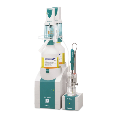
Figure 1 The Titrando system .......................................................................... 1
Figure 2 Front 815 Robotic USB Sample Processor XL .................................... 10
Figure 3 Rear 815 Robotic USB Sample Processor XL ..................................... 11
Figure 4 Connector strip ............................................................................... 12
Figure 5 Sample rack 6.2041.840 ................................................................. 12
Figure 6 Connecting the computer ................................................................ 16
Figure 7 Connecting the Swing Head ............................................................ 18
Figure 8 Mounting the tower extension ........................................................ 19
Figure 9 Mounting the Swing Head to the tower extension ........................... 20
Figure 10 Mounting the 6.2058.090 robotic arm reinforcement ...................... 21
Figure 11 Robotic arms - standard model versions: .......................................... 22
Figure 12 Configuration data of the robotic arms ............................................ 23
Figure 13 Limitation screw on the robotic arm ................................................ 24
Figure 14 Mounting the robotic arm ............................................................... 25
Figure 15 Connecting a beaker sensor (for example 6.1462.150) .................... 26
Figure 16 Mounting the rinsing and aspiration tubings .................................... 27
Figure 17 Installing the rinsing tubings and the aspiration tip .......................... 32
Figure 18 Installing stirrer and electrode .......................................................... 33
Figure 19 Rod stirrer 802 Stirrer ...................................................................... 34
Figure 20 Magnetic stirrer 741 Stirrer .............................................................. 34
Figure 21 Connecting the tower stirrer ............................................................ 34
Figure 22 Connecting a pump ......................................................................... 35
Figure 23 MSB connections ............................................................................ 36
Figure 24 Connecting a dosing device ............................................................. 38
Figure 25 Connecting an MSB stirrer ............................................................... 38
Figure 26 Connecting the rod stirrer to the titration stand ............................... 39
Figure 27 Connecting the Remote Box ............................................................ 39
Figure 28 USB connectors ............................................................................... 40
Figure 29 Mounting the base plate ................................................................. 42
Figure 30 Installing the drip pan ...................................................................... 43
Figure 31 Attaching rack ................................................................................. 44
Figure 32 Mounting the safety shield .............................................................. 45
Figure 33 Beaker sensor on the tower ............................................................. 49
Figure 34 Spray nozzles - Mode of operation .................................................. 50
Figure 35 Connectors of the Remote Box ........................................................ 50
Figure 36 Pin assignment of remote socket and remote plug ........................... 51


