MRC COT Series User manual

Operation Manual
COLD TRAPS
COT-SERIES
PLEASE READ THIS MANUAL CAREFULLY BEFORE OPERATION
3, Hagavish st. Israel 58817 Tel: 972 3 5595252, Fax: 972 3 5594529
mrc@mrclab.com
MRC.9.20

1
Content
1 GENERAL............................................................................................................................. 3
1.1 INTRODUCTION ....................................................................................................................3
1.2 SAFETY................................................................................................................................3
1.2.1 User’s Qualification ........................................................................................................3
1.2.2 Proper Use ......................................................................................................................3
1.2.3 Improper Use ..................................................................................................................3
1.2.4 Warning Signs.................................................................................................................4
1.2.5 Hazards Related to the Instrument..................................................................................5
1.2.6 Other Hazards .................................................................................................................6
1.2.7 Safety Measures..............................................................................................................6
1.3 INSTRUMENT SYNOPSIS .......................................................................................................6
1.4 INSTRUMENT CONFIGURATION....................................................................................................7
1.4.1 COT-2000H Configuration..............................................................................................7
1.4.2 COT-5000H Configuration..............................................................................................7
1.4.3 COT-2000L Configuration ..............................................................................................8
1.4.4 COT-5000L Configuration ..............................................................................................8
1.5 CONTROL PANEL INSTRUCTION............................................................................................9
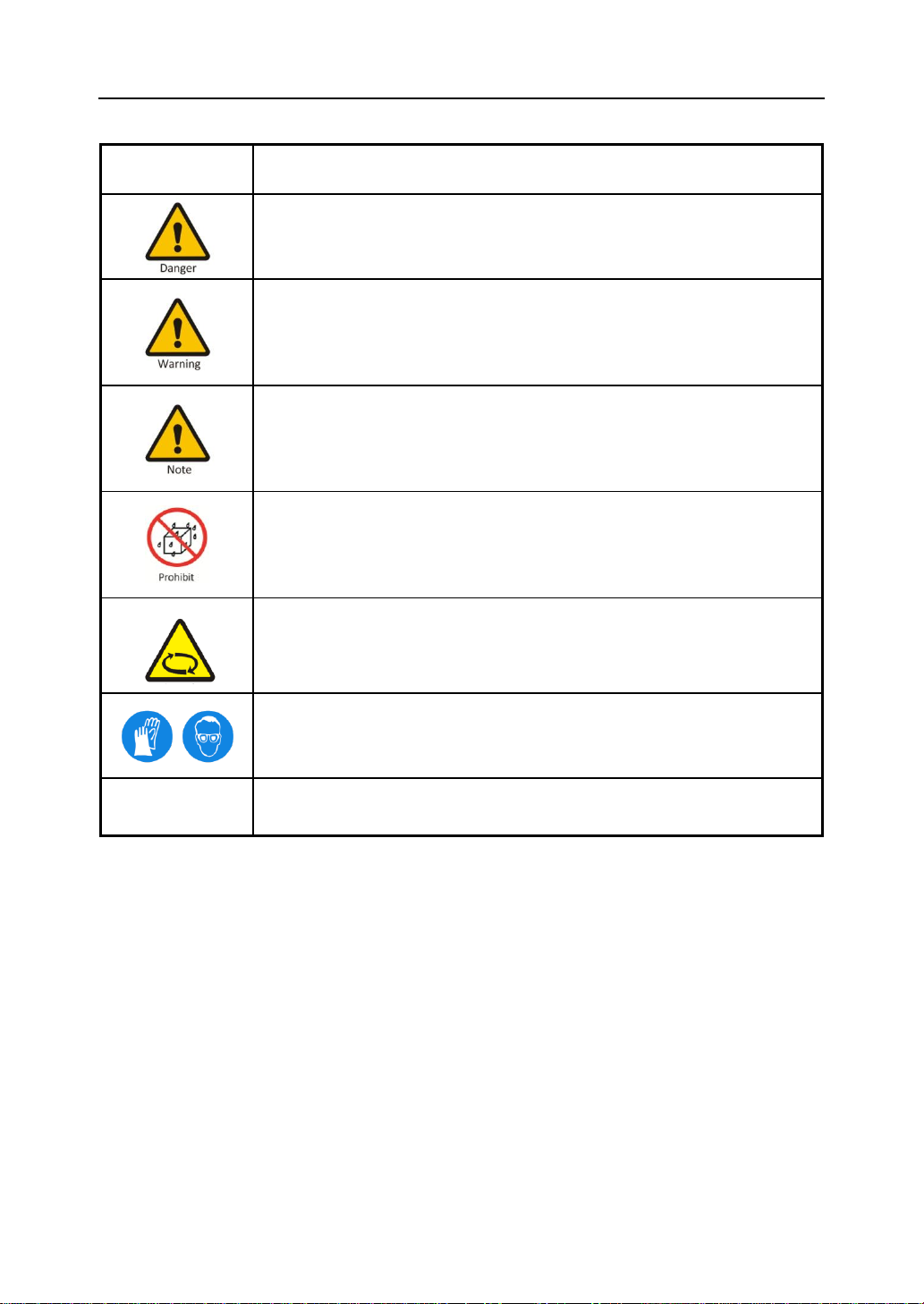
1.5.1 COT-2000H、COT-5000H Control Panel Instruction.......................................................9
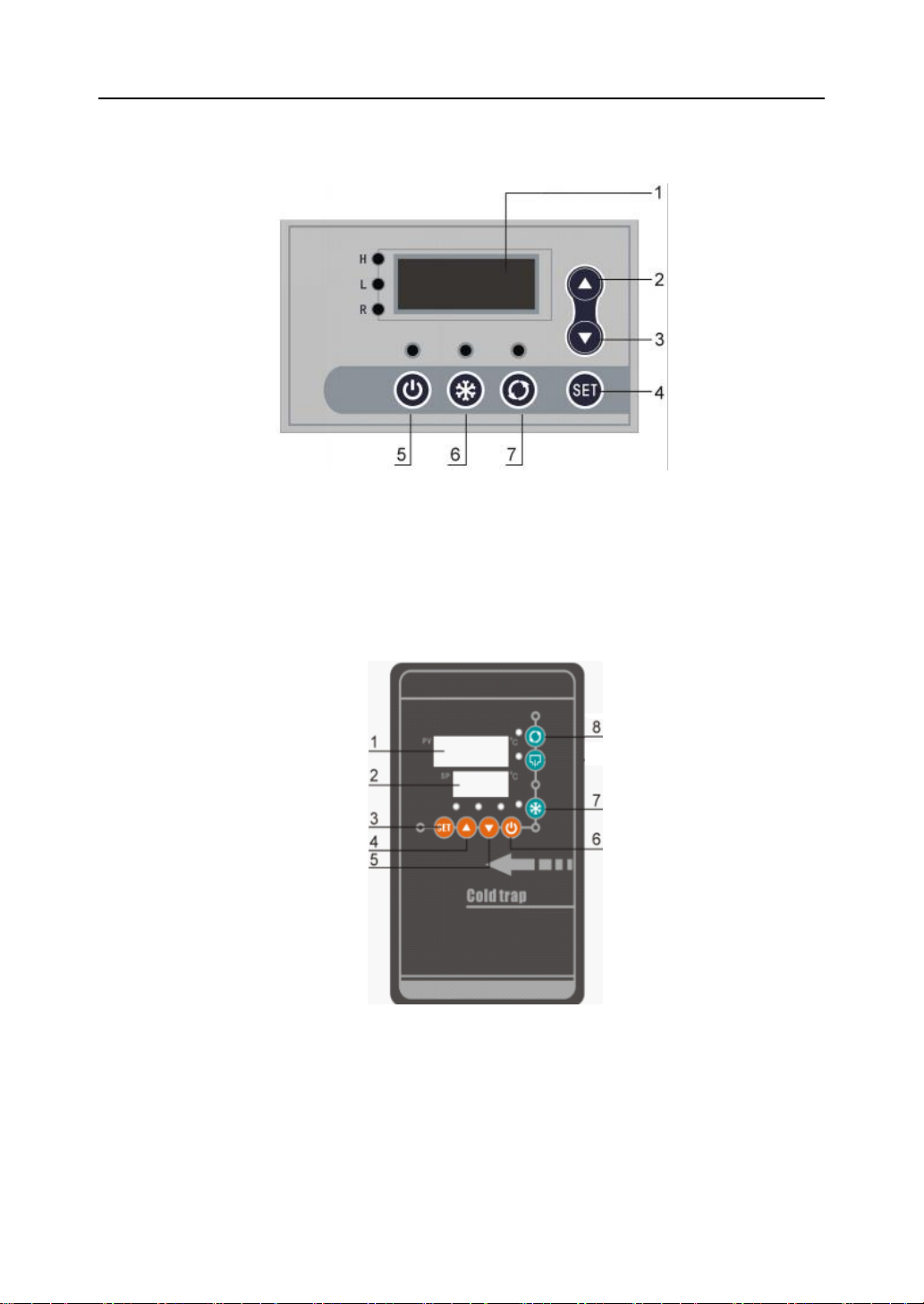
1.5.2 COT-2000L、COT-5000L Control Panel Instruction........................................................9
2UNPACKINGAND INSTALLATION.............................................................................. 10
3 TECHNICAL SPECIFICATIONS.................................................................................... 11
4. OPERATION.................................................................................................................... 12
4.1 POWER CONNECTION.........................................................................................................12
4.2 POWER ON .........................................................................................................................12
4.2.1 Close Breaker................................................................................................................12
4.2.2 Power Wwitch...............................................................................................................12
4.3 START REFRIGERATION SYSTEM ........................................................................................13
4.3.1 Start Refrigeration System at -40℃..............................................................................13
4.3.2 Start Refrigeration System at -80℃..............................................................................13
4.4 DRAIN ......................................................................................................................................13
4.5 POWER OFF ..............................................................................................................................14
5 PROTECTION FUNCTION............................................................................................... 14
6 MAINTENANCE AND MANAGEMENT.......................................................................... 14
6.1 MANAGEMENT...................................................................................................................14

2
6.2 MAINTENANCE OF COOLING SYSTEM ................................................................................15
6.3 MAINTENANCE REQUIREMENT ..........................................................................................15
6.4 COMMON FAILURES AND TROUBLESHOOTING ....................................................................16

3
1 GENERAL
1.1 Introduction
Thanks for using “COT series cold traps”. This operation manual stated the installation,
using, maintaining and servicing of cold traps. Before using this instrument, please ensure that
you have read and understood this manual completely.
1.2 Safety
This chapter described the installation, safety rules in the process of using “COT series cold
traps”. Users must grasp the related warning signs, strictly abide by the operation procedures to
ensure the security of the equipment and personal and avoid the occurrence of accident.
1.2.1 User’s Qualification
COT series cold traps must be operated by the person who has the practical operating
experiences and can grasp of the detailed requirements in this manual. Otherwise, it must be used
under the guidance of the person who has the related technology skills.
1.2.2 Proper Use
COT series cold traps are required to be installed indoor. It is used to capture water vapor
and harmful gases emission from vacuum drying oven and pressure reduced concentration
device, improving efficiency of vacuum system, extending life-span of vacuum pump.
1.2.3 Improper Use
The operation which does not abide by the related stipulations in this manual are regarded as
improper use. Any damage caused by improper use will be responsible by the users themselves.
Do not use it under below conditions:
a)Explosive gas atmospheres or explosive dust environment;
b)The places which the power supply is not in conformity with the requirements;
c)High magnetic fields, corrosive environment;
d)The gas which can corrode SUS304.

4
1.2.4Warning Signs
Sign
Description
Danger
It shows that the situation is very dangerous and will lead to death or
serious injury.
Warning
It shows that the situation is very dangerous and will lead to death or
serious injury
Note
It shows that the situation is very dangerous and will lead to injury.
Prohibit
Get wet in the rain or splashing water.
Note
Do not close to the rotary parts
Note
Please wear protective equipment, otherwise may cause personal injury
Reminder
Reminder
May cause equipment damage.
Especially pay attention to each warning sign.

5
1.2.5 Hazards Related to the Instrument
Please pay attention to the following safety tips:
Danger
Do not use it in explosive gas atmospheres or explosive dust
environment.
Prohibit
Do not use it outdoor. Get wet in the rain or splashing water will
cause electrification on metallic shell surfaces, and will cause
casualties.
Warning
Make sure that the power supply is in conformity with the
requirements on the nameplate.
Please place the equipment equipotential connection and earthed
reliably.
Before open the equipment enclosure for maintenance and repair, be
sure to disconnect the power supply, then operate it after 5s, ensure
the residual voltage release to safety value to avoid electric shock.
Do not use it before install the shell to avoid electric shock.
If found refrigerant leak, please take ventilation measures to reduce
refrigerant content in the air as soon as possible.
The recycling material should has no corrosive on SUS304.
Note
Please disconnect the power supply and then troubleshooting if there
is any abnormal circumstances when using it, or contact Professional
maintenance personnel ccordingly.
Please wear labor insurance gloves when cleaning, maintenance and
repair the instrument. Beware of condenser fin injury.
Note
Note
Do not close to rotary parts to avoid personnel injury.
Reminder
Reminder
Do not use it under high temperature and moist ambient. Otherwise it
will affect its normal running and life span.
Clean the condenser regularly. The cooling capacity of the equipment
will be reduced and its power consumption will be increased when
the condenser is clogged with dirt.
Keep well ventilation near the inlet/outlet of the instrument. Do not

6
put any objects near the outlet within 0.7m. If the inlet and outlet
blocked, the cooling capacity will be decreased.
Keep good ventilation around the Instrument.
1.2.6 Other Hazards
Warning
Acid, alkali and other corrosive materials will damage the equipment
insulation, its components performance and service life will be affected.
Do not contact refrigerant with food, medicines, tobacco, etc., to avoid
personal injury.
1.2.7 Safety Measures
Please wear personal protective equipment such as protective glasses,
protective clothing and gloves when operating this instrument.
1.3 Instrument Synopsis
The cold trap is cooled by a compressor to reduce the temperature of the trap wall inside the
vessel, and the gas recovered by the condensation becomes a non-gaseous state, and it will be
stored in the vessel and then discharged.

7
1.4 Instrument configuration
1.4.1 COT-2000H Configuration
Figure 1.4.1
1. SUS304 knob 2.Sealing flange 3.Control panel
4.Wheel 5.Breaker 6.Power cord
7.Air outlet 8.Liquid outlet 9.Air inlet
1.4.2 COT-5000H Configuration
Figure 1.4.2
1. SUS304 knob 2. Sealing flange 3. Breaker
4. Power cord 5. Wheel 6. Control panel
7. Air inlet 8. Liquid outlet 9. Air outlet

8
1.4.3 COT-2000LConfiguration
Figure 1.4.3
1. SUS304 knob 2.Sealing flange 3.Control panel
4.Wheel 5.Breaker 6.Power cord
8 Air outlet 9 Liquid outlet7 Air inlet
1.4.4 COT-5000L
Configuration
Figure 1.4.4
1. SUS304 knob 2.Sealing flange 3.Control panel
4 Air outlet 5 Air inlet 6 Breaker
7 Power cord 8 Liquid outlet 9 Wheel

9
1.5 Control Panel Instruction
1.5.1 COT-2000H、COT-5000H Control Panel Instruction
Figure 1.5.1 Control Pane
1 Temperature display window 2 Up 3 Down
4 Set 5 Power Switch 6Cooling Switch
7Circulaion Switch (disabled)
1.5.2 COT-2000L、COT-5000LControl Panel Instruction
Figure 1.5.2 Control Panel
1 Measured value and Menu display window 2 Set value display window
3 Set 4 Up 5 Down 6 Power Switch
7 Cooling Switch 8 Circulaion Switch (disabled)

10
2Unpacking and Installation
1)After unpacking the case, please read the operation manual carefully, and check
whether the components are enough according to the packing list.
2)Place the device steady, place more than 12h and then start debugging.
3)Keep well ventilated, the environment temperature should less than 35℃.
Note: Do not cover the air inlet/outlet!
4)Connect air outlet with vacuum device, connect air inlet with the device which need to
be vacuumized.
5)Before using the instrument, please clean the liquid on the surface of shell.
6)Do not use it outdoor.

11
3 Technical specifications
Model
COT-2000H COT-2000L COT-5000H COT-5000L
No-load lowest
temperature(℃)
-40
-80
-40
-80
Cooling method
Direct cooling/Indirect cooling
Ambient
temperature(℃)
5~25
Relative humidity (%)
≤70
Power supply(V/Hz)
220-240V~, 50Hz
Temperature display
Digital display
Sensor grade
Pt100
Setting mode
Can be set arbitrarily within working temperature range
Safety protection
Time-delay, over-current, over-heat
Dehumidification
capacity
Max.1kg(water)
Max.1kg
(water )
Max.4kg
(water )
Max.4kg
(water )
Cooling
capacity(
W)
-10℃
640
-
920
-
-20℃
400
-
520
-
-30℃
200
-
280
-
-
-40℃
20
260
40
400
-60℃
-
110
-
200
-80℃
-
40
-
60
Refrigerant
R404A
R404A、R23
R404A
R404A、R23
Overall power(W)
819
1580
835
1602
Overall current(A)
3.7
7.2
3.8
7.3
Bath size(mm)
Ф160×240
Ф160×240
Ф220×240
Ф220×240
Bath material
304
304
304
304
Dimensions
W×D×H(mm)
360×590×890
438×528×1190
573×583×1053
506×730×1388
Net weight(kg)
60
100
85
120

12
4. Operation
4.1 Power Connection
The power must be provided in accordance with the requirements on the equipment
nameplate.
1)The power supply must be grounding reliably.
2)Regarding single-phase power recirculating chiller, users need to provide three-pole safety
ground with protective grounding.
Note:
Users should be responsible for electric shock or equipment damage if
you don’t connect the power supply as described in 4.1.
4.2 Power on
4.2.1Close Breaker
Set the breaker which located on the right side of the instrument to ‘︱’, then connect power
supply. The power supply will be disconnected when the breaker at ‘0’.
4.2.2Power Wwitch
4.2.2.1 Start Refrigeration System at -40℃
Press power switch, the temperature display window will
shows(Figure4.2.1). The window will shows the actual measured temperature(Figure 4.2.2) after
lights on 1s, users don’t need to set temperature.

13
Figure 4.2.1 Figure 4.2.2
4.2.2.2 Start Refrigeration System at -80℃
Press power switch, the temperature display window PV, SP will shows
(Figure4.2.3). The PV window will shows the actual measured temperature(Figure 4.2.4) after
1s, SV window will shows the previous set temperature (Figure 4.2.4). Users don’t need to set
SP temperature.
Figure 4.2. 3 Figure 4.2. 4
4.3 Start Refrigeration System
4.3.1 Start Refrigeration System at -40℃
Press ‘ ’ after set all the parameters, the compressor will start working after delay-time, the
cooling system will working continuously.
4.3.2 Start Refrigeration System at -80℃
Press ‘ ’ after set all the parameters, the indicate light on, cold1 light blinking(on delay
mode), the high temperature device will start working after time-delay, the low temperature
device will start working when it reached set temperature and cold2 light on, the cooling system
will working continuously after low temperature device start working.
4.4 Drain
Please drain liquid regularly according to recovered material amount. Open drain valve

14
when the chamber temperature close to room temperature.
4.5 Power Off
Please close the cold trap according to below steps to ensure its normal running.
Figure 4.5 Power off
5 Protection Function
1)Compressor itself is equipped with thermal protection, its main circuit has circuit breakers.
When the compressor temperature is too high or over current, automatically it will be
disconnect the power automatically.
2)Circuit breaker has overload protection and short circuit protection.
Note: The protection device has been set before leaving the factory, , users do not change it.
6 Maintenance and Management
Ensure to make the equipment running normally to increase its service life, users should do
daily maintenance and management. Before maintenance, please disconnect equipment power
supply, preparing tools, materials according to according to the specific requirements in the
operation manual. Otherwise, it will cause electric shock or damage.
6.1 Management
1)Please use soft cloth to wipe the body surface regularly to keep it clean. Direct flush with
water is prohibited.
2)Other parts are prohibited from entering the liquid except circulating system.
3)Do not use a brush, polishing powder, acid and thinner etc. to clean surface of the body in

15
case of coating damaged.
4)The liquid storage tank must be dried after cleaning in case of pollute the bath fluid when
using it next time.
5)Please check the equipment connection pipe regularly, if found aging or damage, please
replace it according to original specifications.
6.2 Maintenance of Cooling System
In order to maintain the refrigeration effect, please clean up the cooling system (condenser)
regularly. Please follow the steps below:
1)Turn-off the power supply.
2)Take down the screws then pull the side panel down.
3)Clean up the dust on the condenser fin (Suggest to use cleaner or soft brush to clean it
along the direction of the rib.
Condenser Condenser fin
Figure 6.2
Note:
Do not touch condenser fin in case of injure hands!
4)After cleared, install the side panels in place.
6.3 Maintenance Requirement
1)Equipment maintenance must be done by the professional technical personnel or the
company authorized maintenance personnel.

16
2)If the equipment needs to return to factory for maintenance, please contact us.
1)3)Before return to our factory:
a)Please fill in fault information records and feedback to us for reference.
b)Please add equipment with safety packaging to avoid shock, collision of the equipment
in transit.
6.4 Common failures and troubleshooting
Table 6.4 Failures and troubleshooting
No.
Failures
Possible Reason
Troubleshooting
1
No display on touch
screen after power
on
Power supply is not connected
Check the power supply
2
Display “-EO-”
Sensor poor contact
Plug sensor plug
Replace sensor
3
Display “-E2-”
Sensor breakdown
Replace sensor
4
Temperature lose
control
Voltage fluctuation range large
Restart the device after
voltage stabilization
Temperature controller connection
failure
Stop using it and contact us
or professional maintenance
personnel
Temperature controller failure
5
Compressor is
running, but
equipment
refrigeration
effect is poor
Outer ambient temperature is too
high
Reduce the ambient
temperature
Refrigerant leakage
Stop using it and contact us
or professional maintenance
personnel
6
Compressor not
running, has
abnormal noise
starting capacitance breakdown
Compressor breakdown
7
Abnormal
downtime in
working process
Temperature controller failure
Compressor over temperature
protection
Improve the ventilation
environment,; check
whether the condenser fan
is jammed or not

17
8
Vacuum lost
Sealing problem
Check the sealing of upper
cover
9
Air outlet has no
airflow or airflow
abnormal
The fan has not started
Stop using it and contact us
or professional maintenance
personnel
The fan
has
started
The fan was stuck
Blade deformation
Our company reserves the right to interpret this manual. If there is any change, there will be no
further notice.
This manual suits for next models
4
Table of contents
Other MRC Laboratory Equipment manuals
Popular Laboratory Equipment manuals by other brands

ROBOfiber
ROBOfiber 8INJ-GE-125R user manual

Optika Italy
Optika Italy B-60 Series instruction manual

Showa Denko
Showa Denko Shodex IC NI-424 Operation manual

Agilent Technologies
Agilent Technologies InfinityLab LC Series user manual

Hygiena
Hygiena Dualo 32 R2 Product instructions

Miele
Miele A 312 operating instructions