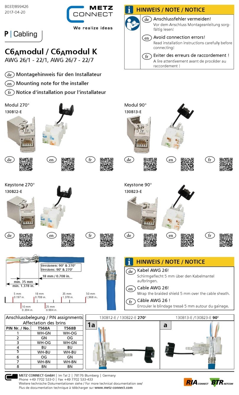
Metz Connect C Logline PT-C12 Quick start guide

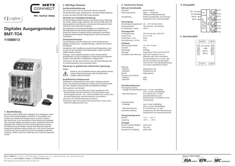
899257A
2020-03-27
Montagehinweis für den Installateur
Mounting note for the installer
Notice d‘installation pour l‘installateur
de
en
fr
PT-C12 110501
PT-F-C12 11050170
PTi-C12 11050108
PTi-F-C12 1105010870
DEUTSCH
de ENGLISH
en FRANÇAIS
fr
METZ CONNECT GmbH | Im Tal 2 | 78176 Blumberg | Germany
Phone +49 7702 533-0 | Fax +49 7702 533-433
Weitere Dokumentation siehe / additional documentation see / documentation supplémentaire voir www.metz-connect.com
A| Sicherheitshinweise A| Safety instructions A| Avis de sécurité
GEFAHR
Gefahr bedeutet, dass bei Nichtbeachtung Lebens-
gefahr besteht, schwere Körperverletzungen oder
erhebliche Sachschäden auftreten können.
DANGER
Danger means that non-observance may cause
risk of life, grievous bodily harm or heavy material
damage.
DANGER
Danger signifie que de la non observation des
consignes peut entraîner un risque mortel ou des
dommages matériels importants.
WARNUNG
Für die Montage, Inbetriebnahme und den Einsatz
des Geräts sind die jeweils länderspezifisch gültigen
Arbeitsschutz-, Unfallverhütungs- und Sicherheits-
bestimmungen einzuhalten und folgendes zu
beachten:
• Facharbeiter oder Installateure werden darauf
hingewiesen, dass sie sich vor der Installation
oder Wartung der Geräte vorschriftsmäßig ent-
laden müssen.
• Montage-, Wartungs- und Installationsarbei-
ten an den Geräten dürfen grundsätzlich nur
durch qualifiziertes Fachpersonal durchgeführt
werden.
• Qualifiziertes Fachpersonal im Sinne dieser
Anleitung sind Personen, die mit den beschrie-
benen Geräten vertraut sind und über eine
ihrer Tätigkeit entsprechenenden Qualifikation
verfügen.
WARNING
Follow the applicable country-specific safety at
work rules, the regulations for the prevention of
accidents and safety regulations when mounting,
bringing into service and using the device and
observe the following:
• Technicians and/or installers are informed that
they have to electrically discharge themselves as
prescribed before installation or maintenance of
the devices.
• Only qualified personnel is allowed to do
mounting, maintenance and installation work
on the devices.
• Qualified personnel in the sende of these inst-
ructions are persons who are well versed in the
use and installation of such devices and who
possess the necessary qualification for their job.
AVERTISSEMENT
Pour le montage, la mise en service et l‘utilisation
de l‘appareil il faut respecter les règlements en
vigueur selon le pays concernant la protection au
travail, la prévention des accidents et la sécurité et
de respecter aussi les avis suivants :
• Des travailleur qualifiés ou installateurs sont
avertis qui‘il est nécessaire de se décharger
correctement de l‘électricité avant d‘installer ou
d‘entretenir l‘appareil.
• Seul du personnel qualifié est autorisé à
effectuer le montage et l‘installation, voir
paragraphe personnel qualifié.
• Du personnel qualifié au sens de ces instructions
sont des personnes qui sont familiers avec
les appareils décrits et dont le qualifications
professionnelles sont en rapport avec leur
travail.
B| Beschreibung
C| Technische Daten C| Technical Data C| Données techniques
B| Description B| Description
C1|Anschlussbild
Connection diagram
Raccordements
C2|Prinzipbild
Principle diagram
Schéma de principe
Der Potentialtrenner / Signalwandler dient zur Trennung von
analogen Signalen im Bereich von 0 bis 10 V DC und 0 bis
20 mA DC oder zur Signalwandlung von 0 bis 10 V DC auf
0 bis 20 mA DC bzw. 0 bis 20 mA DC auf 0 bis 10 V DC. Die
Eingangs-, bzw. Ausgangssignale sowie die Versorgungs-
spannung sind gegenseitig potentialgetrennt. Am Gerät kann
wahlweise ein Eingangssignal 0 bis 10 V oder 0 bis 20 mA
angeschlossen werden. Funktion Potentialtrennung: Beim
PT-C12 wird das Eingangssignal 0 bis 10 V proportional auf
das Ausgangssignal 0 bis 10 V abgeglichen. Der PTi-C12
gleicht das Eingangssignal 0 bis 20 mA proportional auf das
Ausgangssignal 0 bis 20 mA ab. Funktion Signalwandlung
mit Potentialtrennung: Bei einer Signalwandlung von 0 bis
10 V auf 0 bis 20 mA bzw. 0 bis 20 mA auf 0 bis 10 V kann
das dabei umgewandelte Ausgangssignal mittels integrierten
Spindeltrimmer nachjustiert werden. Zusätzlich ist eine
Hand-Notbedienebene mit HAND-AUTO-Schalter mit Rück-
meldekontakt integriert. Über das frontseitige Potentiometer
kann in Schalterstellung HAND das Ausgangssignal 0 bis 10
V bzw. 0 bis 20 mA eingestellt werden. An der Klemme 10 V
steht eine konstante Ausgangsspannung von max. 10 V DC,
5 mA zur Verfügung. Der Eingang Y dient zur LED-Anzeige
der Ausgangsspannung Ua. Die Helligkeit der LED ist dabei
abhängig von der Höhe des Ausgangssignals (Brücke zwischen
Ua und Y). Alternativ kann ein externes Signal am Eingang Y
zur LED-Anzeige von 0 bis 10 V DC aufgeschaltet werden.
The potential isolator / signal converter is used for isolating
analog signals in the range from 0 to 10 V DC, and 0 to 20 mA
DC or for a signal conversion from 0 to 10 V DC to 0 to 20 mA
DC or 0 to 20 mA DC to 0 to 10 V DC. The input and output
signals as well as the supply voltage are electrically isolated
from each other. An input signal from 0 to 10 V or 0 to 20
mA can be connected to the device. Electrical isolation func-
tion: With the PT-C12, the input signal 0 to 10 V is adjusted
proportionally to the output signal 0 to 10 V. The PTi-C12
adjusts the input signal from 0 to 20 mA proportional to the
output signal from 0 to 20 mA. Function Signal conversion
with potential separation: With a signal conversion from 0
to 10 V to 0 to 20 mA, or from 0 to 20 mA to 0 to 10 V, the
output signal converted thereby can be readjusted using an
integrated spindle trimmer. In addition, a manual emergency
operating option with a MANUAL AUTO switch with feedback
contact is also integrated. The output signal from 0 to 10 V or
0 to 20 mA can be set via the front potentiometer when the
switch is in the MANUAL position. A constant output voltage
of max. 10 V DC and 5 mA is available at the 10 V terminal.
Input Y is used for the LED display of the output voltage Ua.
The brightness of the LED depends on the level of the output
signal (bridge between Ua and Y). Alternatively, an external
signal at the input Y can be connected to the LED display from
0 to 10 V DC.
Le sectionneur de potentiel / convertisseur de signal sert à
isoler les signaux analogiques dans la plage de 0 à 10 V c.c.
et 0 à 20 mA c.c. ou à convertir les signaux de 0 à 10 V c.c.
en signaux de 0 à 20 mA c.c. ou de 0 à 20 mA c.c. en 0 à 10
V c.c. Les signaux d‘entrée et de sortie ainsi que la tension
d‘alimentation sont séparés galvaniquement les uns des
autres. Un signal d‘entrée de 0 à 10 V ou de 0 à 20 mA peut
être raccordé au choix sur l‘appareil. Fonction de séparation de
potentiel: Sur le PT-C12, le signal d‘entrée 0 à 10 V est aligné
proportionnellement au signal de sortie 0 à 10 V. Le PTi-C12
aligne le signal d‘entrée 0 à 20 mA proportionnellement au
signal de sortie 0 à 20 mA. Fonction de conversion du signal
avec séparation de potentiel: Avec une conversion de signal
de 0 à 10 V en un signal de 0 à 20 mA ou de 0 à 20 mA en 0
à 10 V, le signal de sortie converti peut être réajusté à l‘aide
d‘un dispositif d‘ajustage à broche intégré. Un niveau de
commande manuelle d‘urgence avec commutateur AUTO
MANUEL avec contact de réponse est intégré en plus. Le signal
de sortie de 0 à 10 V ou de 0 à 20 mA peut être réglé à l‘aide
du potentiomètre avant en position MANUEL. Une tension de
sortie constante de 10 V c.c., 5 mA au max. est disponible sur
la borne 10 V. L‘entrée Y sert à l‘affichage à DEL de la tension
de sortie Ua. La luminosité de la DEL dépend du niveau du
signal de sortie (pont entre Ua et Y). En alternative, un signal
externe peut être connecté sur l‘entrée Y pour l‘affichage à
DEL de 0 à 10 V c.c.
Betriebsspannung 24 V AC/DC
Prüfspannung / Trennung 1000 V DC
Eingang / Spannung 0 bis 10 V DC
Eingang / Strom 0 bis 20 mA DC
Ausgang / Spannung fest 10 V DC / 5mA, fest
Ausgang / Spannung prop. 0 bis 10 V / max. 10 mA
Ausgang / Strom prop. 0 mA bis 20 mA
Ausgang / Strom Bürde max. 500 Ohm
Anzeige LED grün
Abmessungen (B x H x T) 35 x 69,3 x 60 mm
Gewicht 78 g
Betriebstemperaturbereich 0 °C bis 55 °C
Lagertemperaturbereich -20 °C bis 70 °C
Schutzart Gehäuse / Klemmen IP40 / IP20
Operating voltage 24 V AC/DC
Test voltage / separation 1000 V DC
Input / voltage 0 to 10 V DC
Input / current 0 to 20 mA DC
Output / fix voltage 10 V DC / 5mA, fix
Output / proportional voltage 0 to 10 V / max. 10 mA
Output / proportional current 0 mA to 20 mA
Output / current load max. 500 Ohm
Display green LED
Dimensions (W x H x D) 35 x 69.3 x 60 mm
Weight 78 g
Operating temperature range 0 °C to 55 °C
Storage temperature range -20 °C to 70 °C
Ingress protection
for housing / terminal block IP40 / IP20
Tension de service 24 V CA/CC
Tension d‘essai / séparation 1000 V CC
Entrée / tension de 0 à 10 V CC
Entrée / courant de 0 à 20 mA CC
Sortie / tension fixe 10 V CC / 5mA, fixe
Sortie / tension prop. de 0 à 10 V / 10 mA maxi.
Sortie / courant prop. de 0 mA à 20 mA
Sortie / courant résistance 500 ohms maxi.
Affichage DEL verte
Dimensions (L x H x P) 35 x 69,3 x 60 mm
Poids 78 g
Plage des températures
des service de 0 °C à 55 °C
Plage des températures
de stockage de -20 °C à 70 °C
Indice de protection
boîtier / bornes IP40 / IP20
• 110501: Raccordement avec borniers à vis
• 11050108: Raccordement avec borniers à ressort
(Push-In)
• 11050170: Raccordement avec borniers à vis
• 1105010870: Raccordement avec borniers à ressort
(Push-In)
• 110501: Anschluss mit Schraubklemmen
• 11050108: Anschluss mit Schraubklemmen
• 11050170: Anschluss mit Federkraftklemmen (Push-In)
• 1105010870: Anschluss mit Federkraftklemmen (Push-In)
• 110501: Connection with screw type terminal blocks
• 11050108: Connection with spring clamp terminal blocks
(push-in)
• 11050170: Connection with screw type terminal blocks
• 1105010870: Connection with spring clamp terminal blocks
(push-in)

METZ CONNECT GmbH | Im Tal 2 | 78176 Blumberg | Germany
Phone +49 7702 533-0 | Fax +49 7702 533-433
Weitere Dokumentation siehe / additional documentation see / documentation supplémentaire voir www.metz-connect.com
12
F | Display and Operating Elements F | Eléments d‘affichage et de commandeF | Anzeige- und Bedienelemente
1Schalter zur Auswahl von Hand- oder
Automatikbetrieb
2Potentiometer
Über das Potentiometer können im Handbetrieb
0 - 10 V bzw. 0 - 20 mA ausgangsseitig eingestellt
werden.
1Switch to set manual or automatic mode
2Potentiometer
When the device is set for manual mode the potenti-
ometer allows to set the output to 0 to 10 V or 0 to
20 mA.
1Commutateur pour régler le service manuel ou
automatique
2Potentiomètre
Le potentiomètre permet de régler en service manuel
0 à 10 V bzw. 0 à 20 mA à la sortie.
PT-C12 | 110501 - PT-F-C12 | 11050170
PTi-C12 | 11050108 - PTi-F-C12 | 1105010870
F|
HINWEIS
Zusätzliche Informationen und Dokumenta-
tionen stehen zum Download unter
www.metz-connect.com bereit.
110501 11050108
NOTE
Additional information and documentations are
available as download at www.metz-connect.com
110501 11050108
NOTICE
Des informations et documentations supplémentaires
comme la fiche technique sont disponibles pour
téléchargement sur www.metz-connect.com
110501 11050108
E| Montage & Demontage E| Mounting & dismounting E| Montage & démontage
• Zum Einbau in Elektroverteiler oder Kleingehäuse
E1 Das Gerät kann auf eine Tragschiene TH35 nach
IEC 60715 aufgerastet werden.
E2 Zur Demontage Entriegelungshebel mit einem
Schraubendreher lösen und Gerät nach vorne
abheben .
• Die Zugänglichkeit des Geräts zum Betreiben, Prüfen,
Besichtigen und Warten muss sichergestellt sein.
• Suitable for installation in electrical distribution cabinets or
small electrical enclosures.
E1 The device can be snapped on a rail TH35 according to
IEC 60715.
E2 For dismounting release the unlocking lever with a
screwdriver and remove the device to the front .
• The device has to be accessible for operating, testing,
inspection and maintenance.
• Se monte aux répartiteurs électriques ou petits boîtiers.
E1 L‘appareil peut être encliqueté sur un rail TH35 selon
IEC 60715.
E2 Pour démonter débloquer le levier de déblocage avec un
tournevis et retirer l‘appareil vers l‘avant .
• L‘accès à l‘appareil pour service, contrôle, inspection et
entretien doit être assuré.
E|
E1 E2
D1 Préparation du câble pour raccordement de l‘appareil
Dénuder les fils de 8 mm.
Poser des embouts appropriés sur les fils multibrins.
Variante a) Raccordement de l‘appareil avec borniers à vis
D2 Voir page 1, C1| raccordements et C2| schéma de
principe.
Insérer les fils dans les contacts respectifs et les fixer
avec un tournevis.
Variante b) Raccordement de l‘appareil avec borniers à
ressort
D3 Voir page 1, C1| raccordements et C2| schéma de
principe.
Les fils monobrin et les fils multibrins avec embouts
peuvent être directement insérés. Insérer le fil droit et
le presser jusqu‘à ce qu‘il s‘enclenche dans le ressort.
Pour les fils flexibles sans embout, appuyer sur le levier
de commande orange à l‘aide d‘un tournevis plat lors de
l‘insertion du fil.
D4 Pour débloquer le fil insérer un tournevis plat dans le
contact levier de commande orange, jusqu‘à ce que le
ressort s‘ouvre et retirer le fil.
D1 Cable preparation for device connection
Strip wires by 8 mm.
Put on appropriate wire end sleeves to stranded wires.
Variant a) Device connection with screw type terminal
blocks
D2 See page 1 C1| connection diagram and
C2| principle diagram.
Insert the wires into the respective contacts and fix
them with a screw driver.
Variant b) Device connection with spring clamp terminal
blocks
D3 See page 1 C1| connection diagram and
C2| principle diagram.
Solid wires and stranded wires with end sleeves can be
directly pushed-in. Insert the wire straightly and press
until the wire snaps into the spring. For flexible wires
without end sleeves, press the orange operating lever
with a flat-bladed screwdriver when inserting the wire.
D4 To release the wire enter a flat-bladed screwdriver into
the orange operating lever until the spring opens and
pull out the wire.
D1 Kabelvorbereitung
Adern 8 mm abisolieren.
Litzenleiter mit passender Aderendhülse versehen.
Variante a) Geräteanschluss bei Schraubklemme
D2 Für Anschluss siehe Seite 1, C1 | Anschlussbild und
C2 | Prinzipbild.
Adern in die entsprechende Klemmenöffnung einführen
und mit Schraubendreher fixieren.
Variante b) Geräteanschluss bei Federkraftklemme
D3 Für Anschluss siehe Seite 1, C1 | Anschlussbild und
C2 | Prinzipbild.
Volldrähte und Litzenleiter mit Aderendhülsen können
direkt gesteckt werden. Draht gerade einführen bis
der Draht in die Feder einrastet. Bei flexiblen Drähten
ohne Aderendhülsen beim Einführen den orangen
Betätigungshebel mit einem Schlitz-Schraubendreher
drücken.
D4 Zum Lösen des Drahtes Schlitz-Schraubendreher in den
orangen Betätigungshebel drücken bis die Feder öffnet,
dann Draht herausziehen.
DEUTSCH
de ENGLISH
en FRANÇAIS
fr
DANGER
Risk of death by electric shock!
Switch off all electrical power supply before
starting work on energized parts.
DANGER
Danger de mort par choc électrique !
Avant toute intervention sur des pièces
conductrices, mettre des lignes électriques hors
tension.
D| Vorbereitung und Anschluss D| Preparation and Connection D| Préparation et Raccordement
GEFAHR
Lebensgefahr durch Stromschlag!
Vor Arbeiten an stromführenden Teilen elektrische
Leitungen spannungsfrei schalten.
D|
D1
D3 D4
D2
8 mm
variant b)
variant a)
variant b)
max. 2,5 mm²
This manual suits for next models
7
Other Metz Connect Control Unit manuals
