manuals.online logo
Brands
  1. Home
  2. •
  3. Brands
  4. •
  5. Metz Connect
  6. •
  7. Control Unit
  8. •
  9. Metz Connect BTR Netcom E-DAT User manual

Metz Connect BTR Netcom E-DAT User manual

Beschriftungsbogen A4
Label sheet A4 899789-01
Ausführung / Version Bestell-Nr. / P/N
Beschriftungsbogen A4
Label sheet A4
Anlegewerkzeug LSA PLUS®
Crimp tool LSA PLUS®
Anlegewerkzeug LSA PLUS®
Crimp tool LSA PLUS®130818-E
Ausführung / Version Bestell-Nr. / P/N
BTR NETCOM GmbH
Im Tal 2
78176 Blumberg / Germany
Tel. +49 7702 533-0
Fax +49 7702 533-433
www.btr-netcom.com 052007/2.000/13/L/899 641
AP-Gehäuse für 6x8 Module
reinweiß und lichtgrau
Surface Mount Housing for 6x8 modules
pure white and light grey
Montageanleitung
Termination Instructions
Zubehör
Accessories
Hinweis für Verwender und Monteure
Unsere Anschlusssysteme und Verteilerprodukte für strukturierte Gebäudeverkabelungen entsprechen den gültigen Normen EN
50173-1:2002 und IEC 60603-7. Bei Komplettierung der Anschlüsse muss der Verwender/Montagebetrieb prüfen und beachten,
dass nur Patch- und Anschlusskabel, die die EN-/ IEC-Normen erfüllen, verwendet werden. Lassen Sie sich ggf. vom Lieferanten den
Nachweis geben, dass die eingesetzten Kabel und Stecker der Norm entsprechen. Die Verwendung von nicht normgerechten Komponenten
bedeutet den Verlust der Mängelrechte auch innerhalb der Lieferkette unserer Produkte. Die Installation ist nur von Fachpersonal durchzufüh-
ren. Hierbei sind die Sicherheitsanforderungen nach EN 60950 zu beachten. Bitte beachten Sie auch, dass keine starken mechanischen Ein-
wirkungen und Beanspruchungen beim Ein- und Ausstecken des Benutzerkabels nach oben, unten oder seitlich auf den elektrischen Kontaktbe-
reich der Steckverbindung (z. B. durch Ziehen am Kabel u. a.) erfolgen. Für dadurch entstehende Schäden haften wir nicht. Bitte übergeben
Sie diesen Hinweis auch an den Endverbraucher.
Achtung!
Ausstecken (Ziehen des RJ45-Steckers) nur bei zuvor ausgeschaltetem Gerät ohne Spannung. Ausstecken, insbesondere wiederholtes Ausstecken
unter Spannung (bei Verwendung von Power over Ethernet PoE) kann zu Schäden an den Kontakten der RJ45-Steckverbindung führen.
Notes for user and installer
Our termination systems and patch products for generic cabling meet the active standards EN 50173-1:2002 and IEC 60603-7. The user or
installer has to check and take care to use solely patch and termination cables that meet the EN-/IEC standards when completing the installa-
tion. If necessary ask your supplier to certify that the installed cables and plugs meet the standards. The use of non-standard components
means the loss of rights accruing from defects even within the supply chain of our products. Installation only by qualified personnel. Electrical
Safety per EN 60950. Furthermore, please pay attention that the electric contact area of the plug connection is not exposed to high mechani-
cal effects or strain (e.g. by pulling the cable etc.) when the user cable is plugged in or out upwards, downwards or sidewards. We do not take
over liability for any damage. Please give this note to end users, too.
Attention!
Before unplugging the RJ45 plug make sure that the device is switched off and is no longer energised. Unplugging, particularly repeated
unplugging of an energised device (when using Power over Ethernet PoE) may damage the contacts of the RJ45 plug connection.
AP-Verteiler - Aufputzgehäuse
Surface mount distributor - Surface mount housing
Das 6x8 AP-Gehäuse wird zur Aufputzmontage der Funktionsmodule (wie z. B.
E-DAT C6 6x8 1HE Modul Cat.6, E-DAT modul 6 x 8(8) 1HE Patchfeld, OpDAT 6M,
E-DAT 6x8 Cat.6 Modul und ISDN-TE-Hub 1/5) verwendet.
The module housing 6x8 AP is used for surface mounting of the 6fold function modules 1HE
like e.g. E-DAT 6x8 Modul.
Der E-DAT 6x8 AP-Verteiler ist zur Aufputzmontage als 6-fach-Verteiler oder Anschlussdose für
die strukturierte Gebäudeverkabelung geeignet.
E-DAT 6x8 surface mount distributor is suited as a 6 fold distributor or wall outlet in structured
building cabling.
GFarbe RAL 7035 lichtgrau und RAL 9010 reinweiß
Colour RAL 7035 light grey and RAL 9010 pure white
3 4
5 6
Mittels Schablone Löcher für die Wandmontage boh-
ren.
Drill the holes through the template.
Gehäuseboden an die Wand montieren.
Screw the housing base plate to the wall.
Modul in Gehäuseboden einbauen.
Fit the rack to the housing base plate.
Kabel konfektionieren und anschließen.
Prepare the cables and terminate them according to
the rack instruction sheet.
Nach der Kabelmontage das Modulgehäuse verschlie-
ßen.
Fit the rack cover after terminating the cables.
Die beiliegende Schablone von der Montageanleitung
abtrennen und an einer geeigneten Stelle des Kabel-
kanals positionieren. Darauf achten, dass die Schablo-
ne richtigherum angelegt wird (Pfeil muss in Kanal-
richtung zeigen)!
Cut out the template from these instructions and posi-
tion it at a suitable point adjacent to the cable condu-
it. Make sure that it is correctly positioned (with the
arrow pointing at the cable conduit).
1 2 7
Oberteil des Aufputzgehäuses aufsetzen.
Fit the housing cover.
Öffnen des Gehäuses:
mit Schraubenzieher Abdeckung
anheben und abnehmen.
Opening the housing:
Lift the cover with a screwdriver
and remove it.
Öffnen des Aufputzverteilers
Opening the surface mount housing
Allgemeine Hinweise / Montage
General Notes / Mounting
Montage
Mounting
Montageschablone
Drill Hole Template
Montageschablone
Drill Hole Template

Other Metz Connect Control Unit manuals

Metz Connect MR-SI4 User manual

Metz Connect

Metz Connect MR-SI4 User manual

Metz Connect C Logline PT-C12 Quick start guide

Metz Connect

Metz Connect C Logline PT-C12 Quick start guide

Metz Connect MR-AO4 User manual

Metz Connect

Metz Connect MR-AO4 User manual

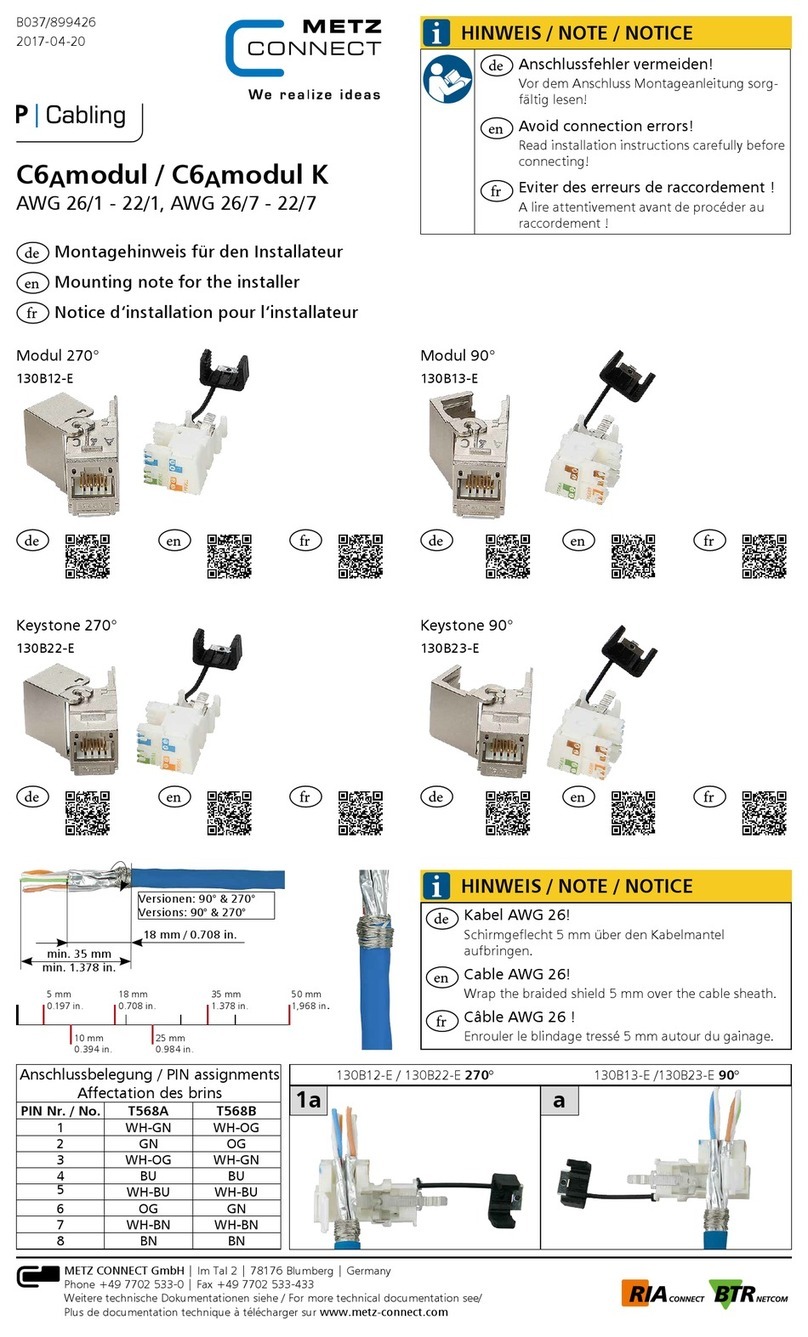
Metz Connect C6Amodul Quick start guide

Metz Connect

Metz Connect C6Amodul Quick start guide

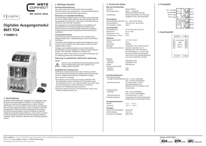
Metz Connect BMT-TO4 User manual

Metz Connect

Metz Connect BMT-TO4 User manual

Metz Connect C6Amodul Quick start guide

Metz Connect

Metz Connect C6Amodul Quick start guide

Popular Control Unit manuals by other brands

Faraday 8701 INSTALLATION INSTRUCTIONS AND WIRING

Faraday

Faraday 8701 INSTALLATION INSTRUCTIONS AND WIRING

Giacomini KPM30 Series Technical leaflet

Giacomini

Giacomini KPM30 Series Technical leaflet

Dungs GasMultiBloc MBC-65 Series instructions

Dungs

Dungs GasMultiBloc MBC-65 Series instructions

Siemens SIMATIC CPU 410 System manual

Siemens

Siemens SIMATIC CPU 410 System manual

Victorian Plumbing Arezzo installation guide

Victorian Plumbing

Victorian Plumbing Arezzo installation guide

Denkovi smartDEN IP-16R-MT user manual

Denkovi

Denkovi smartDEN IP-16R-MT user manual

Velleman-Kit K2636 Assembly manual

Velleman-Kit

Velleman-Kit K2636 Assembly manual

Waveshare 4.2inch e-Paper Module user manual

Waveshare

Waveshare 4.2inch e-Paper Module user manual

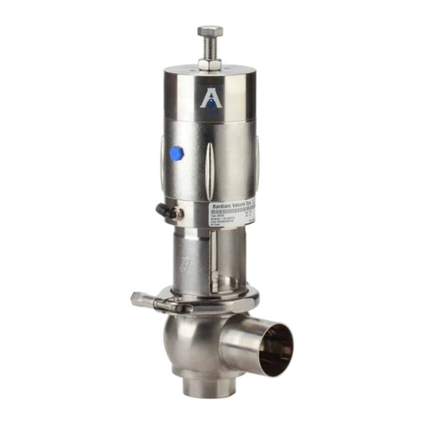
Bardiani BBZS5 Operating and maintenance instructions

Bardiani

Bardiani BBZS5 Operating and maintenance instructions

Tash SICARE Pilot user manual

Tash

Tash SICARE Pilot user manual

Samson 3353 Original instructions

Samson

Samson 3353 Original instructions

McElroy Pitbull 14 instruction sheet

McElroy

McElroy Pitbull 14 instruction sheet

Graco B52100 Instructions and parts

Graco

Graco B52100 Instructions and parts

Berker 8026 21 Series user manual

Berker

Berker 8026 21 Series user manual

Charger SP Series Programming manual

Charger

Charger SP Series Programming manual

Harvia SIGMA CS110 manual

Harvia

Harvia SIGMA CS110 manual

Zenner Electronic Data Capture Module Installation and operating instructions

Zenner

Zenner Electronic Data Capture Module Installation and operating instructions

Mobeye ThermoGuard TwinLog CML2255 PORTAL USER MANUAL

Mobeye

Mobeye ThermoGuard TwinLog CML2255 PORTAL USER MANUAL

manuals.online logo
manuals.online logoBrands
  • About & Mission
  • Contact us
  • Privacy Policy
  • Terms and Conditions

Copyright 2025 Manuals.Online. All Rights Reserved.