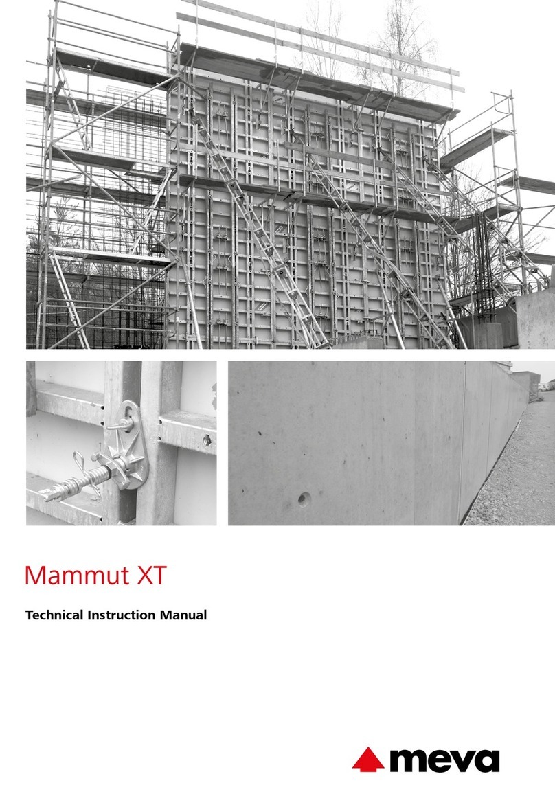
Meva MevaLite Owner's manual

Technical Instruction Manual
June 2022
MevaLite

ML-2
MevaLite
MevaLite is a modular formwork system that can be either handset or
gang formed. It is suitable for use on residential, commercial, industrial
and highway projects.
The panels are composed of closed profile powder coated aluminum
frames and a high grade alkus composite facing that provides an
excellent concrete finish. Panels are connected with the MEVA assembly
lock which results in fast and ecient assembly with no nuts and bolts.
A complete formwork assembly including accessories weighs about 12
psf. Panels are designed for a maximum lateral concrete pressure of 1350
psf when properly supported.
MevaLite panels are available in 4 different heights (9’, 6', 4’, and 3’) and
in 5 different widths (3’, 2’, 1’-6”, 1’-0”, and 6”). In addition, 2’-6" wide
multi-purpose panels are available in each height. These panels have
multi-adjustment profiles for placing ties or column clamps and are ideal
for forming 90° corners, columns, pilasters, and connections to existing
walls.
Introduction
Available accessories include aluminum fillers (1”, 2”, and 3”), inside
corners (12”x12”), outside corners, push-pull props, and walkway
brackets. Threaded nuts built into the panels allow for easy attachment
of accessories.
Please check here for the most up to date manual:
https://www.meva.net/en-us/tools-downloads/downloads
And please check here for the MEVA YouTube channel:
https://www.youtube.com/user/mevalive/featured
Wall formwork
Technical Instruction Manual / June 2022

MevaLite
ML-3
Safety Rules &
Recommendations:
ÆThis manual contains information and instructions on how to use
MEVA equipment in a safe and ecient manner. All construction
personnel involved with the use of this equipment (“User”) must be
familiar with the contents of this manual.
ÆThe user is responsible for identifying and complying with all
applicable government regulations, codes, and ordinances in the use
of this equipment.
ÆMEVA equipment must be erected, used, and dismantled in
accordance with this manual, safe practices, and all applicable
industry standards developed and published by the American
Concrete Institute (ACI), the American National Standards Institute
(ANSI) and the Occupational Safety and Health Administration
(OSHA). Additional workplace safety precautions should be taken
where necessary.
ÆMost examples shown are standard applications that will occur in
practice most often. For applications not covered in this manual,
please contact your MEVA representative for advice.
ÆMany of the details in this manual show specific conditions and
situations during different stages of assembly and are therefore not
always complete. Any equipment or safety accessories not shown in
the details must still be used in accordance with all applicable rules
and regulations.
ÆIn order to assure proper fit and load capacity, do not combine this
equipment with components of other manufacturers unless directed
by a MEVA representative.
ÆThe user must inspect all equipment before each use. Never use
equipment that is damaged, deformed, or weakened due to wear or
corrosion.
ÆNever oil or wax MEVA assembly locks.
ÆThe user must ensure the stability of all components during all
phases of construction.
ÆFor gang formwork, the user should always establish the number
and location of lift points to equalize load on lift brackets and
ensure that no individual component is overloaded.
ÆIt is the user’s responsibility to adjust the pour rate and placement
methods in accordance with ACI 347 for the concrete mixture and
the specific jobsite conditions at the time of placement so that the
specified maximum lateral concrete pressure is never exceeded.
ÆCertain applications will result in a maximum lateral concrete
pressure lower than the system panel capacity. Refer to specific
sections of this manual, MEVA application drawings, or consult your
MEVA representative.
ÆWhen stripping gang formwork, never use the crane to break the
concrete bond. Instead, use suitable tools such as pry bars or wood
wedges. Secure the lift brackets prior to removal of ties, anchors,
and/or bracing.
ÆDo not nail into aluminum panel frames.
Contents
The MevaLite Panel................................................................................4
Multi-Purpose Panels .............................................................................5
The alkus Sheet......................................................................................6
Panel Connection...................................................................................7
Tie Systems............................................................................................8
System Panel Sizes ..........................................................................9 - 11
Tie Placement ......................................................................................12
Stacking Panels....................................................................................13
90°Corners ...................................................................................14 - 17
Articulated Corners.......................................................................18 - 20
Stripping Corners..........................................................................21 - 27
Columns .......................................................................................28 - 29
Fillers ............................................................................................30 - 31
Intersections ........................................................................................32
Bulkheads ....................................................................................33 - 34
Adjoining Walls....................................................................................35
Pilasters ...............................................................................................36
Pilasters at Corners ..............................................................................37
Wall Offsets.........................................................................................38
Vertical Offsets ....................................................................................39
Horizontal Panels .................................................................................40
Wall Braces...................................................................................41 - 43
Form Walkways ...................................................................................44
Crane Hook .........................................................................................45
Gang Forming...............................................................................46 - 47
Adjustable Shearwall Bracket...............................................................48
Assembly, Erection and Stripping ..................................................49 - 54
Transport .............................................................................................55
Service.................................................................................................56
Notes............................................................................................57 - 58
Product List..........................................................................................59
Wall formwork
Technical Instruction Manual / June 2022

ML-4
MevaLite
The MevaLite Panel
Fig. 4.1
MevaLite panel
Fig. 4.2
The aluminum frames are
manufactured of closed profiles which
are welded in mitered joints. These
profiles are provided with a groove
and an integrated protection for the
forming face.
Fig. 4.3
Large tie pockets allow for easy
insertion of any tie system (taper ties,
she-bolts, thru-rods).
Fig. 4.4
Pioneering panel connection with
MEVA assembly lock.
Fig. 4.5
The ergonomically designed cross
stiffeners are also made of closed
aluminum profiles. The profiles have
the shape of a bone: they are easy
to grab, and the risk of injuries is
eliminated.
Fig. 4.6
The multi-function profiles have
Dywidag threaded nuts inside which
allow for fast and safe attachment of
accessory parts.
Fig. 4.7
The tie-off bar allows safe working
on the formwork. Under no
circumstances should panels be lifted
or moved using these tie-off bars.
Tie-off bars should only be used with
suitable positioning device systems
as described in OSHA 1926-502(e),
supplied by others.
Or, provided the user adhere to
the guidance set forth in OSHA
1926.502(d)(15), 1926.502(d)(15)(i),
1926.502(d)(15)(ii), and all associated
sections, these tie-off bars may
be used with personal fall arrest
systems that meet the requirements
set forth in OSHA. It is the end
user's responsibility to ensure OSHA
requirements are met.
Fig. 4.1
Fig. 4.6
Fig. 4.5
Fig. 4.4
Fig. 4.3
Fig. 4.2
Fig. 4.7
Wall formwork
Technical Instruction Manual / June 2022

MevaLite
ML-5
Multi-purpose Panels
Multi-function profile
Frame
Standard tie hole
Dywidag-threaded nuts
Holes with threaded nuts in frame at
multi-adjustment profile elevation
Tie-off bar
Ø 1 1/16"
Fig. 5.1
Fig. 5.3
The multi-purpose panels are ideal
for forming 90° corners, columns,
pilasters, bridge abutments and
connections to existing walls.
The panels are provided with multi-
adjustment profiles where column
clamps or ties are mounted.
The panels come with pilot holes
on the back side for drilling
selected tie holes at exact
locations.
Plug the unneeded tie holes with
Plug D27/30.
The 9’ panels have 3 multi-
adjustment profiles, the 6’ and 4’
panels have 2 multi-adjustment
profiles and the 3’ panel has 1
multi-adjustment profile.
Threaded sleeves are also provided
on the frame sides at each tie hole
elevation for tensioning screw
connections.
Description Ref.-No.
ML-multi-purpose panels
9’x2.5’.......................................22-500-25
6’x2.5’.......................................22-501-25
4’x2.5’.......................................22-502-25
3’x2.5’.......................................22-503-25
Plug D27/30 ..............................29-902-61
Multi-adjustment profile
Ø 1 1/16" to Ø 1 1/4" conical
Threaded sleeves
for tensioning
screw connections.
2’-6”
3”
1 ½” 2” 2” 2” 2” 2” 2” 2” 2” 2” 2” 2” 2”
Ø1 1/16”
1 ½”
Fig. 5.2
Wall formwork
Technical Instruction Manual / June 2022

ML-6
MevaLite
The poly-propylene and aluminum
composite forming face has all
the positive properties of plywood
plus important advantages: longer
life span, greater load-bearing
capacity, better nail-holding ability,
fewer and easier repairs, 100 %
recyclability.
Besides the obvious advantages,
such as considerably reduced
cleaning effort, minimum
consumption of release agent
and an excellent concrete finish,
alkus offers substantial ecological
benefits. Substituting plastic
for wood saves valuable timber
resources. Also, the release of
highly toxic dioxin is avoided,
which is released in the process of
burning plywood (that is bonded
with phenolic resin). Used or
damaged alkus plastic sheets can
be recycled into the same product.
It is 100% recyclable, and the
manufacturer guarantees reaccept-
ance.
Fig. 6.3: Composite alkus plastic sheet structure
Frame profile + plywood face Frame profile + alkus sheet
Fig. 6.1: Negative impression in the concrete when using
panels with a conventional plywood face
Fig. 6.2: Smooth and even concrete surface as there is no
projecting profile of the panel frame
Plastic layer
Aluminum layer
Foamed plastic core
Aluminum layer
Plastic layer
The alkus Sheet
Wall formwork
Technical Instruction Manual / June 2022

MevaLite
ML-7
The panels are connected
quickly and eciently with the
EA-assembly lock regardless of
their orientation (Fig.7.1, 7.2).
The lock can be attached on the
frame at any position, and its
5-point contact not only draws
the panels together but aligns
them as well. Only a few hammer
blows are needed to create a
safe connection with perfect
alignment. Since the lock weighs
only 3.3lbs. it can be handled
easily.
Standard lock requirements are
shown in Figure7.4. Additional
locks are required for columns
and outside corners (refer to
respective sections for details).
Panels with aluminum or wood
fillers in between are connected
with the Uni-assembly lock22,
which can accommodate a
maximum filler width of 6.5"
(Fig.7.5).
Panel Connection
Description Ref.-No.
EA-assembly lock .......................29-205-50
Uni-assembly lock 22 .................29-400-85
Fig. 7.1 EA-assembly lock
Fig. 7.2 EA-assembly lock Fig. 7.3 EA-assembly lock
5-point contact
Standard Lock Requirements
Panel Edge Length Number of Locks
9' 4
6' 3
4' thru 1'-6" 2
1', 6" 1
Fig. 7.4 Fig. 7.5 Uni-assembly lock 22
6.5" MAXIMUM
Wall formwork
Technical Instruction Manual / June 2022

ML-8
MevaLite
Tie Systems
Description Ref.-No.
Articuated flange nut 15/120................................29-900-10
5/8" (15mm) Taper Tie Stock Sizes
16/41 - 16" Taper length, 41" Overall ..........2-500-2990131
24/49 - 24" Taper length, 49" Overall ..........2-500-2990133
32/57 - 32" Taper length, 57" Overall ..........2-500-2990135
Description Ref.-No.
Rental
5/8" (15mm) Threadbar 18".........................2-500-2990158
5/8" (15mm) Threadbar 42".........................2-500-2990156
5/8" (15mm) Threadbar 54".........................2-500-2990154
5/8" (15mm) Threadbar 72".........................2-500-2990152
Articuated flange nut 15/120................................29-900-10
Purchase
5/8" (15mm) Plastic Spacer Cone ................. 2-500-2990252
1" Stripping Tool for 5/8" Spacer Cone.........2-500-2990233
3/4" PVC Pipe Sch40 20ft ............................2-500-2990244
Description Ref.-No.
Rental
5/8" (15mm) Pass-Thru She-Bolt x 19"..........2-500-2990173
Articuated flange nut 15/120................................29-900-10
Purchase
5/8" (15mm) Threadbar 19'-1".....................2-500-2990140
5/8" (15mm) Neoprene Waterstop............... 2-500-2990237
Description Ref.-No.
Rental
5/8" (15mm) Steel Setting Cone...................2-500-2990180
5/8" (15mm) Threadbar 18".........................2-500-2990158
Articuated flange nut 15/120................................29-900-10
Purchase
5/8" (15mm) Threadbar 19'-1".....................2-500-2990140
5/8" (15mm) Neoprene Waterstop............... 2-500-2990237
Fig. 8.1 - 5/8" (15mm) Taper Tie, 1" to 3/4"
Fig. 8.2 - 5/8" (15mm) Threadbar
Fig. 8.3 - 5/8" (15mm) Pass-Thru She-Bolt
Fig. 8.4 - 5/8" (15mm) She-Bolt Steel Cone
5/8" (15mm) Taper Tie
5/8" (15mm) Threadbar
5/8" (15mm) Pass-
Thru She-Bolt X
19"long
5/8" (15mm) 18"Threadbar
(Reusable)
Articulated
flange nut 15/120
Articulated
flange nut 15/120
Articulated flange nut 15/120
Articulated flange nut 15/120
Neoprene
Waterstop
Neoprene Waterstop
(if needed)
2"
5/8" Spacer
Cone 1 1/2" Cone Depth
3/4" PVC Pipe Schedule 40
Length = Wall Thickness - 2"
5/8" (15mm) Threadbar Inner Tie Rod (Consumed)
Length = Wall Thickness - 4"
5/8" (15mm) Threadbar Inner Tie Rod (Consumed)
Length = Wall Thickness - 4"
5/8" (15mm) Steel
Setting Cone
5/8" (15mm) Taper Tie
SWL = 18.75 KIPS
Factor of Safety = 2:1
5/8" (20mm) Threadbar
SWL = 21.9 KIPS
Factor of Safety = 2:1
5/8" (15mm) Pass-Thru
She-Bolt
SWL = 21.9 KIPS
Factor of Safety = 2:1
5/8" (15mm) She-Bolt Steel Cone
SWL = 21.9 KIPS
Factor of Safety = 2:1
2"
4" Taper
Wall formwork
Technical Instruction Manual / June 2022

MevaLite
ML-9
System Panel Sizes
Panel height: 9’
Panel height: 6’
High degree of flexibility
The formwork is extended in
height using panels assembled
vertically or horizontally on top
of the lower panels. The wide
range of panel heights and widths
ensures:
ÆEconomical height extension
in 6” increments through
combined horizontal and vertical
assembly.
ÆUniform joint grid.
Vertical joints:
For 3’ high panels, you need just
one 5/8” (15 mm) tie.
The 4’ and 6’ high panels require 2
ties and the 9’ high panels require
3 ties.
In general, all tie positions pre-
determined by the system must
be used.
Fig. 9.6 Fig. 9.7 Fig. 9.8 Fig. 9.9 Fig. 9.10
Fig. 9.1 Fig. 9.2 Fig. 9.3 Fig. 9.4 Fig. 9.5
1'-3" 3'-6"
6'
1'-3"
6" 1' 1'-6" 2' 3'
1'-3" 3'-3" 1'-3"3'-3"
6" 1' 1'-6" 2' 3'
9'
9 x 1 9 x 1.5 9 x 2 9 x 3
9 x 0.5
6 x 1 6 x 1.5
6 x 0.5
6 x 2 6 x 3
Wall formwork
Technical Instruction Manual / June 2022

ML-10
MevaLite
System Panel Sizes
High degree of flexibility
The formwork is extended in
height using panels assembled
vertically or horizontally on top
of the lower panels. The wide
range of panel heights and widths
ensures:
ÆEconomical height extension
in 6” increments through
combined horizontal and vertical
assembly.
ÆUniform joint grid.
Vertical joints:
For 3’ high panels, you need just
one 5/8” (15 mm) tie.
The 4’ and 6’ high panels require 2
ties and the 9’ high panels require
3 ties.
In general, all tie positions pre-
determined by the system must
be used.
Panel height: 4’
Panel height: 3’
Fig. 10.1 Fig. 10.2 Fig. 10.3 Fig. 10.4 Fig. 10.5
1'
6" 1' 1'-6" 2' 3'
4'
4 x 1 4 x 1.5 4 x 2 4 x 3
4 x 0.5
1'
2'
Fig. 10.6 Fig. 10.7 Fig. 10.8 Fig. 10.9 Fig. 10.10
1'-6"
6" 1' 1'-6" 2' 3'
3'
3 x 1
3 x 1.5
3 x 2
3 x 3
3 x 0.5
1'-6"
Wall formwork
Technical Instruction Manual / June 2022

MevaLite
ML-11
System Panel Sizes
Multi-purpose panels
The multi-purpose panels are ideal
for forming 90° corners, columns,
pilasters, bridge abutments and
connections to existing walls.
The panels are provided with
multi-adjustment profiles where
column clamps or ties are
mounted.
The panels come with pilot holes
on the back side for drilling
selected tie holes at exact
locations.
Plug the unneeded tie holes with
Plug D27/30.
The 9’ panels have 3
multi-adjustment profiles, the
6’ and 4’ panels have 2 multi-
adjustment profiles and the 3’
panel has 1 multi-adjustment
profile.
Threaded sleeves are also provided
on the frame sides at each tie hole
elevation for tensioning screw
connections.
Fig. 11.1 Fig. 11.2
Fig. 11.3 Fig. 11.4
1'-3"
2'-6"
1'-3"
1'-3"1'-3"
3'-3" 3'-3"
3'-6"
9'
6'
2'-6"
2'-6" 2'-6"
1' 1'
2'
1'-6" 1'-6"
4'
3'
MPP 9 x 2.5
MPP 6 x 2.5
MPP 4 x 2.5
MPP 3 x 2.5
Wall formwork
Technical Instruction Manual / June 2022

ML-12
MevaLite
Description Ref.-No.
Plug D27/30 ..............................29-902-61
Spanner SW 27..........................29-800-10
1 1/4”
Attention:
The diameter of the hole in the
alkus sheet is 1 1/16”.
Maximum Incline
Tie System Angle [α] Ratio [x:12]
Taper Tie 1" to 3/4" 2° 3/8 : 12
5/8" Threadbar 6° 1 1/4 : 12
Fig. 12.1 Fig. 12.2
α
x
12
Fig. 12.3
Fig. 12.4
Fig. 12.5
Tie Placement
The tie pockets, where the ties can
be inserted, are located adjacent
to the panel frame. The size of
the pockets (Fig.12.4) allow one
or both sides of the wall to be
inclined. On sloping formwork
the articulated flange nuts 15/120
have to be used. These flange nuts
can be easily installed by using
a hammer or a spanner. In order
to secure the formwork against
uplift it has to be anchored to the
ground using shoe plates or other
means.
Please note:
If two panels of different widths
are assembled side by side, the
ties should be placed through
the panel with the larger width
(Fig.12.5), unless otherwise
indicated on MEVA layout
drawings.
When using tie claws, the ties can
be placed at the outside edge of
the panels. For example; when
forming bulkheads, or directly
above the panels when forming
foundations.
Do not use ties as a means of
supporting bulkheads, or in any
other applications where shear
load is applied.
Wall formwork
Technical Instruction Manual / June 2022

MevaLite
ML-13
< 1’
> 1’
Fig. 13.1
Fig. 13.2
Top of concrete
Top of concrete
Stacking Panels
For stacked panel conditions
where the top of concrete is ≤1'
above the panel below it is not
necessary to install ties in the top
panel (Fig.13.1), unless a walkway
bracket is attached or the panel
below is 3' high. If a walkway
bracket is attached to the top
panel, install ties in the upper tie
holes.
For stacked panel conditions
where the top of concrete is >1'
above the panel below (Fig.13.2),
and for all conditions where the
panel below is 3' high, ties must
be installed in all tie holes.
Vertical steel rails must be installed
across stacked panel joints for
lifting gang forms. See the "Gang
forming" section for additional
information.
Wall formwork
Technical Instruction Manual / June 2022

ML-14
MevaLite
90° Corners
The MevaLite inside corner rigid
is provided with tie holes, and
consists of a aluminum frame with
a replaceable alkus face (Fig.14.1).
The length of each side is 1'
(Fig.14.2).
The MevaLite inside corner
elastic is designed to flex to allow
for easier stripping, and the alkus
face is replaceable (Fig.14.3). The
length of each side is 1' (Fig.14.4).
Steel rails or corner angles are
recommended to stiffen the corner
for concrete placement.
ML-alu fillers (1”, 2”, & 3”) are
used to make adjustments for
different wall thicknesses. Steel
rails may be required depending
on the filler/tie configuration (see
the “Fillers” section) and the wall
thickness.
MevaLite Outside Corners
The outside corners (Fig.14.5,
14.6) are connected to adjacent
panels with assembly locks, but
require more assembly locks than
the standard panel connections.
Steel rails may also be required.
See the "Standard Panels and
Outside Corners" section for
specific requirements.
There are two ways to form 90°
outside corners: with standard
panels and outside corners, or with
multi-purpose panels.
Fig. 14.1
Fig. 14.4
Fig. 14.2
Fig. 14.3
Fig. 14.5 Fig. 14.6
4 1/4”
1’
4 1/4”
1’
19/32”
4 1/4”
4 1/4” 15/64”
1’
1’
4 1/4”
4 1/4”
RIC
IC
Wall formwork
Technical Instruction Manual / June 2022

MevaLite
ML-15
Description Ref.-No.
ML-inside corners rigid
9’x1’..........................................22-505-55
6’x1’..........................................22-505-65
4’x1’..........................................22-505-75
3’x1’..........................................22-505-85
ML-inside corners elastic
9’x1’..........................................22-505-60
6’x1’..........................................22-505-70
4’x1’..........................................22-505-80
3’x1’..........................................22-505-90
ML-outside corners
9’...............................................22-505-10
6’...............................................22-505-20
4’...............................................22-505-30
3’...............................................22-505-40
EA-assembly lock .......................29-205-50
Uni-assembly lock 22 .................29-400-85
90° Corners
Standard Panels and Outside
Corners
The connection and rail support
requirements for outside corner
assemblies depend on the wall
thickness.
For wall thicknesses ≤12",
additional locks are only required
at the outside corner connections
(Fig.15.1).
For wall thicknesses >12" but
≤18", more locks are required at
the outside corner connections.
Additional locks are also required
on the adjacent panel joints near
the corner (Fig.15.2).
Fig. 15.1 Walls up to 12" thick
Fig. 15.2 Walls >12" but ≤18" thick
Locks required at
outside corner joints:
9' panel - 7 locks
6' panel - 5 locks
4' panel - 4 locks
3' panel - 3 locks
≤12"
2'
2'
IC
OC
Locks required at
outside corner joints:
9' panel - 8 locks
6' panel - 6 locks
4' panel - 4 locks
3' panel - 3 locks
>12" ≤18"
MPP 2.5'
IC
OC
Locks required at all
panel joints within 7' of
outside corner:
9' panel - 5 locks
6' panel - 4 locks
4' panel - 3 locks
3' panel - 2 locks
AF
Locks required
at all panel joints
within 7' of
outside corner:
9' panel - 5 locks
6' panel - 4 locks
4' panel - 3 locks
3' panel - 2 locks
MPP 2.5'
AF
Wall formwork
Technical Instruction Manual / June 2022

ML-16
MevaLite
90° Corners
For wall thicknesses >18" but
≤24", in addition to extra locks
steel rails must also be mounted
at all tie elevations except the
top two, with at least one flange
screw each, and bolted together
at the corner with a flange screw
18 and flange nut 100 (Fig.16.1).
There must be at least one panel
(1' or wider) adjacent to the corner
panels and inside corner.
Flange screws securing rails to
panels shall be tightened by
turning with a hammer claw or
bar until snug, followed by a few
hammer blows (minimum 110
ft-lbs torque).
An example corner elevation for
walls >18" but ≤24" thick is
shown in Fig.16.2.
Outside Corners Without
Reinforcing Rails
When it is not possible or practical
to install corner rail reinforcing
for walls over 18" thick, the
lock configuration shown in
Fig.16.1 can be used at a reduced
maximum allowable concrete
pressure of 1100 psf.
Fig. 16.1 Walls >18" but ≤24" thick
Fig. 16.2 Walls >18" but ≤24" thick - example corner elevation
Locks required at all
panel joints within 9'
of outside corner:
9' panel - 6 locks
6' panel - 4 locks
4' panel - 3 locks
3' panel - 2 locks
>18"≤24"
3'
3'
IC
OC
Flange screw 18 rail
panel connection, typ.
Rail
9 x 3
Corner rails installed at all
tie elevations except the top
two, typ.
Tie thru rail, typ.
OC 9'
1' MIN.
1' MIN.
1' MIN.
1' MIN.
RAIL
RAIL
R 3'
R 3'
Locks required at
outside corner joints:
9' panel - 8 locks
6' panel - 6 locks
4' panel - 4 locks
3' panel - 3 locks
Locks required at all
panel joints within 9'
of outside corner:
9' panel - 6 locks
6' panel - 4 locks
4' panel - 3 locks
3' panel - 2 locks
Flange screw 18 (min. 1 per rail)
Flange screw 18
and flange nut 100
AF
Flange screw 18 with
flange nut 100 rail corner
connection, typ.
Rail
9 x 1 MIN.
x 3 x 1 MIN.
Description Ref.-No.
ML-inside corners rigid
9’x1’..........................................22-505-55
6’x1’..........................................22-505-65
4’x1’..........................................22-505-75
3’x1’..........................................22-505-85
ML-inside corners elastic
9’x1’..........................................22-505-60
6’x1’..........................................22-505-70
4’x1’..........................................22-505-80
3’x1’..........................................22-505-90
ML-outside corners
9’...............................................22-505-10
6’...............................................22-505-20
4’...............................................22-505-30
3’...............................................22-505-40
EA-assembly lock .......................29-205-50
Uni-assembly lock 22 .................29-400-85
Wall formwork
Technical Instruction Manual / June 2022

MevaLite
ML-17
90° Corners
Multi-Purpose Panels
A multi-purpose panel (MPP)
can be used to form 90° outside
corners by connecting a standard
panel with column clamps. The
column clamp is secured with a
flange nut 100 or an articulated
flange nut 15/120. This method
can be used for wall thicknesses
from 6" to 13".
The offset hole pattern in the
MPP allows for wall thickness
changes in 1" increments.
Switching between odd and even
inch increments is accomplished
by simply rotating the MPP 180
degrees.
For wall thicknesses ≤9", the
maximum allowable concrete
pressure is 1350psf (Fig.17.1).
For wall thicknesses
>9" but ≤13", the maximum
allowable concrete pressure is
1100psf (Fig.17.2).
Two multi-purpose panels
connected with tensioning screws
may also be used to form 90°
outside corners for walls from 12"
to 15" thick (Fig.17.3 &17.4).
The maximum allowable concrete
pressure is 1350psf. Additional
locks are required at the panel
joints within 7' of the corner.
Both methods create a tight, rigid
connection.
Fig. 17.1
≤9"
IC
RAIL
RAIL
3" AF
Fig. 17.2
Fig. 17.3 Fig. 17.4
Column
clamp
at each
tie hole
elevation,
typ.
MPP
1.5'
3"AF
MPP
2'
≤13"
12"
15"
1" AF
IC
RAIL
IC
RAIL
3" AF
MPP
MPP
3" AF
Extra panel
joint locks
required
within 7' of
corner per
Fig17.2
IC
3" AF
MPP
MPP
RAIL
3" AF
Extra panel
joint locks
required within
7' of corner per
Fig17.2
Tensioning screw
at each tie hole
elevation, typ.
Maximum allowable concrete
pressure = 1100psf.
Flange nut
100, typ.
MPP
MPP
IC
Description Ref.-No.
ML-inside corners rigid
9’x1’..........................................22-505-55
6’x1’..........................................22-505-65
4’x1’..........................................22-505-75
3’x1’..........................................22-505-85
ML-inside corners elastic
9’x1’..........................................22-505-60
6’x1’..........................................22-505-70
4’x1’..........................................22-505-80
3’x1’..........................................22-505-90
EA-assembly lock .......................29-205-50
Uni-assembly lock 22 .................29-400-85
Wall formwork
Technical Instruction Manual / June 2022

ML-18
MevaLite
Articulated Corners
Acute and obtuse angled corners
are formed using MevaLite
articulated inside and outside
corners. Steel rails are attached
to the multi-function profile with
flange screws at each tie hole
elevation (Fig.18.1 & 18.2). The
rails at the outside corner must
be attached to the panels with at
least two flange screws each, one
in the panel next to the AOC and
one in the adjacent panel. These
rails must also be bolted together
at their intersection with a flange
screw 18 and flange nut 100.
Flange screws shall be tightened
by turning with a hammer claw or
bar until snug, followed by a few
hammer blows.
If wood fillers are needed, the
panel profiles are connected using
Uni-assembly locks.
Side length of articulated outside
corner: 5”
Side length of articulated inside
corner: 1’
Adjustment range: 70º to 220º
(Fig.18.1-18.3).
Description Ref.-No.
ML-articulated inside corners
9’...............................................22-506-10
6’...............................................22-506-20
4’...............................................22-506-30
3’...............................................22-506-40
ML-articulated outside corners
9’ 22-506-60
6’...............................................22-506-70
4’...............................................22-506-80
3’...............................................22-506-90
EA-assembly lock .......................29-205-50
Uni-assembly lock 22 .................29-400-85
Fig. 18.1
Fig. 18.2
AIC
AOC
Wood blocking
Wood filler with
Uni-assembly lock 28
Steel rail
Bolted with flange
screw 18 and flange
nut 100 to provide
rigidity
AIC
AOC
RAIL
RAIL
RAIL
RAIL
RAIL
Note:
See the "90° Corners"
section for lock
requirements at
outside corners
Wall formwork
Technical Instruction Manual / June 2022

MevaLite
ML-19
Articulated Corners
If the inside angle is >100º, steel
rails and wood blocking have to be
used on the inside (Fig.19.1).
To determine the fill distance (y)
between the MevaLite articulated
outside corner and the first panel
where a tie can be used, see the
tables on pages 19 and 20.
Form the fill distance with the
widest MevaLite panel possible
and a wood filler ≤ 6" wide (if
needed). Always locate wood
fillers next to a tied MevaLite
panel.
Description Ref.-No.
ML-articulated inside corners
9’...............................................22-506-10
6’...............................................22-506-20
4’...............................................22-506-30
3’...............................................22-506-40
ML-articulated outside corners
9’ 22-506-60
6’...............................................22-506-70
4’...............................................22-506-80
3’...............................................22-506-90
EA-assembly lock .......................29-205-50
Uni-assembly lock 22 .................29-400-85
α > 100°
AIC
AOC
t
y
Fig. 19.1
Fill Distance, y (inches) for 8" - 15" Wall Thicknesses
Angle, α
(degrees)
Wall Thickness, t (inches)
8 9 10 11 12 13 14 15
70 18.4 19.9 21.3 22.7 24.1 25.6 27.0 28.4
75 17.4 18.7 20.0 21.3 22.6 23.9 25.2 26.5
80 16.5 17.7 18.9 20.1 21.3 22.5 23.7 24.9
85 15.7 16.8 17.9 19.0 20.1 21.2 22.3 23.4
90 15.0 16.0 17.0 18.0 19.0 20.0 21.0 22.0
95 14.3 15.2 16.2 17.1 18.0 18.9 19.8 20.7
100 13.7 14.6 15.4 16.2 17.1 17.9 18.7 19.6
105 13.1 13.9 14.7 15.4 16.2 17.0 17.7 18.5
110 12.6 13.3 14.0 14.7 15.4 16.1 16.8 17.5
115 12.1 12.7 13.4 14.0 14.6 15.3 15.9 16.6
120 11.6 12.2 12.8 13.4 13.9 14.5 15.1 15.7
125 11.2 11.7 12.2 12.7 13.2 13.8 14.3 14.8
130 10.7 11.2 11.7 12.1 12.6 13.1 13.5 14.0
135 10.3 10.7 11.1 11.6 12.0 12.4 12.8 13.2
140 9.9 10.3 10.6 11.0 11.4 11.7 12.1 12.5
145 9.5 9.8 10.2 10.5 10.8 11.1 11.4 11.7
150 9.1 9.4 9.7 9.9 10.2 10.5 10.8 11.0
155 8.8 9.0 9.2 9.4 9.7 9.9 10.1 10.3
160 8.4 8.6 8.8 8.9 9.1 9.3 9.5 9.6
165 8.1 8.2 8.3 8.4 8.6 8.7 8.8 9.0
170 7.7 7.8 7.9 8.0 8.0 8.1 8.2 8.3
175 7.3 7.4 7.4 7.5 7.5 7.6 7.6 7.7
180 7.0 7.0 7.0 7.0 7.0 7.0 7.0 7.0
MevaLite panel
Wood filler
Wood blocking
RAIL
RAIL
RAIL
Note:
See the "90° Corners"
section for lock
requirements at
outside corners
Wall formwork
Technical Instruction Manual / June 2022

ML-20
MevaLite
Articulated Corners
If the inside angle is ≤ 100º, steel
rails and wood blocking are not
required on the inside (Fig.20.1).
To determine the fill distance (y)
between the MevaLite articulated
outside corner and the first panel
where a tie can be used, see tables
on pages 19 and 20.
Form the fill distance with the
widest MevaLite panel possible
and a wood filler ≤ 6" wide (if
needed). Always locate wood
fillers next to a tied MevaLite
panel.
Description Ref.-No.
ML-articulated inside corners
9’...............................................22-506-10
6’...............................................22-506-20
4’...............................................22-506-30
3’...............................................22-506-40
ML-articulated outside corners
9’ 22-506-60
6’...............................................22-506-70
4’...............................................22-506-80
3’...............................................22-506-90
EA-assembly lock .......................29-205-50
Uni-assembly lock 22 .................29-400-85
α≤ 100°
AIC
AOC
t
y
Fig. 20.1
Fill Distance, y (inches) for 16" - 24" Wall Thicknesses
Angle, α
(degrees)
Wall Thickness, t (inches)
16 17 18 19 20 21 22 23 24
70 29.9 31.3 32.7 34.1 35.6 37.0 38.4 39.8 41.3
75 27.9 29.2 30.5 31.8 33.1 34.4 35.7 37.0 38.3
80 26.1 27.3 28.5 29.6 30.8 32.0 33.2 34.4 35.6
85 24.5 25.6 26.6 27.7 28.8 29.9 31.0 32.1 33.2
90 23.0 24.0 25.0 26.0 27.0 28.0 29.0 30.0 31.0
95 21.7 22.6 23.5 24.4 25.3 26.2 27.2 28.1 29.0
100 20.4 21.3 22.1 22.9 23.8 24.6 25.5 26.3 27.1
105 19.3 20.0 20.8 21.6 22.3 23.1 23.9 24.6 25.4
110 18.2 18.9 19.6 20.3 21.0 21.7 22.4 23.1 23.8
115 17.2 17.8 18.5 19.1 19.7 20.4 21.0 21.7 22.3
120 16.2 16.8 17.4 18.0 18.5 19.1 19.7 20.3 20.9
125 15.3 15.8 16.4 16.9 17.4 17.9 18.5 19.0 19.5
130 14.5 14.9 15.4 15.9 16.3 16.8 17.3 17.7 18.2
135 13.6 14.0 14.5 14.9 15.3 15.7 16.1 16.5 16.9
140 12.8 13.2 13.6 13.9 14.3 14.6 15.0 15.4 15.7
145 12.0 12.4 12.7 13.0 13.3 13.6 13.9 14.3 14.6
150 11.3 11.6 11.8 12.1 12.4 12.6 12.9 13.2 13.4
155 10.5 10.8 11.0 11.2 11.4 11.7 11.9 12.1 12.3
160 9.8 10.0 10.2 10.4 10.5 10.7 10.9 11.1 11.2
165 9.1 9.2 9.4 9.5 9.6 9.8 9.9 10.0 10.2
170 8.4 8.5 8.6 8.7 8.7 8.8 8.9 9.0 9.1
175 7.7 7.7 7.8 7.8 7.9 7.9 8.0 8.0 8.0
180 7.0 7.0 7.0 7.0 7.0 7.0 7.0 7.0 7.0
MevaLite panel
Wood filler
RAIL
RAIL
Note:
See the "90°
Corners"
section for lock
requirements at
outside corners
Wall formwork
Technical Instruction Manual / June 2022
Table of contents
Other Meva Construction Equipment manuals

