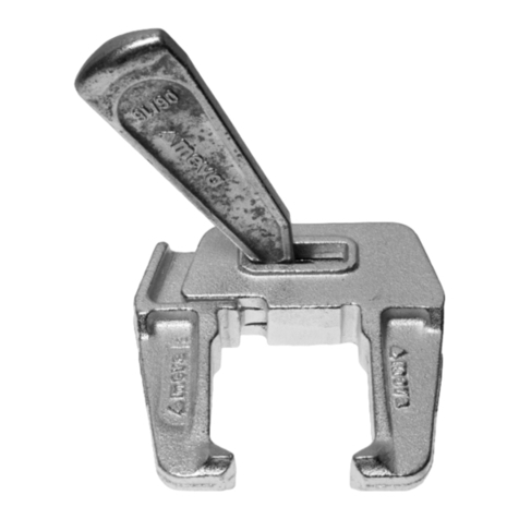
Meva MT 60 Owner's manual

Technical Instruction Manual
Shoring System MT 60

sbava.pdf St. 07/04/16 Printed in Germany
MT2
Shoring System MT 60
Abbreviations, measurements, figures and tables
The abbreviation MT is used for the MT 60 shoring system. Any
further abbreviations are explained where they are used the first
time.
Measurements: This manual uses the metric system and thus m (for
metre), cm (for centimetre) and mm (for millimetre). Dimensions
without a measure are in cm.
The page numbers in this manual start with MT. The figures
and tables are numbered per page. Depending on its product
abbreviation, a cross reference in the text refers to a page, table or
figure in this or in another manual.
Created: 7 April 2016
Product Features
The MT 60 shoring system is a square load tower sized 1.70 m by
1.70 m and allows for safe work in great heights. Fall down acci-
dents are avoided while work performance is increased. The maxi-
mum load capacity is 60 kN per tower post.
Achieve any tower height with only few parts
By using only few different standard parts, the tower can be assem-
bled to achieve almost any height. With the head spindle adjust-
able by up to 62 cm and the base spindle by up to 44 cm, only 3
frame heights (100, 75 and 50 cm) are sufficient to assemble almost
any tower height.
Safe assembly on the ground
The tower is safely assembled on the ground, either in vertical or
horizontal position. The scaffold platforms are self-locking and thus
can also be assembled with the tower in horizontal position.
Long life cycle, few cleaning and maintenance required
All parts are hot-dip galvanized, this results in a long life cycle as
well as minimized cleaning and maintenance efforts.

sbava.pdf St. 07/04/16 Printed in Germany
MT3
Shoring System MT 60
Please observe Contents
This Technical Instruction Manual contains information, instructions
and hints describing how to use the MEVA equipment on the con-
struction site in a proper, quick and economic way. Most examples
shown are standard applications that will occur in practice most
often. For more complicated or special applications not covered
in this manual, please contact the MEVA experts for advice. When
using our products the federal, state and local codes and regula-
tions must be observed. Many of the details shown do not illustrate
the wall formwork system in the ready-to-pour condition as to the
aforementioned safety regulations. Please adhere to this manual
when applying the equipment described here. Deviations require
engineering calculations and analysis to guarantee safety.
Please observe the assembly instructions that your local contractor
or employer has created for the site on which the MEVA equipment
is used. Such instructions are intended to minimise site-specific risks
and must contain the following details:
¢ The order in which all working steps including assembly and
disassembly must be carried out
¢ The weight of the panels and other system parts
¢ The type and number of ties and braces as well as the distance
between them
¢ The location, number and dimensions of working scaffolds
includ ing working area and protection against falling down
¢ Pick points for panel transport by crane. With regard to panel
tranport, please observe this manual. Any deviation will require a
static proof.
Important: Generally, only well maintained material may be used.
Damaged parts must be replaced. Apply only original MEVA spare
parts for replacement.
Attention: Never wax or oil assembly locks.
Product overview .................................................................................4
Integrated safety features ...................................................................6
Planking ................................................................................................7
Basic tower 170 x 170 – Vertical assembly .......................................... 8
Basic tower 170 x 170 – Horizontal assembly flat on the ground ...14
Tower 170 x 340 – Vertical assembly ................................................. 15
Working platform between two towers ..........................................19
Transport by crane .............................................................................20
Transport on wheels ...........................................................................21
Use with slab formwork MevaDec ...................................................22
Use with slab formwork MevaFlex ....................................................23
Disassembly ......................................................................................... 24
Height configurations from 2.51 to 6.42 m ......................................25
Height configurations from 6.84 to 8.46 m ......................................26
Height configurations from 9.65 to 12.54 m ....................................27
Material list – Tower heights from 2.01 to10.76 m .......................... 28
Material list – Tower heights from 10.16 to 18.66 m ....................... 29
Transport and storage ........................................................................30
Important work and handling rules .................................................. 31
Service .................................................................................................32

sbava.pdf St. 07/04/16 Printed in Germany
MT4
Shoring System MT 60
Product overview
The tower is fast and
safe to install.
The few different
parts can always be
assembled from a safe
platform.
Only 4 frames are
required per level.
Each frame has an
integrated ladder,
a crane eye and a
self-locking wedge con-
nection.
Frame 100 MT weighs
only 15.6 kg, all other
parts weigh less. This
eases assembly work.
The tower is compat-
ible with slab formwork
MevaDec and MevaFlex.
Each post has 60 kN
load capacity.
The entire tower can
be wheeled from posi-
tion to position if it does
not have more than
5 levels.
Zeichnung Nr. 300506_0006
Stand: 02.03.2016/bhe
bis
44 cm bis 62 cm
100 cm
17
0
170
Fig. 4.1 Shoring system MT 60
Access

sbava.pdf St. 07/04/16 Printed in Germany
MT5
Shoring System MT 60
Product overview
Zeichnung Nr. 300506_0006-1
Stand: 11.01.2016/bhe
Head spindle MT
Transport wheel MT
Base spindle MT
Horizontal brace MT
Ledger 170 MT
Access frame
100 MT
Basic frame 100 MT
Scaffold platform
170/68 with access
hatch MT
Toe board 170 MT
Fig. 5.1
Scaffold plat-
form170/30
The tower is always
assembled with the
same standard parts no
matter how high it is
and what it is used for.
Yet different accessories
can be mounted to the
head spindles to use the
tower to support slab
formwork or concrete
beams or prefab parts.

sbava.pdf St. 07/04/16 Printed in Germany
MT6
Shoring System MT 60
Integrated safety features
The shoring system is
equipped with a series
of features and func-
tions that maximize
safety when assembling,
using and transporting
the tower.
Detail 6.1.A
The two connectors in
the corner area can be
used for accessories or
other parts.
Detail 6.1.B
Each basic frame has a
crane eye.
Detail 6.1.C
Integrated ladder access.
Detail 6.1.D
Self-locking mechanism
at the connecting point
of the MT frames. The
high-tensile connection
allows the tower to be
crane-lifted.
Detail 6.1.E
Self-locking wedge con-
nection.
Zeichnung Nr. 300506_0008
Stand: 11.01.2016/bhe
Zeichnung Nr. 300506_0008_Detail_1
Stand: 08.03.2016/bhe
Zeichnung Nr. 300506_0008_Detail_2
Stand: 12.01.2016/bhe
Zeichnung Nr. 300506_0008_Detail_4
Stand: 13.01.2016/bhe
Detail 6.1.C
Detail 6.1.A
Detail 6.1.B
Detail 6.1.D
Detail 6.1.E
Fig. 6.1

sbava.pdf St. 07/04/16 Printed in Germany
MT7
Shoring System MT 60
Scaffold platform
Bez.: Gerüstbelag 170 / 68 mit Durchstieg
Art.-Nr.: 29-131-30
Gewicht: 14,1 kg
Stand: 04.02.2016
Bez.: Gerüstbelag 170 / 52,5
Art.-Nr.: 29-131-35
Gewicht: 11,1 kg
Stand: 04.02.2016
Bez.: Gerüstbelag 170 / 30
Art.-Nr.: 29-131-40
Gewicht: 8,0 kg
Stand: 04.02.2016
The scaffold platform is
made of wooden planks
inside an aluminium
frame. The maximum
load capacity is 200 kg/
m².
Note that scaffold plat-
forms are required on
every other tower level
so workers can safely
ascend and descend to
and from the tower.
The following scaffold
platforms are available
(the figures indicate
their length and width):
170/68 with access
hatch (Fig. 7.1)
170/30 and 220/30
(Fig. 7.2)
170/52,5 and 220/52,5
(Fig. 7.3)
Installation
The side of the scaffold
platform shown in Detail
7.1.A is plugged onto
the frame MT 100. The
self-locking mechanism
on the other end of
the scaffold platform
encloses the frame
on that end (Detail
7.1.B). The access hatch
(Detail 7.1.C) closes
automatically. All scaf-
fold platforms have a
grab handle on their
underside (Detail 7.2).
Fig. 7.1
Fig. 7.2 Fig. 7.3
Description Ref. No.
Scaffold platform 170/68
w/ access hatch ........... 29-131-30
Scaffold platform
170/52.5..................... 29-131-35
170/30........................ 29-131-40
220/52.5..................... 29-131-10
220/30........................ 29-131-15
Zeichnung Nr. 300506_0021
Stand: 16.02.2016/bhe
Zeichnung Nr. 300506_0022-1
Stand: 16.02.2016/bhe
Zeichnung Nr. 300506_0022-2
Stand: 26.02.2016/bhe
Zeichnung Nr. 300506_0022
Stand: 16.02.2016/bhe
Detail 7.1.A Detail 7.1.B Detail 7.1.C
Detail 7.2

sbava.pdf St. 07/04/16 Printed in Germany
MT8
Shoring System MT 60
Basic tower 170 x 170 – Vertical assembly
This page and the
following ones show
the vertical assembly of
a standard tower with
3 levels. For a description
of the horizontal assem-
bly see page MT-14. For
height configurations of
towers with more than
3 levels refer to paages
MT-25 through MT-27.
Ground
Check that the ground is
stable enough to sup-
port the tower.
Level 0
1. Start the assembly at
the highest point.
2. Place planks or
another load-distribut-
ing support for the base
spindles.
3. Place the 4 base spin-
dles MT on the planks or
support.
4. Connect the 4 ledg-
ers 170 MT with their
integrated wedges to
the base spindles MT
(Fig. 8.1).
5. Adjust the entire
assembly horizontally by
adjusting the base spin-
dles MT if and where
necessary. Make sure not
to exceed the maximum
spindle length of 44 cm.
6. Tighten the wedges
with a few hammer
blows (Fig. 8.1).
Level 1 (Fig. 8.2)
7. Standing on the
inside, plug the access
frame 100 MT onto the
base spindle at an angle
of 45° and turn it out-
wards until it locks.
Zeichnung Nr. 300506_0009-10
Stand: 15.01.2016/bhe
Zeichnung Nr. 300506_0009-9
Stand: 15.01.2016/bhe
Fig. 8.1
Fig. 8.2
Description Ref. No.
Base spindle MT .......... 29-129-50
Ledger 170 MT ........... 29-122-10
Access frame MT 100 . . 29-121-10
Basic frame 100 MT .... 29-120-10
Position at 45° and
turn outwards

sbava.pdf St. 07/04/16 Printed in Germany
MT9
Shoring System MT 60
8. Attach the frames
100 MT to the other
spindles the way you
attached the access
frame in Step 7 (Fig. 9.1).
9. Attach a horizontal
brace MT between two
frames MT 100 to make
sure the entire frame
construction is rectangu-
lar (Fig. 9.2).
10. Suspend the follow-
ing scaffold platforms
for level 0 at the ledgers
170 MT:
1 scaffold platform
170/68 with access hatch
3 scaffold platforms
170/30
Important
Always suspend the
scaffold platform 170/68
with access hatch in
a way that the access
hatch opens to frame
100 MT and you can
climb up or down the
ladder that is integrated
in the frame.
Level 2
11. Standing on the scaf-
fold platform of level 0,
suspend the frames 100
MT for level 2 (Fig. 9.3).
Zeichnung Nr. 300506_0009-8
Stand: 09.03.2016/bhe
Zeichnung Nr. 300506_0009-7
Stand: 15.01.2016/bhe
Description Ref. No.
Basic frame 100 MT .... 29-120-10
Horizontal brace MT ... 29-127-10
Scaffold platform 170/68
w/ access hatch ........... 29-131-30
Scaffold platform
170/30........................ 29-131-40
Fig. 9.1
Fig. 9.3
Zeichnung Nr. 300506_0009-8.1
Stand: 09.03.2016/bhe
Fig. 9.2
Basic tower 170 x 170 – Vertical assembly

sbava.pdf St. 07/04/16 Printed in Germany
MT10
Shoring System MT 60
12. Suspend the scaffold
platforms 170/30 for
level 1 (Fig.10.1).
13. Ascend to level 1
and suspend the scaffold
platform 170/68 with
access hatch (Fig.10.2)
Important
Always suspend the
scaffold platform 170/68
with access hatch in
a way that the access
hatch opens to frame
100 MT and you can
climb up or down the
ladder that is integrated
in the frame.
Zeichnung Nr. 300506_0009-6
Stand: 14.01.2016/bhe
Zeichnung Nr. 300506_0009-5
Stand: 14.01.2016/bhe
Fig. 10.1
Fig. 10.2
Basic tower 170 x 170 – Vertical assembly
Description Ref. No.
Basic frame 100 MT .... 29-120-10
Horizontal brace MT ... 29-127-10
Scaffold platform 170/68
w/ access hatch ........... 29-131-30
Scaffold platform
170/30........................ 29-131-40

sbava.pdf St. 07/04/16 Printed in Germany
MT11
Shoring System MT 60
Zeichnung Nr. 300506_0009-4
Stand: 14.01.2016/bhe
Zeichnung Nr. 300506_0009-3
Stand: 14.01.2016/bhe
Fig. 11.1
Fig. 11.2
Basic tower 170 x 170 – Vertical assembly
Description Ref. No.
Basic frame 100 MT .... 29-120-10
Horizontal brace MT ... 29-127-10
Scaffold platform 170/68
w/ access hatch ........... 29-131-30
Scaffold platform
170/30........................ 29-131-40
Level 3
14. Standing on the
scaffold platform of
level 1, install the frames
100 MT for level 3
(Fig. 11.1)
15. Remove the scaffold
platform with access
hatch from level 1 and
install it on level 2
(Fig. 11.2).
16. Descend to level 0.

sbava.pdf St. 07/04/16 Printed in Germany
MT12
Shoring System MT 60
17. Remove the from
level 1 and install them
on level 2 (Fig.12.1).
18. Climb up to level 2
using the ladder inte-
grated in frame MT 100
(Fig.12.2).
Zeichnung Nr. 300506_0009-2
Stand: 14.01.2016/bhe
Zeichnung Nr. 300506_0009-1
Stand: 13.01.2016/bhe
Fig. 12.1
Fig. 12.2
Basic tower 170 x 170 – Vertical assembly
Description Ref. No.
Basic frame 100 MT .... 29-120-10
Horizontal brace MT ... 29-127-10
Scaffold platform 170/68
w/ access hatch ........... 29-131-30
Scaffold platform
170/30........................ 29-131-40

sbava.pdf St. 07/04/16 Printed in Germany
MT13
Shoring System MT 60
Zeichnung Nr. 300506_0009
Stand: 14.01.2016/bhe
19. Plug the 4 head spin-
dles MT into the frame
posts and adjust them
(Detail 13.1.A)
20. Toe boards are
always installed at
the highest working
platform (Fig.13.1).
Attach the toe boards
170 MT as shown in
Fig. Detail13.1.B.
21. Attach the 4 trans-
port wheels MT to the
base spindles MT and to
the frames MT of level 1
(Fig.13.2 and Detail 13.2)
Important
Plankings for working
platforms need to be
installed on every second
level to allow for a safe
ascent and descent.
Attention
Depending on its
height and the load it
is exposed to, e.g. wind
load, the tower needs
to be anchored to an
existing building. Sev-
eral towers need to be
connected with diagonal
braces and ledgers. Fol-
low the details provided
by the stress analyst.
A
Zeichnung Nr. 300506_0011
Stand: 18.01.2016/bhe
A
Zeichnung Nr. 300506_0011
Stand: 18.01.2016/bhe
Fig. 13.1
Fig. 13.2Detail 13.2
Zeichnung Nr. 300506_0009_Detail_1
Stand: 09.02.2016/bhe
Detail 13.1.A
Zeichnung Nr. 300506_0009_Detail_2
Stand: 09.02.2016/bhe
Detail 13.1.B
Basic tower 170 x 170 – Vertical assembly
Description Ref. No.
Head spindle MT ......... 29-129-55
Toe board 170 MT ...... 29-126-15
Transport wheel MT .... 29-129-90

sbava.pdf St. 07/04/16 Printed in Germany
MT14
Shoring System MT 60
Basic tower 170 x 170 – Horizontal assembly flat on the ground
The horizontal assembly
on the ground is done
with the same material
and in the same way as
the vertical assembly. For
further details see the
cross-references to the
vertical assembly section.
Ground
The ground must be
flat to allow for a
trouble-free assembly
(Fig.14.1).
Level 0 and 1
(vertical assembly)
1. Assemble level 0 and 1
with frames 100 MT
and an access frame as
described on pages MT-8
and MT-9.
2. Turn the assembled
construction by 90°
(Fig. 14.1). Level 2 and
all other levels are now
assembled and added
horizontally and the
assembled tower will be
erected when all levels
have been added.
Level 2 until final
height (horizontal
assembly)
3. Assemble the frames
for all other levels –
always at an angle of
45° and from the inside
to the outside (Fig. 14.2).
4. Install scaffold plat-
forms including access
hatch on every other
level (Fig. 14.3). Since
the scaffold platforms
are self-locking, they will
not tilt or fall off.
5. Attach the head spin-
dles on the last tower
level (Fig. 14.4).
Erecting the tower
1. Attach 4-rope crane
slings to the crane eyes
of the top frame MT
(Fig. 14.5)
2. Erect the tower and
crane-lift it to its place
of use.
3. Align the tower hori-
zontally and vertically.
Attention
Depending on its
height and the load it
is exposed to, e.g. wind
load, the tower needs
to be anchored to an
existing building. Sev-
eral towers need to be
connected with diagonal
braces and ledgers. Fol-
low the details provided
by the stress analyst.
Zeichnung Nr. 300506_0037_1
Stand: 31.03.2016/bhe
Zeichnung Nr. 300506_0037_2
Stand: 31.03.2016/bhe
Zeichnung Nr. 300506_0037_3
Stand: 31.03.2016/bhe
Zeichnung Nr. 300506_0037-4
Stand: 31.03.2016/bhe
Fig. 14.1 Fig. 14.2
Fig. 14.3
Fig. 14.5
Fig. 14.4
Zeichnung Nr. 300506_0037-5
Stand: 31.03.2016/bhe

sbava.pdf St. 07/04/16 Printed in Germany
MT15
Shoring System MT 60
Zeichnung Nr. 300506_0010-11
Stand: 08.03.2016/bhe
Zeichnung Nr. 300506_0010-12
Stand: 09.02.2016/bhe
Zeichnung Nr. 300506_0010.1
Stand: 08.03.2016/bhe
Zeichnung Nr. 300506_0010-10
Stand: 08.03.2016/bhe
Fig. 15.1
Fig. 15.2
Fig. 15.3
Fig. 15.4
Tower 170 x 340 – Vertical assembly
Ground
Check that the ground is
stable enough to sup-
port the tower.
Level 0
1. Start the assembly at
the highest point.
2. Place planks or
another load-distribut-
ing support for the base
spindles.
3. Place the 4 base spin-
dles MT on the planks or
support.
4. Connect the 4 ledg-
ers 170 MT with their
integrated wedges to
the base spindles MT
(Fig. 15.1).
5. Adjust the entire
assembly horizontally by
adjusting the base spin-
dles MT if and where
necessary. Make sure not
to exceed the maximum
spindle length of 44 cm.
6. Tighten the wedges
with a few hammer
blows (Fig. 15.1).
Level 1 (Fig. 15.2)
7. Standing on the
inside, plug the access
frame 100 MT onto
the base spindle at an
angle of 45° and turn it
outwards until it locks
(Fig.15.2).
8. Attach the frames
100 MT to the other
spindles the way you
attached the access
frame in Step 7
(Fig. 15.3).
9. Attach a horizontal
brace MT between two
frames MT 100 to make
sure the entire frame
construction is rectangu-
lar (Fig. 15.3).
10. Suspend the follow-
ing scaffold platforms
for level 0 at the ledgers
170 MT:
2 scaffold platforms
170/68 with access hatch
6 scaffold platforms
170/30
Important
Always suspend the
scaffold platform 170/68
with access hatch in
a way that the access
hatch opens to frame
100 MT and you can
climb up or down the
ladder that is integrated
in the frame (Fig. 11.2
on page MT-11).
Level 2
11. Standing on the scaf-
fold platform of level 0,
suspend the frames 100
MT for level 2 (Fig. 15.4).
Description Ref. No.
Basic frame 100 MT .... 29-120-10
Horizontal brace MT ... 29-127-10
Scaffold platform 170/68
w/ access hatch ........... 29-131-30
Scaffold platform
170/30........................ 29-131-40

sbava.pdf St. 07/04/16 Printed in Germany
MT16
Shoring System MT 60
Zeichnung Nr. 300506_0010-9
Stand: 08.03.2016/bhe
Zeichnung Nr. 300506_0010-8
Stand: 08.03.2016/bhe
Zeichnung Nr. 300506_0010-7
Stand: 08.03.2016/bhe
Fig. 16.1
Fig. 16.2
Fig. 16.3
Tower 170 x 340 – Vertical assembly
12. Suspend scaffold
platforms 170/30 and
scaffold platform 170/68
with access hatch for
level 1 (Fig. 16.1).
13. Install ledger 170
MT und diagonal brace
170/100 MT to brace
both towers (Fig. 16.2).
Bracing with ledger
and diagonal brace is
required on each tower
level.
14. Suspend all other
scaffold platforms
170/30 in level 1.
15. Ascend to level 1
and suspend the scaffold
platform 170/68 with
access hatch (Fig. 16.3)
Important
Always suspend the
scaffold platform 170/68
with access hatch in
a way that the access
hatch opens to frame
100 MT and you can
climb up or down the
ladder that is integrated
in the frame (Fig. 12.2
on page MT-12).
Description Ref. No.
Basic frame 100 MT .... 29-120-10
Horizontal brace MT ... 29-127-10
Scaffold platform 170/68
w/ access hatch ........... 29-131-30
Planking 170/30 .......... 29-131-40
Ledger 170 MT ........... 29-122-10
Diagonal brace
170/100 MT ................ 29-125-25

sbava.pdf St. 07/04/16 Printed in Germany
MT17
Shoring System MT 60
Zeichnung Nr. 300506_0010-6
Stand: 08.03.2016/bhe
Zeichnung Nr. 300506_0010-4
Stand: 08.03.2016/bhe
Zeichnung Nr. 300506_0010-5
Stand: 08.03.2016/bhe
Fig. 17.1
Fig. 17.2
Fig. 17.3
Level 3
16. Standing on the
scaffold platform of
level 1, install the frames
100 MT for level 3
(Fig. 17.1).
17. Remove the scaffold
platforms from level 1
in one tower and sus-
pend them in level 2
(Fig. 17.2).
18. Install the bracing
between the two towers
(Fig. 17.3).
Tower 170 x 340 – Vertical assembly
Description Ref. No.
Basic frame 100 MT .... 29-120-10
Horizontal brace MT ... 29-127-10
Scaffold platform 170/68
w/ access hatch ........... 29-131-30
Scaffold platform
170/30........................ 29-131-40
Ledger 170 MT ........... 29-122-10
Diagonal brace
170/100 MT ................ 29-125-25
Fig. 16.2

sbava.pdf St. 07/04/16 Printed in Germany
MT18
Shoring System MT 60
Zeichnung Nr. 300506_0010-3
Stand: 18.01.2016/bhe
Zeichnung Nr. 300506_0010-1
Stand: 08.03.2016/bhe
Fig. 18.1
Fig. 18.2
19. Remove the scaffold
platforms from level 1
and install them on level
2 (Fig. 18.1).
20. Ascend to level 2
(Fig. 18.2).
21. Install toe boards
170 MT, head spindles
MT and the bracing
between the towers.
Attention
Depending on its
height and the load it
is exposed to, e.g. wind
load, the tower needs
to be anchored to an
existing building. Sev-
eral towers need to be
connected with diagonal
braces and ledgers. Fol-
low the details provided
by the stress analyst.
Tower 170 x 340 – Vertical assembly
Description Ref. No.
Basic frame 100 MT .... 29-120-10
Horizontal brace MT ... 29-127-10
Scaffold platform 170/68
w/ access hatch ........... 29-131-30
Scaffold platform
170/30........................ 29-131-40
Ledger 170 MT ........... 29-122-10
Diagonal brace
170/100 MT ................ 29-125-25

sbava.pdf St. 07/04/16 Printed in Germany
MT19
Shoring System MT 60
Working platform between two towers
Zeichnung Nr. 300506_0017
Stand: 30.03.2016/bhe
Zeichnung Nr. 300506_0017_2D
Stand: 30.03.2016/bhe
Description Ref. No.
Scaffold platform
170/52.5..................... 29-131-35
170/30........................ 29-131-40
220/52.5..................... 29-131-10
220/30........................ 29-131-15
Toe board
170 MT ....................... 29-126-15
220 MT ....................... 29-126-10
Platform railing
170 MT ....................... 29-128-15
220 MT ....................... 29-128-10
Ledger
170 MT ....................... 29-122-10
220 MT ....................... 29-122-15
Standard post 100 MT 29-123-10
Fig. 19.1
Fig. 19.2
A safe working or walk-
ing area between two
towers can be achieved
by installing either
scaffold platform 170 or
scaffold platform 220
and platform railing 170
or 220 respectively.
The railing is attached
to the frames 100 MT on
both sides (Fig. 19.1).
Make sure to plan and
install an access frame
100 MT towards the
platform in both towers
so that the platform can
be accessed from the
towers (Fig. 19.2).

sbava.pdf St. 07/04/16 Printed in Germany
MT20
Shoring System MT 60
Transport by crane
Zeichnung Nr. 300506_0020_Detail
Stand: 16.02.2016/bhe
Zeichnung Nr. 300506_0020
Stand: 16.02.2016/bhe
The entire tower is
transported in one lift.
The 4-rope crane slings
are attached to the
crane eyes of the frames
MT (Detail 20.1).
Detail 20.1
Fig. 20.1
Table of contents
Other Meva Construction Equipment manuals
Popular Construction Equipment manuals by other brands
hymer
hymer 6071 Instructions for use

Unimec
Unimec FG3T-35 Operating, maintenance, spare parts manual
Turbosol
Turbosol PRO H CL Instructions for use and maintenance

Jerr-Dan
Jerr-Dan MPL40 Operation and safety manual

MAGIC SCREED
MAGIC SCREED HD6060 Owner's manual & parts book

probst
probst SDH-H-15 operating instructions
