Meva Mammut XT Owner's manual

Technical Instruction Manual
Mammut XT

Mammut XTWall formwork
The Mammut XT wall formwork is a crane-dependent frame
formwork system made of hot-dip galvanised and post-treated
steel. It is ideal for use in high-rise, public, commercial and industrial
construction as well as civil engineering projects.
With its integrated combination tie hole recessed in the frame, the
system can be tied in three ways, both from one side and from
two sides, without needing to perform assembly or disassembly
measures on the panel. The option of choosing the tying method
best suited to the project significantly reduces the formwork placing
time. Furthermore, the combination tie hole enables the panels to be
stacked without having to remove parts beforehand.
The Mammut XT panel dimensions and the absolutely symmetrical
inner tie holes result in a uniform tie hole pattern and a uniform joint
pattern for the highest architectural-concrete requirements.
The Mammut XT panels are equipped with the 20mm thick alkus
facing made of polypropylene and aluminium. The facing is riveted to
the panel on the pouring side. In addition, the facings are protected
with silicone. The solid plastic facing has all the positive properties of
plywood plus important advantages: longer lifespan, greater load-
bearing capacity, better nail-holding ability, fewer and easier repairs,
100% recyclability.
The MEVA multi-function profile with welded-in DW-threaded nuts
makes the attachment of accessories easier, for example:
ÆPush-pull props and alignment rails with flange screws
ÆWalkway brackets with integrated self-locking pin
ÆDW tie rods of any length that are used to bridge problem areas.
The maximum permissible fresh-concrete pressure is 100kN/m² (when
using tie rods with a permissible working load of 160 kN), see page
XT-27. The fresh-concrete pressure for vertical formwork according
to DIN18218:2010-01 can be determined easily and precisely with
MEVA’s online concrete pressure calculator. This and other digital aids
are available in the download area at www.meva.net and in the app
MEVAme for iOS and Android.
Safety equipment
SecuritBasic was developed for the Mammut XT; this safety system
prevents falling accidents and at the same time increases occupational
safety and work eciency. For more information refer to the
SecuritBasic Technical Instruction Manual.
Abbreviations, measurements, figures and tables, etc.
The abbreviation XT is used for the Mammut XT. DIN means Deutsche
Industrie-Norm (German Industrial Standard). E DIN (E = Entwurf /
draft) means that the DIN is in draft status and not yet approved. Any
further abbreviations are explained where they are used for the first
time.
TÜV means Technischer Überwachungsverein. This is the independent
German organisation that tests the safety of technical installations,
machinery and motor vehicles. If a product passes the test, it is
permitted to carry the GS seal. GS stands for Geprüfte Sicherheit
(approved safety).
Measurements: This manual uses the metric system, i.e. m (for metre),
cm (for centimetre) and mm (for millimetre).
Non-defined dimensions are in cm.
The page numbers in this manual start with XT. The figures and tables
are numbered per page. Depending on its product abbreviation, a
cross reference in the text refers to a page, table or figure in this or in
another manual. This is indicated by the product code with which the
cross-reference begins.
Product features
XT-2 Technical Instruction Manual / Status August 2021

Mammut XTWall Formwork
Please note
Contents
This Technical Instruction Manual contains information, instructions
and tips that describe how to use the MEVA equipment on the
construction site in a proper, quick and economic way. Most examples
shown are standard applications that will occur in practice most
often. For more complicated or special applications not covered in this
manual, please contact the MEVA experts for advice. They will help
you without delay.
When using our products, the federal, state and local occupational
health and safety regulations must be observed. Please observe the
assembly instructions that your local contractor or employer has
created for the site on which the MEVA equipment is used. Such
instructions are intended to minimise site-specific risks and must
contain the following details:
ÆThe order in which all working steps including assembly and
disassembly must be carried out
ÆThe weight of the panels and other system parts
ÆThe type and number of ties and braces as well as the distance
between them
ÆThe location, number and dimensions of working scaffolds in-
cluding the working area and fall protection equipment required
ÆAttachment points for panel transport by crane. With regard to
panel transport, please observe this manual. Any deviation will
require structural verification.
Important: Generally, only well-maintained material may be used.
Damaged parts must be replaced. Use only original MEVA spare parts
for replacement.
Attention: Never wax or oil assembly locks!
Formwork assembly and stripping..................................................... 4
The Mammut XT panel ..................................................................... 8
Parking positions ............................................................................ 10
Overview of panels ......................................................................... 11
Free combination of vertical and horizontal panels.......................... 12
Tie hole and joint pattern................................................................ 13
alkus all-plastic facing..................................................................... 14
Panel connection ............................................................................ 15
Tying methods ................................................................................ 16
The combination tie hole ................................................................ 17
Sealing the combination tie hole..................................................... 18
Single-sided tying with XT tie rod DW 20 and plastic tube .............. 19
Single-sided tying with XT taper tie 20............................................ 21
Single-sided tying with XT taper tie 23............................................ 23
Single-sided tying with XT taper tie 20 or 23 .................................. 25
Two-sided tying with DW tie rod and plastic tube .......................... 26
Rules for concrete pouring and rate of placing................................ 27
Flatness of surface .......................................................................... 28
Attachment of accessories .............................................................. 29
Wall braces..................................................................................... 30
Workplaces..................................................................................... 33
Workplaces – SecuritBasic safety system......................................... 34
Workplaces – Folding access platform BKB 125 .............................. 35
Workplaces – Walkway bracket ...................................................... 36
Workplaces – Ladder fixture for wall formwork............................... 37
Workplaces – Tilting bracket 40/60................................................. 38
Crane Hook .................................................................................... 39
90° corner ...................................................................................... 40
90° corner – Single-sided tying ....................................................... 42
90° corner – Two-sided tying .......................................................... 43
90° corner – Inside corner .............................................................. 44
90° corner – Outside corner............................................................ 45
Hinged corner................................................................................. 48
Stripping corner.............................................................................. 50
Length compensation – Mammut XT compensation panel.............. 58
T wall connection ........................................................................... 61
Connection to existing walls ........................................................... 63
Wall offset...................................................................................... 64
Stop ends ....................................................................................... 65
Pilasters .......................................................................................... 67
Differences in height....................................................................... 68
Horizontal panels............................................................................ 69
Stabilisation of units ....................................................................... 70
Substitution of ties.......................................................................... 71
Crane ganging................................................................................ 73
Column formwork – With standard panels...................................... 75
Closing the tie holes ....................................................................... 76
Sealing the tie holes........................................................................ 77
Sealing the tie holes – FB active stop XT20 .................................... 78
Sealing the tie holes – Seal kit......................................................... 79
Overview of cones and plugs .......................................................... 80
Lifting hook 60 .............................................................................. 81
Single-sided formwork / climbing formwork ................................... 82
Transport ........................................................................................ 83
Services .......................................................................................... 84
Product list .................................................................................... 87
XT-3Technical Instruction Manual / Status August 2021

Mammut XTWall formwork
Formwork assembly and stripping
Fig. 4.1
Important!
When assembling and stripping
formwork, strictly observe the
local accident prevention rules.
When using our formwork and
systems always observe federal,
state and local codes and
regulations.
Attention
ÆDuring the entire assembly
and stripping process vertical
panels must be supported or
secured against toppling by
other means. This applies to all
panel types, hence also to corner
panels, curved panels, etc.
ÆAbove a formwork height
of 2.00 m both sides of the form-
work must be secured against
falling.
Planning
If you want to benefit fully from
the ecient and economical
use that the formwork offers,
we recommend you first plan
and prepare its use. Start
planning by determining the
optimum formwork quantity to
be held in stock (the quantity
is usually based on the amount
of formwork required for a one
day‘s work). When determining
the quantity, consider the
following:
ÆThe formwork weight
ÆThe time required for form-
work assembly and stripping
ÆTransport of gangs from
one pour to the next consider-
ably reduces assembly and strip-
ping effort and time
ÆCapacity of the lifting
devices
ÆA logical cycle plan that
takes corner configurations, rein-
forcements, etc. into account.
Once all these aspects have been
considered, the quantities of
formwork items can be specified.
Ground
The ground on which the
formwork is going to be
placed should be clean,
even and capable of bearing
the expected load, as this
will help reduce the time
required for the assembly and
stripping.
Panel transport
When unloading panels or
moving panel stacks, make
sure to use appropriate
transport devices that can
bear the load. For detailed
information see page
XT-81.
The steps required for
assembly
For ergonomic reasons
the outside formwork
(initial formwork) is usually
assembled and placed first.
Start assembly in a corner
or at a defined position and
perform the following steps:
Step 1 – Place and brace
the outside formwork (initial
formwork)
Step 2 – Define and mark the
pouring height, install the
reinforcements and boxouts
Step 3 – Place the inside
formwork (final formwork)
and tie the outside and inside
formwork
Refer to the following pages
for a detailed description
of these steps including the
installation of the working
platform and formwork
stripping.
Double-sided formwork
XT-4 Technical Instruction Manual / Status August 2021

Mammut XTWall Formwork
Fig. 5.1
Formwork assembly and stripping
Step 1
Place and brace the outside
formwork (initial formwork)
The following description is
based on an straight wall. Before
starting, keep in mind:
ÆWhen pre-assembling large
panel units on an even surface,
attach the wall braces and the
walkway bracket as well, i.e.
before performing step 1.
ÆWalls of less than 6m
require a filler in the inside form-
work for easy stripping (Fig. 5.3),
as the formwork may otherwise
become wedged and stick to the
concrete when it is stripped.
1. Spray the facing with the
release agent MevaTrenn pro.
2. Place the first panel and
immediately attach it to the
ground or concrete slab with
two brace frames to prevent it
falling over (Fig. 5.1). The foot
plate must be firmly connected
to the ground or concrete slab –
in earth with two ground pegs,
in concrete with two heavy-duty
dowels.
After placing vertical panels,
always reinforce them
immediately with push-pull
props or brace frames so they
can withstand tensile and
compressive forces and are
protected against displacement
and wind. The prop spacing is
determined by the application.
If the walkway bracket was not
pre-assembled before step 1, you
can now assemble and install the
working platform. Fig.6.2 on
page XT-6 shows a working
platform being lifted with a
crane for attachment to a braced
outside formwork.
Fig. 5.2
Fig. 5.3
Filler for easy stripping
3. String further panels together
and connect them with M
assembly locks (see page
XT-15).
Panels with a height of 350cm
are usually connected with three
assembly locks. However, outside
corner configurations require
four assembly locks (Fig.5.2).
Step 2
Pouring height,
reinforcements and boxouts
After performing step 1, the
pouring height is defined and
marked. Then the reinforcements
and boxouts, if required, are
installed.
Step 3
Place the inside formwork
(final formwork) and tie the
outside and inside formwork
The inside formwork is placed
after the outside formwork. The
inside and outside formwork are
then tied firmly with tie rods (for
the tying methods refer to page
XT-16).
Note
Correct set-up of the formwork
to the desired wall thickness is
facilitated by using a stop or
a mark on the ground which
allows the inside formwork to be
positioned exactly.
XT-5Technical Instruction Manual / Status August 2021

Mammut XTWall formwork
Formwork assembly and stripping
Working scaffold
The plug-in walkway bracket
is used to support the working
scaffold. The maximum bracket
spacing for a load of 150kg/
m² (platform group 2) is
2.50m as defined in DIN 4420.
The planking must be at least
4.5cm thick.
The planking and walkway
bracket can be firmly connected.
Do not install any planks before
securing the formwork with
push-pull props or before tying
the inside and the outside
formwork.
Do not forget to attach a side
railing to the working scaffold.
MEVA’s SecuritBasic safety
system offers platforms,
ladder access and other safety
equipment for safe and ecient
work at all heights (see page
XT-34).
Figures6.1 and 6.2 show the
folding access platform BKB 125
being used as a working scaffold.
Pouring concrete
Once you have placed, tied,
braced and closed the formwork,
you can start pouring concrete.
When doing so, observe the
permissible rate of placing taking
the setting behaviour and the
consistency of the cement into
account (see page XT-27).
Fig. 6.1
Fig. 6.2
XT-6 Technical Instruction Manual / Status August 2021

Mammut XTWall Formwork
Fig. 7.1
Fig. 7.2
Formwork assembly and stripping
Stripping
Do not start stripping before the
concrete has set to the point
where it can no longer deform.
It is best to start stripping at the
stop ends or at a short corner.
Start stripping with the inside
formwork. Stripping of both the
outside and inside formwork is
performed as follows:
1. Remove the tie rods section by
section. (for the tying methods
refer to page XT-16). Make
sure the unbraced formwork
is immediately secured to
prevent it falling over or strip it
immediately.
2. On the formwork panels or
large panel units the assembly
locks are removed at the joints,
and the panels or panel units
are then lifted out by hand or
by crane. Before transporting by
crane, the formwork must be
detached from the concrete!
3. Clean the facing and remove
any concrete. Before the next
use, spray the facing with the
release agent MevaTrenn pro
(for alkus facings). Observe the
operating instructions for the
alkus facing.
Note
The release agent must not be
stored in galvanized containers.
Please note
When stripping manually, detach
and disassemble the working
scaffold and the brace frames
before stripping the panels.
When transporting large panel
units with a crane, the working
scaffold and wall braces are
moved together with the
panel units. While vertical, all
components are cleaned and
sprayed with release agent
before being lifted together
to the next cycle (see pages
XT-73 and XT-74).
If there is no further use for the
panel units, the working scaffold
and wall braces are detached
and disassembled in a horizontal
position, and cleaned and
stacked for transport.
XT-7Technical Instruction Manual / Status August 2021

Mammut XTWall formwork
The Mammut XT panel
Fig. 8.2
The Mammut XT panel with
internal combination tie holes
(Fig.8.1).
Combination tie hole with
rotating sphere for single- and
two-sided tying (Fig.8.2).
Panel connection with the M
assembly lock in the continuous
groove (Fig.8.3).
Cross stiffener made of sturdy
closed steel profile with
welded-in DW15 threaded nuts
for fast and solid attachment of
accessories (Fig.8.4).
Transport hole to attach the
crane sling 60, allowing for fast
loading and unloading of panel
stacks or their relocation at
ground or slab level (Fig.8.5).
The steel frames are made of
closed hollow profiles with
welded-in mitred joints. The
profiles are provided with a
groove and edge protection.
Panels with a width of 100, 125
and 250 cm are equipped with
four bump notches (Fig.8.6)
that are welded in diagonally,
allowing exact panel positioning
without a hammer.
Note
For a list of the available panels
including their designations and
reference numbers refer to the
Product List.
Fig. 8.1
Fig. 8.3
Fig. 8.4
Fig. 8.5
Fig. 8.6
Mammut XT 350/125
XT-8 Technical Instruction Manual / Status August 2021

Mammut XTWall Formwork
The Mammut XT panel
Like all other Mammut XT
panels, the large MammutXT
350/250 panel (Fig.9.1) also has
internal tie holes. Thus, for the
forming area of 8.75m² only six
ties are required.
Besides internal combination
tie holes, the 75 and 50cm
MammutXT panels (Fig.9.2)
also have conical anchor sleeves
in the frame. This allows for
numerous formwork solutions,
especially at corners. DW tie rods
are used on both sides when
using the frame tie holes.
The alkus all-plastic facing in pre-
drilled in the area of the frame
tie holes and closed off with the
tie hole plug D27x20. The upper
tying positions of the 300 cm
high XT panels are closed off
with tie hole plugs D35x20 ex
works. The plugs simply have to
be removed to use the tie holes.
The plugs can be reused to close
the holes later.
Note
Unused tie holes must always be
closed with plug D35/38.
Fig. 9.2
Fig. 9.1
Internal combination tie hole
for single- and two-sided tying
Frame tie hole for two-
sided tying
Mammut XT 350/250
Mammut XT 350/75
and 350/50
Description Ref. No.
Tie hole plug
D27x20 ..................................29-902-78
D35x20 ..................................29-902-79
XT-9Technical Instruction Manual / Status August 2021

Mammut XTWall formwork
Parking positions
On the MammutXT panels
with widths 250 and 125cm
the assembly lock holders
are integrated into the cross
stiffeners (Figures10.1 and 10.2).
They serve as parking positions
for M assembly locks and Uni-
assembly locks.
The tie rod holder Ø35
(Figures10.3 and 10.4) can be
attached to the multi-function
profile of the vertical (Fig.10.1)
or horizontal MammutXT panel.
To install it, the tie rod holder
is turned by 45° (Fig.10.3),
inserted into the multi-function
nut and then turned back again.
It can hold up to two XT DW
tie rods, XT taper ties or DW tie
rods with articulated flange nut
(Fig.10.1).
Both holders ensure that the
assembly locks and tie rods
are secure during the moving
process.
Fig. 10.1
Fig. 10.2 Fig. 10.3 Fig. 10.4
Assembly lock holder
Installation of the tie rod
holder Ø35
Tie rod holder Ø35
Description Ref. No.
Tie rod holder Ø35 .................29-927-05
XT-10 Technical Instruction Manual / Status August 2021

Mammut XTWall Formwork
Overview of panels
Fig. 11.1
Tried-and-tested panels heights
and only a few panel widths
provide a comprehensive range
of widths and heights with
increments of 25cm (Fig.11.1).
250
125 300 350
25
5075
100
125
250
XT-11Technical Instruction Manual / Status August 2021

Mammut XTWall formwork
All Mammut XT panels can
be combined vertically or
horizontally (Figures 12.1 to
12.3). The ability to freely
combine all panels vertically or
horizontally allows for economic
width and height extension in
increments of 25 cm (Fig.12.3).
They must always be connected
with the Mammut assembly
lock (see page XT-15). The
continuous grooves on the
panels allow the assembly locks
to be positioned steplessly.
Free combination of vertical and horizontal panels
Fig. 12.1
Fig. 12.3
Fig. 12.2
25 25 25 25 25 25
XT-12 Technical Instruction Manual / Status August 2021

Mammut XTWall Formwork
Tie hole and joint pattern
Fig. 13.1
The MammutXT panel
dimensions and the symmetrical
internal tie holes result in a
uniform tie hole and joint pattern
for the highest architectural-
concrete requirements. This
applies to vertical, horizontal
or a combination of vertical
and horizontal formwork
(Figures13.1 and 13.2).
Fig. 13.2
Tie hole and joint pattern
250 125 100 75 50 25
25
50
75
100
125
250
350
XT-13Technical Instruction Manual / Status August 2021

Mammut XTWall formwork
alkus all-plastic facing
The tried-and-tested
polypropylene and aluminium
composite facing (Fig.14.3)
has all the positive properties
of plywood plus important
advantages: longer lifespan,
greater load-bearing capacity,
better nail-holding ability,
fewer and easier repairs, 100%
recyclability.
Besides the obvious advantages
such as considerably reduced
cleaning effort, minimum
consumption of release agent
and an excellent, uniform
concrete finish, alkus offers
substantial ecological benefits.
Substituting plastic for wood
saves valuable timber resources.
Also, alkus avoids the release
of highly toxic dioxin that is
released when burning plywood
bonded with phenolic resin.
Used or damaged alkus facings
can be recycled to produce
new facings. They are 100%
recyclable and subject to a global
return policy.
Fig. 14.1 Fig. 14.2
Fig. 14.3
Plastic layer
Metal or fibres
Foamed plastic core
Metal or fibres
Plastic layer
Frame profile with plywood facing:
Negative imprint in the concrete when using
panels with a conventional plywood facing
Frame profile with alkus facing:
Smooth and even concrete surface as there are no
projecting profiles
Design of the alkus all-plastic facing:
XT-14 Technical Instruction Manual / Status August 2021

Mammut XTWall Formwork
Fast and ecient connection
of the panels is accomplished
with the M assembly lock
(Fig.15.1) whether the panels
are assembled side by side or
on top of each other (height-
extended). The assembly lock can
be attached at any position on
the panel joint between the cross
stiffeners. Since it weighs only
3kg, it can be easily attached
with only one hand.
Its five-point contact (Fig.15.3)
draws the panels together and
aligns them. Secure connection
and perfect alignment are
achieved with only a few
hammer blows. The assembly
lock locks into a fail-safe position
immediately and automatically.
Panels with a height of 350cm
are connected with three
assembly locks. All other panels,
whether vertical or horizontal,
are connected with two
assembly locks.
When pouring architectural
concrete with SB3 quality
(German architectural concrete
class for immaculate architectural
concrete surface), panels that are
250cm high or higher require an
additional assembly lock.
Horizontal panel connections
generally require two assembly
locks.
For the quantity of assembly
locks required for outside corners
and columns refer to pages
XT-45 to -47 as well as
XT-75).
Panel connection
Fig. 15.1
Fig. 15.2 Fig. 15.3
= 5-point contact
Description Ref. No.
M assembly lock .....................29-400-71
XT-15Technical Instruction Manual / Status August 2021

Mammut XTWall formwork
Tying methods
The Mammut XT allows three
different tying methods:
ÆSingle-sided tying with XT
tie rod DW20 and plastic tube
(Fig.16.1)
ÆSingle-sided tying with XT
taper tie 20 (Fig.16.2) or 23
without plastic tube
ÆTwo-sided tying with DW
20 tie rod and plastic tube
(Fig.16.3)
The max. load is 160 kN for all
three types of tie rod.
Attention
Unused tie holes must always
be closed with plug D35/38 or
alternatively with XT sealing
cone with a pressed-on plugD20
(seepage XT-18).
Fig. 16.2
Fig. 16.1
Fig. 16.3
Single-sided tying with XT tie rod DW 20 and plastic tube
Two-sided tying DW 20 and plastic tube
Single-sided tying with XT taper tie 20 (or 23) without plastic tube
Description Ref. No.
XT tie rod DW 20/75...............23-154-35
XT tie rod DW 20/120.............29-154-40
Plastic tube D23/200.............. 29-902-31
Plastic tube D23/18................ 29-902-03
Plastic tube D23/23................ 29-902-04
Plastic tube D23/28................ 29-902-05
Plastic tube D23/33................ 29-902-06
XT taper tie 20/15-25 .............23-154-10
XT taper tie 20/20-30 .............23-154-15
XT taper tie 20/35-45 .............23-154-20
XT taper tie 23/15-25 .............23-154-60
XT taper tie 23/20-30 .............23-154-65
XT taper tie 23/35-45 .............23-154-70
XT taper tie 23/45-55 .............23-154-75
XT taper tie 23/60-70 .............23-154-80
XT sealing cone 5 AL20 ......... 29-902-34
XT sealing cone 10 AL20 ....... 29-902-35
XT cone DW 20 ..................... 29-902-37
Tie rod DW 20/120................ 29-900-97
Articulated flange nut 20/140 29-900-05
Plug D35/38 ...........................29-902-71
Einseitige Ankerung
mit XT-Ankerstab DW20 und Rillenrohr
Einseitige Ankerung
mit XT-Konusankerstab 20
Zweiseitige Ankerung
mit Ankerstab DW20 und Rillenrohr
XT-16 Technical Instruction Manual / Status August 2021

Mammut XTWall Formwork
The combination tie hole
Fig. 17.1
Fig. 17.4 Fig. 17.5
Tying method Initial formwork Final formwork
Single-sided with XT tie rod DW 20 and plastic tube Thread Anchor sleeve
Single-sided with XT taper tie 20 or 23 without
plastic tube Thread Anchor sleeve
Two-sided with DW tie rod and plastic tube Anchor sleeve Anchor sleeve
Table 17.6
The combination tie hole
(Fig.17.1) is a rotating
attachment point for XT tie rods
DW, XT taper ties and tie rods
DW.
It is recessed and firmly
integrated between the centre
profiles of the panel (Fig.17.1).
Depending on the tying method
selected (Table17.6 and page
XT-16), the sphere of the
combination tie hole can be
rotated by 90° to set it to
either a conical anchor sleeve
(Fig.17.4) or a DW20 thread
(Fig.17.5).
Setting it to the DW thread
(Fig.17.5 and Table.17.6)
replaces the articulated flange
nut on the formwork wall that
is installed first (initial formwork)
and allows single-sided tying.
The anchor sleeve (Fig.17.4
and Table17.6) is preset on the
initial-formwork side for two-
sided tying.
The combination tie hole is set
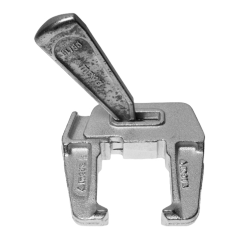
using the XT lever (Figures17.2
and 17.3).
Attention
As far as possible, tie rods are to
be placed in every combination
tie hole. In some cases tie rods
can be replaced, see pages
XT-71 and -72.
The karabiner hook on the XT
lever is for storage purposes only
and is not suitable for climbing.
Fig. 17.2
Fig. 17.3
Anchor sleeve
Thread
Description Ref. No.
XT combi lever........................23-154-90
XT-17Technical Instruction Manual / Status August 2021

Mammut XTWall formwork
Sealing the combination tie hole
Various cones are available to
seal the combination tie hole on
the facing side.
The XT sealing cone 5 AL20
is used for single-sided tying
(Fig.18.1).
All XT panels are delivered with
pre-assembled XT sealing cone
5 AL20 .
If a clearly visible shadow gap is
required, the XT sealing cone10
AL20 (Fig.18.2) is used for
single-sided tying.
If tying is performed from two
sides with DW tie rod and plastic
tube, the cone for plastic tube
D32 (Fig.18.3) is to be used.
The same cone is used on the
initial- and the final-formwork
sides.
To close unused combination tie
holes, e.g. in the corner area, the
plug D35/38 or alternatively the
XT sealing cone with pressed-on
plugD20 can be used (Fig.18.5).
The XT sealing cone can be easily
removed from the XT formwork
panel without causing damage
using the XT lever.
Description Ref. No.
XT sealing cone 5 AL20 ......... 29-902-34
XT sealing cone 10 AL20 ....... 29-902-35
Cone for plastic tube D32/10. 29-902-55
Plug D35/38 ...........................29-902-71
Plug D20, red......................... 29-902-63
Tying method XT sealing cone
5 AL20
XT sealing cone
10 AL20
Cone for plastic
tube D32
Single-sided with XT tie rod DW 20 and
plastic tube Yes Yes No
Single-sided with XT taper tie 20 or 23
without plastic tube Yes Yes No
Two-sided with DW tie rod and plastic
tube No No Yes
Fig. 18.1 Fig. 18.2 Fig. 18.3
Table 18.4
Fig. 18.5
Plug D35/38 XT sealing cone and
plug D20
XT-18 Technical Instruction Manual / Status August 2021

Mammut XTWall Formwork
Single-sided tying with XT tie rod DW 20 and plastic tube
Fig. 19.2
XT articulated flange nut
Plastic tube D23
Initial-formwork side:
Combination tie hole in
the thread position
Final-formwork side: Combination
tie hole in the anchor sleeve
position
The XT tie rod DW 20 is available
in various lengths for different
wall thicknesses.
XT tie rod:
ÆDW 20/75 for wall thickness
up to 40cm
ÆDW 20/120 for wall thick-
ness up to 85cm
The wall thickness is determined
by the length of the plastic tube.
The plastic tube must be 20mm
shorter than the desired wall
thickness (Fig.19.2).
Plastic tubes D23 are available
in the corresponding lengths for
wall thicknesses 20, 25, 30 and
35 cm (Table19.3).
Only the plastic tube D23/200
can be used.
When tying Mammut XT
formwork on one side only using
DW 20 tie rods (Fig.19.1) and
plastic tubes, the combination
tie holes in the initial-formwork
panels are set to the threaded
position and all other panels are
set to the anchor sleeve position
(Fig.19.2 and Table1717.6).
Seal all tie holes with the XT
sealing cone (Fig.19.2 and page
XT-18).
To correctly position the plastic
tube, press the XT cone DW20
on to the XT sealing cone on the
initial-formwork side.
Description Ref. No.
XT tie rod DW 20/75...............23-154-35
XT tie rod DW 20/120.............23-154-40
Plastic tube D23/200.............. 29-902-31
Plastic tube D23/18................ 29-902-03
Plastic tube D23/23................ 29-902-04
Plastic tube D23/28................ 29-902-05
Plastic tube D23/33................ 29-902-06
XT sealing cone 5 AL20 ......... 29-902-34
XT sealing cone 10 AL20 ....... 29-902-35
XT cone DW 20 ..................... 29-902-37
Fig. 19.1
Wall thickness (WT)
Long plastic tube = WT-20 mm
XT sealing cone
XT tie rod DW 20 with
integrated articulated flange nut
XT cone DW 20
Plastic tube D23
Pre-cut plastic tube Wall thickness (cm)
D23/18 20
D23/23 25
D23/28 30
D23/33 35
Table 19.3
XT cone DW 20 over
XT sealing cone
WAF 36
XT-19Technical Instruction Manual / Status August 2021

Mammut XTWall formwork
Assembly
Before pouring:
1. Press XT coneDW20 onto
the XT sealing cone on the
initial-formwork panel (Fig.20.1,
Sections 1 to 3.).
2. Place initial-formwork panel
(Fig.20.1 and XT-4 and-5)
and carry out boxout work
(Fig.20.2).
3. Place final-formwork panel
(Fig.20.3).
4. Install plastic tube D23 on the
XT tie rod DW 20. The length of
the plastic tube depends on the
wall thickness (see page XT-19).
5. Screw the XT tie rod DW 20
through the combination tie hole
of the final-formwork side into
the combination tie hole of the
initial-formwork panel (Fig.20.4)
using the 36 mm ratchet spanner.
An articulated flange nut is not
required on the initial-formwork
side.
6. Secure the XT tie rod DW 20
tightly by hand to the multi-
function nut of the formwork
panel using the fixation screw
integrated into the XT articulated
flange nut.
Disassembly
After pouring:
7. To strip the formwork, undo the
fixation screw on the XT tie rod
DW 20 and screw the tie rod out
of the combination tie hole of the
initial-formwork panel using the
36 mm ratchet spanner.
Single-sided tying with XT tie rod DW 20 and plastic tube
Fig. 20.4
Fig. 20.1
Fig. 20.2
Fig. 20.3
XT sealing cone
Description Ref. No.
XT tie rod DW 20/75...............23-154-35
XT tie rod DW 20/120.............23-154-40
Plastic tube D23/200.............. 29-902-31
Plastic tube D23/18................ 29-902-03
Plastic tube D23/23................ 29-902-04
Plastic tube D23/28................ 29-902-05
Plastic tube D23/33................ 29-902-06
XT sealing cone 5 AL20 ......... 29-902-34
XT sealing cone 10 AL20 ....... 29-902-35
XT cone DW 20 ..................... 29-902-37
Spanner size 36 ......................29-800-15
XT cone DW
20
1. 2.
3.
Notes
ÆCorrect set-up of the form-
work to the desired wall thick-
ness is facilitated by using a stop
or a mark on the ground which
allows the inside formwork to be
positioned exactly.
ÆThe XT tie rod DW can
be screwed in or out using the
flange nut ratchet spanner. The
width across flats is 36.
ÆWhen stripping, ensure that
the XT panel has been complete-
ly separated from the concrete
before lifting it with the crane.
XT-20 Technical Instruction Manual / Status August 2021
Other manuals for Mammut XT
1
Table of contents
Other Meva Construction Equipment manuals
