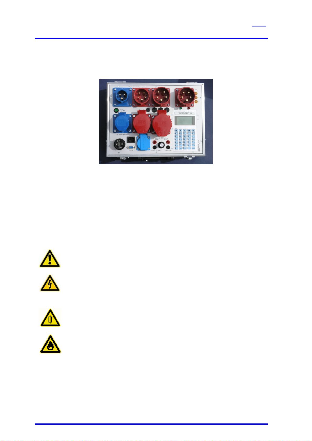
SAFETYTEST 3S Manual SAFETYTEST
SAFETYTEST GmbH 16 April 2006 Page 2 of 18
Contents
1General Warnings..................................................................................................4
2Application.............................................................................................................5
3Scope of Delivery..................................................................................................5
3.1 Standard: ...................................................................................................................5
3.2 Accessories (Optional): .............................................................................................5
3.3 Spare parts: ...............................................................................................................5
3.4 Software (Optional): ...................................................................................................5
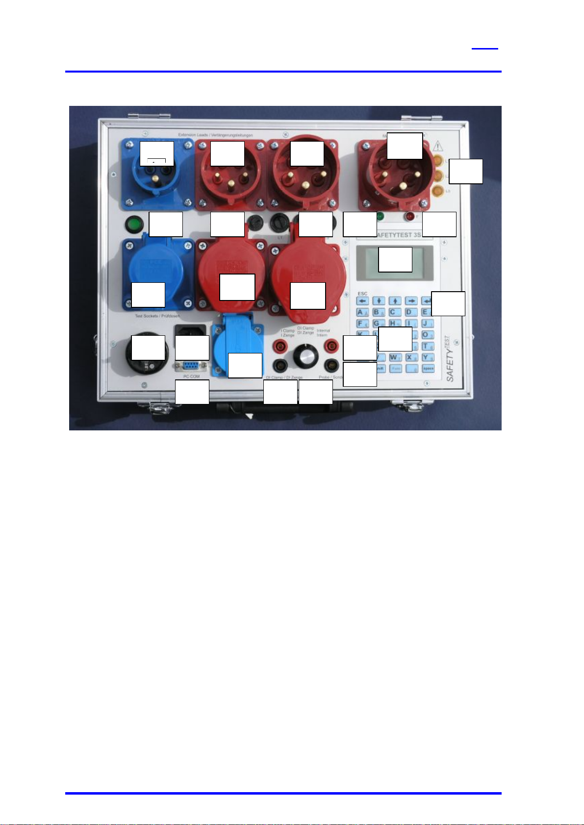
4Connections and user interface...........................................................................6
4.1 Connections (Picture 2)..............................................................................................7
4.2 Mains connection “Input“, Type CEE-32A 230/400V AC (Picture 2/1).........................7
4.3 Measuring socket “GND“ (Picture 2/16).....................................................................7
4.4 Measuring sockets “Probe“ (Picture 2/17) ..................................................................7
4.5 Interface PC-COM (Picture 2/18)................................................................................7
4.6 Test sockets (Picture 2/2,3,4)....................................................................................7
4.7 Testing plugs (picture 2/5,6,7)....................................................................................8
4.8 Fuses F1, F2 and F3 for all 16A testing sockets (picture 2/23)...................................8
4.9 Keyboard....................................................................................................................8
4.10 Display (Picture 2/14).................................................................................................8
4.11 Keyboard (Picture 2/15) .............................................................................................8
5Functional Description..........................................................................................9
5.1 Power supply..............................................................................................................9
5.2 Internal memory.........................................................................................................9
5.3 Interface RS232.........................................................................................................9
5.4 Display and Keyboard................................................................................................9
5.5 Fuses.........................................................................................................................9
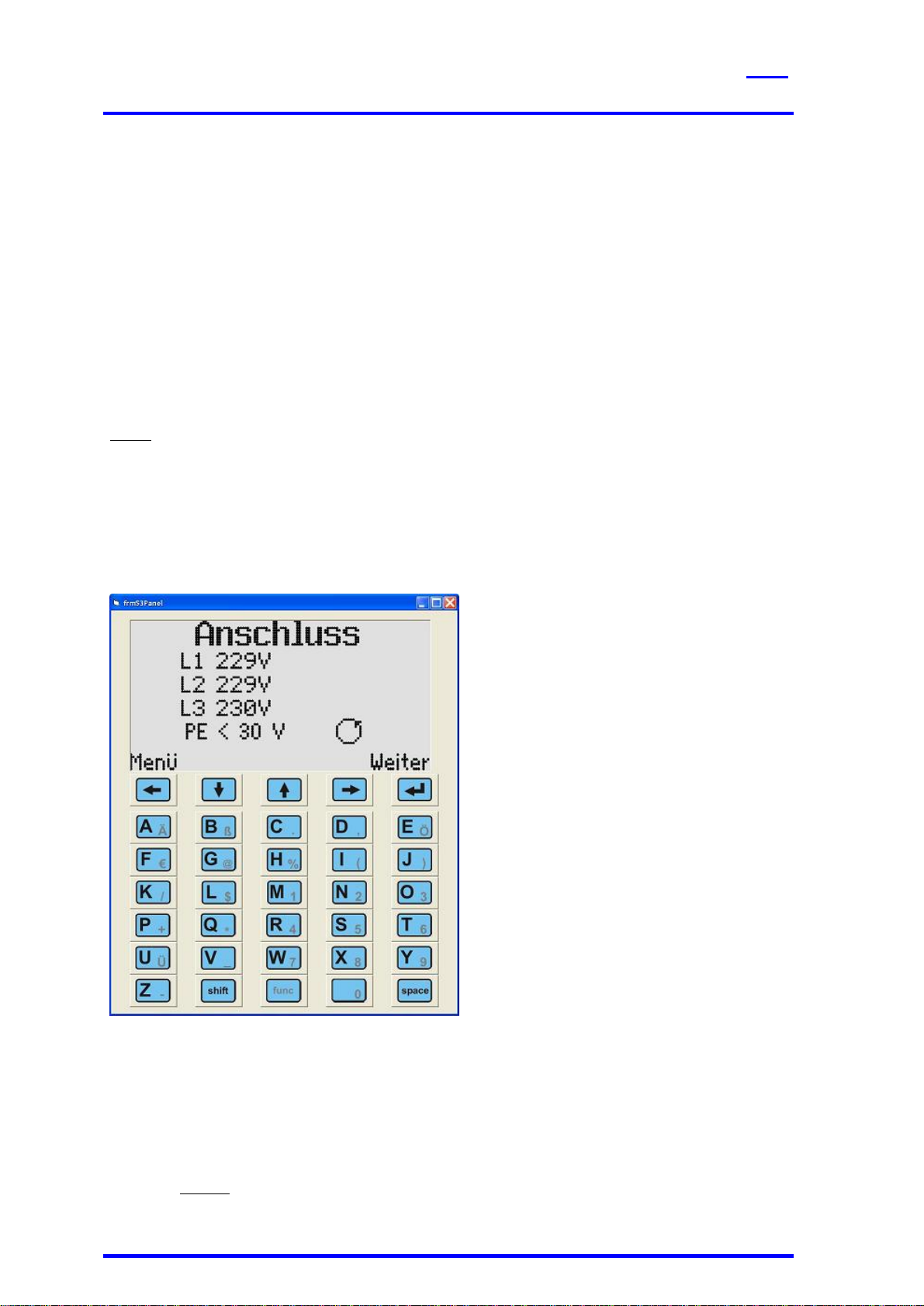
6Testing the Mains Connection............................................................................10
7Connection test...................................................................................................10
7.1 AC Supply................................................................................................................10
7.2 Three phase connection...........................................................................................11
8Display and Menu Structure...............................................................................11
9Taking the Tester into Operation........................................................................11
9.1 Visual check.............................................................................................................11
9.2 Connecting the tester to the mains system...............................................................11
9.3 Starting the test........................................................................................................11
10 Testing Electrical Appliances.............................................................................11
10.1 Qualification .............................................................................................................12
10.2 Mains connection.....................................................................................................12
10.3 Visual inspection......................................................................................................12
10.4 Measurements .........................................................................................................13
10.5 Functional test..........................................................................................................13
10.6 Checking the markings.............................................................................................13
10.7 Documentation of the test.........................................................................................13
11 Connections, Examples......................................................................................14
12 Updating the Firmware........................................................................................15
13 Error messages, removing faults.......................................................................16
13.1 The display remains dark .........................................................................................16
13.2 Touch current display is 0,000 mA ..........................................................................16
13.3 Touch current larger than 0,5 mA.............................................................................16