Acterna TestPad User manual
Acterna TestPad
Base Station & Air Interface Test Module (BAT)
Getting Started Guide

2
Wireless Networks Division
http://acterna.com/products/network_types/
wireless_networks/index.htm
Acterna’s Wireless Networks Division offers a wide range of so-
lutions for the testing of handsets, devices, RF and wireless net-
works. These solutions support carriers of wireless networks in
meeting their testing requirements. The maintenance of net-
works is made easier by optimizing operations, monitoring per-
formance and confirming billing accuracy. The mobile phone
industry uses Acterna’s solutions to accelerate production, de-
tect faults and check compliance. In a nutshell, users of the
Wireless Networks Division’s solutions gain real advantages
over their competitors.
Acterna is a world leader in mobile handset test equipment used
by service providers to determine specific problems with mobile
phones and validate the need for repair. Acterna’s Air Interface
Instruments and network systems are recognized leaders in
their field and are deployed around the world. Acterna’s R&D
labs are actively developing testing solutions for all of emerging
wireless services and networks.
NOTE
The information in this document has been carefully checked and is believed
to be entirely reliable. Acterna makes no warranty of any kind with regard to
the material in this document, and assumes no responsibility for any errors
which may appear in this document. Acterna reserves the right to make
changes without notice to any of its products to improve reliability,
performance or design.
Acterna assumes no responsibility for the use of any
circuitry other than circuitry which is part of a product of
Acterna. Acterna does not convey to the purchaser of
the product described herein any license under the
patent rights of Acterna nor the rights of others. All
product names as mentioned herein are the
trademarks or registered trademarks of their
respective companies.

3
Contents
Contents . . . . . . . . . . . . . . . . . . . . . . . . . . . . . . . . . . . . . . . 3
Introduction . . . . . . . . . . . . . . . . . . . . . . . . . . . . . . . . . . . . . 5
The Base Station & Air Interface Test Module (BAT) . . . . . . 6
About this manual . . . . . . . . . . . . . . . . . . . . . . . . . . . . . . . . . 6
Safety instructions . . . . . . . . . . . . . . . . . . . . . . . . . . . . . . . . . 6
Unpacking the BAT . . . . . . . . . . . . . . . . . . . . . . . . . . . . . . . 7
Standard equipment delivery . . . . . . . . . . . . . . . . . . . . . . . . 7
Acterna TestPad 2000TM (V3) delivery . . . . . . . . . . . . . . . . . 8
Dual-band coupler delivery . . . . . . . . . . . . . . . . . . . . . . . . . . 8
Connecting Acterna TestPad 2000TM with the BAT Module . 9
Elements of Acterna TestPad 2000TM and BAT . . . . . . . 10
Power LEDs . . . . . . . . . . . . . . . . . . . . . . . . . . . . . . . . . . . . 11
Handle with pocket for stylus . . . . . . . . . . . . . . . . . . . . . . . 11
Table for absolute power and reflection . . . . . . . . . . . . . . . 12
Connectors . . . . . . . . . . . . . . . . . . . . . . . . . . . . . . . . . . . . . 13
Slot for PCMCIA cards . . . . . . . . . . . . . . . . . . . . . . . . . . . . 14
Printer port . . . . . . . . . . . . . . . . . . . . . . . . . . . . . . . . . . . . . 14
Switches and connectors . . . . . . . . . . . . . . . . . . . . . . . . . . 15
Battery slot . . . . . . . . . . . . . . . . . . . . . . . . . . . . . . . . . . . . . 15
Three Main Applications for Using the BAT . . . . . . . . . . 16
Application 1:
Measurements at the base station’s attenuated output . . . 16
Application 2:
Measurements using a coupling device . . . . . . . . . . . . . . . 18
Application 3:
Measurements over the air interface . . . . . . . . . . . . . . . . . 20
Working With the User Interface . . . . . . . . . . . . . . . . . . . 22
Most important display sections . . . . . . . . . . . . . . . . . . . . . 23
Application buttons . . . . . . . . . . . . . . . . . . . . . . . . . . . . . . . 23
System buttons . . . . . . . . . . . . . . . . . . . . . . . . . . . . . . . . . . 25
Online help screen . . . . . . . . . . . . . . . . . . . . . . . . . . . . . . . 26

4
Up- and Downloading Configuration Data and Reports 27
Service and Calibration . . . . . . . . . . . . . . . . . . . . . . . . . . 27
Federal Communications Commission (FCC) Notice . . 28
Industry Canada Notice . . . . . . . . . . . . . . . . . . . . . . . . . . 28
Publication History . . . . . . . . . . . . . . . . . . . . . . . . . . . . . . 31

5
Introduction
Dear User of the Acterna TestPad
Base Station & Air Interface Test Module (BAT),
We hope that you will enjoy using the BAT as much as we
enjoyed designing it for you.
Your feedback on this test instrument is always welcome. It
enables us to improve the BAT through updates and upgrades.
So your feedback can be the first step towards an improved ver-
sion of the BAT! Send us your comments; you can reach us by
email, fax or via our local sales offices.
Additional information, hints and updates on the latest software
can be accessed online: www.acterna.com.
Your BAT Team
Support Europe/Asia
Tel: +49 89 99641-386
Fax: +49 89 99641-440
email: EuroWireSupport@acterna.com
Support Americas
Tel: +1 800 245 6356
+1 317 788 9351
Fax: +1 317 614 8347
email: [email protected]

6
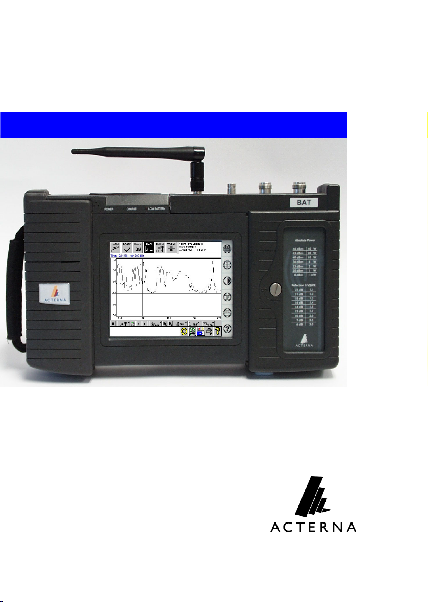
The Base Station & Air Interface Test Module
(BAT)
The BAT Module is a handheld RF spectrum meter based on
the Acterna TestPad 2000TM platform. Base stations can be
tested while in operation, without any shut down. You can test a
base station either at its RF output connector or over the air
interface. Simple use and a small size make testing easier than
ever.
About this manual
The Getting Started Guide supplements the complete operating
manual. It should be read before installing the BAT Module and
taking it into operation. Further instructions are contained in the
operating manual which is included with the BAT Module in the
form of detailed online help.
This booklet will provide you with initial information and guide
you up to the point where you will be able to retrieve more
detailed information from the online help.
The main sections of this manual advise you
• how to unpack and install the BAT Module
• about the main applications
• about the highest menu level of the user interface
• how to retrieve more help from the built-in online help
Safety instructions
Maintenance and repair is only allowed for specially trained ser-
vice technicians. Opening a unit without permission causes loss
of warranty.
See “Service and Calibration” on page 27 and the Federal Com-
munication and Industry Canada Notices on page 28.
7
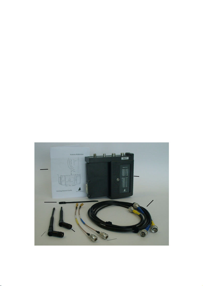
Unpacking the BAT
Keep the cardboard box for shipping the BAT back to Acterna
for recalibration and inspection (recommended once a year).
Standard equipment delivery
a 1 Base Station & Air Interface Test Module (BAT)
b 2 RF cables, N-type on N-type connectors, 2 m (ca. 6 ft.)
long, one with a blue cap and one with a yellow cap
c 2 RF adapter cables, N-type to SMA connectors, one
marked blue, one marked yellow
d 1 high-band antenna (not included in the cellular version)
e 1 low-band antenna, indicated by a cap with two colored
rings (not included in the PCS version)
f 4 removable cable binders
g This Getting Started Guide
a
b
f
c
d
e
g
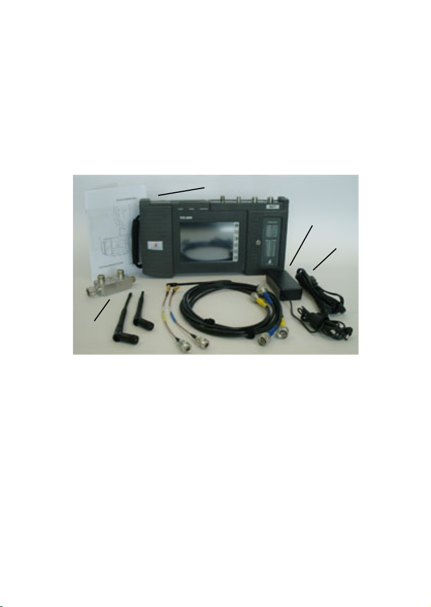
Acterna TestPad 2000TM (V3) delivery
Note: If the BAT Module has been ordered with the Acterna
TestPad 2000TM, the latter is delivered in the same main box.
The TestPad comes with a Getting Started Guide of its own;
please refer to this when unpacking and installing the TestPad.
The complete tester consists of the BAT Module and the
Acterna TestPad 2000TM. The latter consists of the following:
a User Interface Module
b Power supply
c Power cord
Dual-band coupler delivery
d 30 dB bidirectional dual-band coupler (max. 500 W)
a
b
c
d
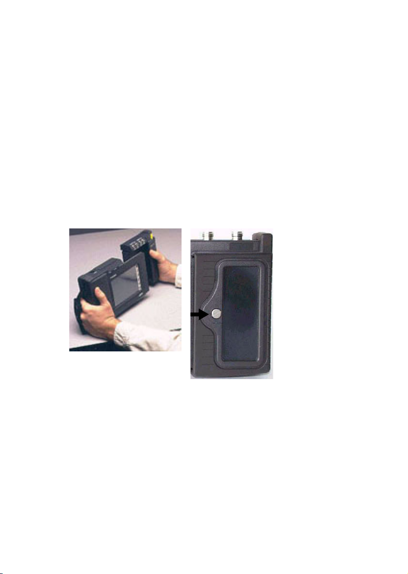
Connecting Acterna TestPad 2000TM with the
BAT Module
• The Acterna TestPad 2000TM may contain another applica-
tion module. If so, remove that other module.
• Slide the BAT Module into the Acterna TestPad 2000TM.
• Tighten the screw with a coin.
• Power on the TestPad.
• The application software will be downloaded from the BAT
Module (this will take a few minutes).
• Your BAT starts operation and is ready for use.
Please read the following pages carefully and do not forget
to charge the battery before going out in the field!

Elements of Acterna TestPad 2000TM and
BAT
Apart from the large touchscreen right in the middle, the Acterna
TestPad 2000TM with the BAT Module consists of the following
user elements:
a Power LEDs
b Connectors
c Table for absolute power and reflection
d Switches and connectors
e Battery slot
f Handle with stylus pocket
g PCMCIA card slot and printer port
The components above are explained and illustrated in
more detail on the following pages.
b
c
d
e
f
ga
Table of contents
Other Acterna Test Equipment manuals


