Meyer's 3465 User manual

Page 1 MODEL: 3465
INSTRUCTION AND PARTS BOOK NO. 10-18-11
HEAVY DUTY MANURE SPREADERS
MODEL: 3465
DO NOT
operate this Spreader until you have read
this book
NEVER
repair or clean this Spreader while PTO is
engaged
Manufactured in DORCHESTER, WISCONSIN by
MEYER’S EQUIPMENT
MFG. CORP.
Part Numbers E00017-E2415

MODEL: 3465 Page 2
INTRODUCTION
Congratulations on the purchase of your new Meyer’s
Manure Spreader. With its optional equipment this is
the simplest, most flexible system on the market to-
day. With proper operation and preventative mainte-
nance it will last for years.
This SAFETY ALERT SYMBOL means AT-
TENTION! BE CAREFUL! YOUR SAFETY IS IN-
VOLVED! It stresses an attitude of HEADS UP FOR
SAFETY. When you see this symbol, be alert to the
possibility of PERSONAL INJURY and carefully read
the message that follows.
WARNING:
NEVER OPERATE WITHOUT ALL COVERS,
SHIELDS AND GUARDS IN PLACE. KEEP HANDS,
FEET AND CLOTHING AWAY FROM MOVING
PARTS. SOME COVERS AND GUARDS HAVE
BEEN REMOVED FOR ILLUSTRATIVE PURPOSES
ONLY IN THIS MANUAL. FAILURE TO HEED MAY
RESULT IN SERIOUS PERSONAL INJURY OR
DEATH.
At the front of this manual is a Product Registration
and Inspection Certificate. Be sure your dealer has
completed this certificate and forwarded a copy to the
manufacturer to validate the manufacturer’s warranty.
The product model and serial number are recorded
on this certificate for your convenience and for proper
identification of your spreader by your dealer and the
manufacturer when ordering repair parts.
The serial number plate is found on the front center
of the spreader, just below the Implement PTO shaft.
For information on ordering repair parts, refer to the
repair parts section of this manual. Orders must list
the complete description, correct part number, and
total amount required.
All references to right hand and left hand apply to the
product as viewed from the rear of the machine and
facing the direction of forward travel.
You are urged to study this manual and follow the
instructions carefully. Your efforts will be repaid in
better operation and service as well as a savings in
time and repair expense. Failure to read this manual
and understand the machine could lead to serious
injury. If you do not understand instructions in this
manual, contact either your dealer or Meyer’s Equip-
ment Manufacturing Corp. at Dorchester, WI 54425.
This supercedes all previous published instructions.

Page 3 MODEL: 3465
TABLE OF CONTENTS
INTRODUCTION ............................................................................................................................................................................ 2
SAFETY.......................................................................................................................................................................................... 4
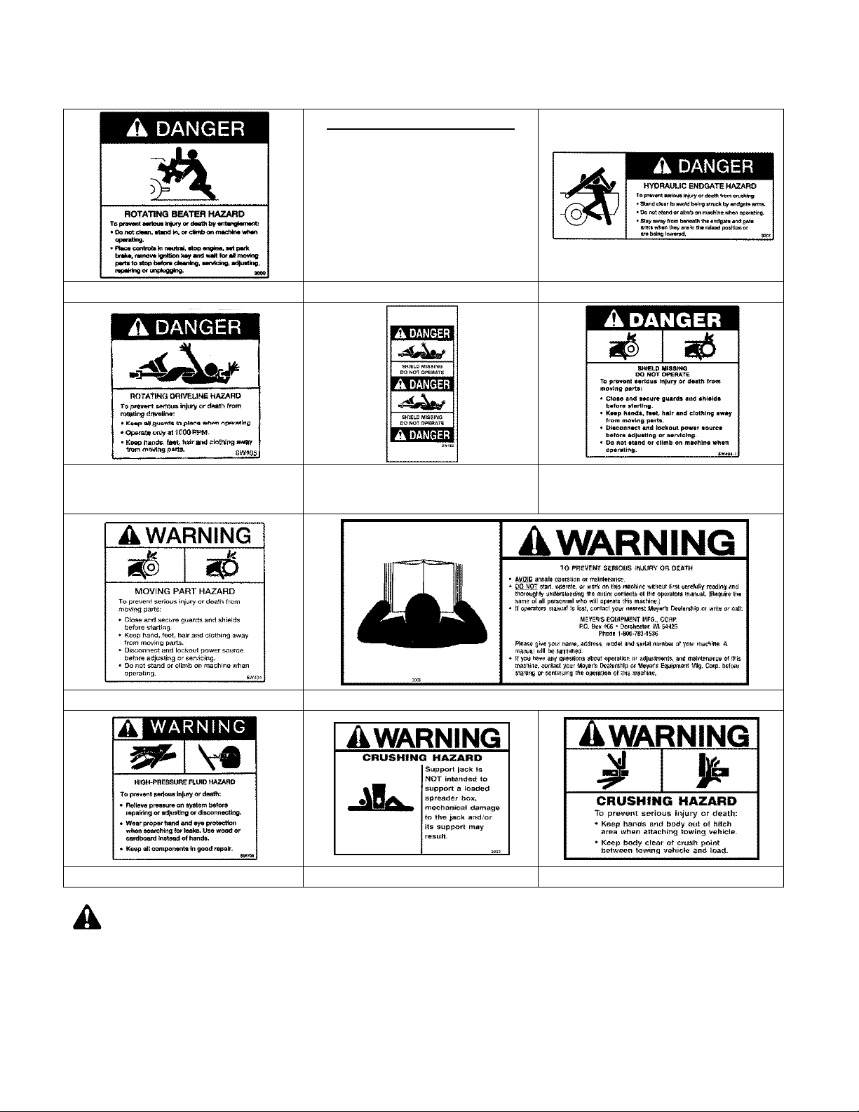
SAFETY SIGNS.............................................................................................................................................................................. 6
MANURE SPREADER SAFETY..................................................................................................................................................... 8
PRE-OPERATION ........................................................................................................................................................................ 10
General..................................................................................................................................................................................... 10
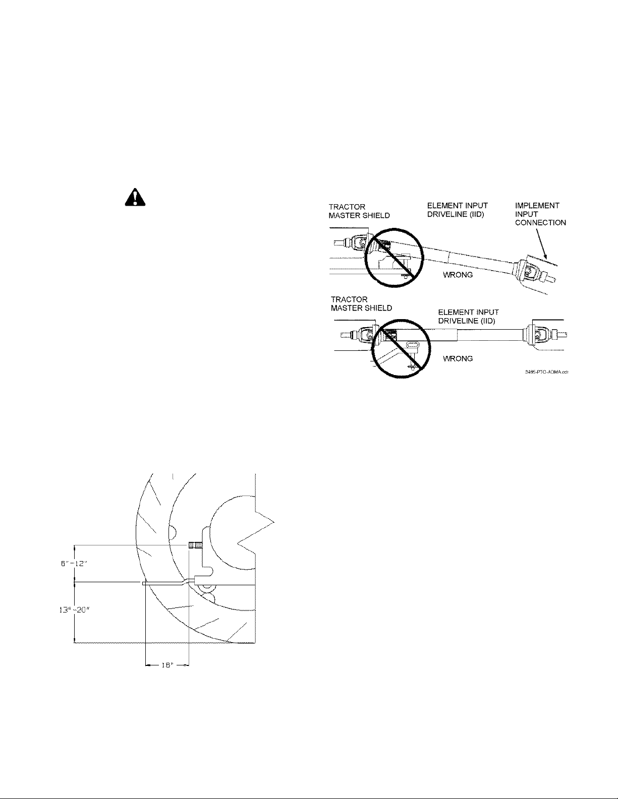
Tractor Hitch And PTO Requirements ...................................................................................................................................... 10
ADMA Recommendations: ....................................................................................................................................................... 10
Tractor Size Requirements ....................................................................................................................................................... 11
Tractor Towing Size Requirements....................................................................................................................................... 11
Material Estimated Weight Per Cubic Foot........................................................................................................................... 11
Hydraulic System...................................................................................................................................................................... 11
General................................................................................................................................................................................. 11
Set Up for Open Or Closed Center Hydraulic Operation ...................................................................................................... 12
Electric Control Installation ................................................................................................................................................... 12
Transporting ............................................................................................................................................................................. 13
General................................................................................................................................................................................. 13
Use Safety Chain.................................................................................................................................................................. 13
Use Lights............................................................................................................................................................................. 13
OPERATION ................................................................................................................................................................................ 14
Tractor Hookup......................................................................................................................................................................... 14
Loading..................................................................................................................................................................................... 14
Unloading ................................................................................................................................................................................. 15
Mandatory Safety Shutdown Procedure ................................................................................................................................... 15
MAINTENANCE, ADJUSTMENTS & LUBRICATION................................................................................................................... 16
Automatic Over Running Clutch
..................................................................................................................................................... 16
Mandatory Safety Shutdown Procedure
......................................................................................................................................... 16
Adjustments.............................................................................................................................................................................. 16
Apron Chain.......................................................................................................................................................................... 16
Roller Chain Adjustment....................................................................................................................................................... 16
Tensioning V-Belt Drive ........................................................................................................................................................ 16
Lubrication ................................................................................................................................................................................ 17
Cleaning And Storage............................................................................................................................................................... 19
REPAIR PARTS ........................................................................................................................................................................... 20
Main Frame & Box Parts........................................................................................................................................................... 20
Hydraulic End Gate & Related Parts......................................................................................................................................... 22
Jack Assembly.......................................................................................................................................................................... 24
End Gate Hydraulic Piping........................................................................................................................................................ 26
Axles, Wheels, Spindles And Related Parts ............................................................................................................................. 28
Side Drive Train........................................................................................................................................................................ 30
Apron & Related Parts .............................................................................................................................................................. 32
Lube Bank ................................................................................................................................................................................ 34
Beaters & Related Parts ........................................................................................................................................................... 36
Front Drive Train....................................................................................................................................................................... 38
Beater Drive Train..................................................................................................................................................................... 40
E00344-05 540 RPM Beater Drive Gear Box ........................................................................................................................... 42
5490-0686 540 RPM Beater Drive Gear Box Complete ........................................................................................................... 44
Upper Beater Drive................................................................................................................................................................... 46
Model 3465 Apron Drive Gearbox ............................................................................................................................................ 48
Removable CV Telescoping Universal Joint Assembly With Over Running Automatic
Clutch & Guard, Trailer To Tractor............................................................................................................................................ 50
Removable CV Telescoping Universal Joint Assembly with Over Running Automatic
Clutch & Guard, Trailer to Tractor............................................................................................................................................. 51
Standard Hydraulic Apron-Flow Control On Spreader And Optional Electric Control ............................................................... 52
Optional Tractor Lever Operated Hydraulic Apron.................................................................................................................... 54
Chain Oiling Kit......................................................................................................................................................................... 56
Standard Highway Lighting With Amber Side Light .................................................................................................................. 57
LIMITED WARRANTY STATEMENT ........................................................................................................................................... 60

MODEL: 3465 Page 4
SAFETY
A brief definition of signal words that may be used in
this manual:
DANGER: Indicates an imminently hazardous
situation that, if not avoided, will result in serious inju-
ry or death.
WARNING: Indicates a potentially hazardous
situation that, if not avoided, could result in death or
serious injury, and includes hazards that are exposed
when guards are removed.
CAUTION: Indicates a potentially hazardous
situation that, if not avoided, may result in minor or
moderate injury.
DECALS ARE ILLUSTRATED
ON PAGES 6 & 7.
CAUTION: IF ANY SAFETY SIGN BECOMES UNREADABLE FOR ANY REASON, THE SIGN MUST BE
REPLACED WITH A NEW SIGN. IF THE SPREADER IS REPAINTED, ALL SAFETY SIGNS MUST BE RE-
PLACED. CONTACT YOUR DEALER OR MEYER’S EQUIPMENT MANUFACTURING CORP. IF YOU RE-
QUIRE ANY SHIELD OR SIGNS FOR REPLACEMENT.

Page 5 MODEL: 3465
DECALS ARE ILLUSTRATED ON PAGES 6 & 7.
CAUTION: IF ANY SAFETY SIGN BECOMES UNREADABLE FOR ANY REASON, THE SIGN MUST BE
REPLACED WITH A NEW SIGN. IF THE SPREADER IS REPAINTED, ALL SAFETY SIGNS MUST BE RE-
PLACED. CONTACT YOUR DEALER OR MEYER’S EQUIPMENT MANUFACTURING CORP. IF YOU REQUIRE
ANY SHIELD OR SIGNS FOR REPLACEMENT.

MODEL: 3465 Page 6
SAFETY SIGNS
TENSIONING V-BELT DRIVE
1. Ideal tension is the lowest tension at which the
belt will not slip under peak load conditions.
2. Check tension frequently during the first 24-48
hours of operation.
3. OVER TENSIONING SHORTENS BELT AND
BEARING LIFE.
4. Keep belts free from foreign material which may
cause slip.
5. Make V-drive inspection on a periodic basis.
Tension when slipping- 1 to 2 full turns on eyebolt
nut at a time until slipping is not noticed. Never
apply belt dressing as this will damage the belt
and cause early failure.
DECAL A. PART NO. 3000 DECAL B. PART NUMBER 3012 DECAL C. PART NO. 3001
DECAL D
PART NO. SW105 (FOR 1000
RPM)
DECAL E. PART NO. SW102 DECAL F. PART NO. SW404-1
DECAL G. PART NO. SW404 DECAL H. PART NO. 3006
DECAL I. PART NO. 700 DECAL J. PART NO. 3003 DECAL K. PART NO. 3004
CAUTION: IF ANY SAFETY SIGN BECOMES UNREADABLE FOR ANY REASON, THE SIGN MUST BE REPLACED
WITH A NEW SIGN. IF THE SPREADER IS REPAINTED, ALL SAFETY SIGNS MUST BE REPLACED. CONTACT YOUR
DEALER OR MEYER’S EQUIPMENT MANUFACTURING CORP. IF YOU REQUIRE ANY SHIELD OR SIGNS FOR RE-
PLACEMENT.

Page 7 MODEL: 3465
SAFETY SIGNS
DECAL L. PART NO. SW406 DECAL M. PART NO. SW2001
DECAL N. PART NO. SW2000
DECAL O. REFECTIVE TAPE RED
PART NO. PM17-5915
DECAL P. REFLECTIVE TAPE
-
YELLOW
PART NO. PM17-5910 DECAL Q. PART NO. 3009
START UP PROCEDURE
1. Make certain everyone is clear of machine before starting engine or
operation.
2. Turn Flow Control to Slowest Position.
3. Engage P.T.O.
4. RAISE END GATE.
5. Engage Tractor Hydraulic Lever to Full Flow Position.
6. Start Apron by Rotating Flow Control Dial Clockwise.
DECAL R. PART NO. 3008 DECAL S. PART NO. 3011
CAUTION: IF ANY SAFETY SIGN BECOMES UNREADABLE FOR ANY REASON, THE SIGN MUST BE
REPLACED WITH A NEW SIGN. IF THE SPREADER IS REPAINTED, ALL SAFETY SIGNS MUST BE RE-
PLACED. CONTACT YOUR DEALER OR MEYER’S EQUIPMENT MANUFACTURING CORP. IF YOU REQUIRE
ANY SHIELD OR SIGNS FOR REPLACEMENT.

MODEL: 3465 Page 8
MANURE SPREADER SAFETY
CAUTION
THERE ARE INHERENT HAZARDS ASSOCIATED WITH THE OPERATION OF A MANURE SPREADER.
FOR YOUR SAFETY:
•Never Enter Spreader Box While In Operation For Any Reason.
•Only Properly Instructed People Should Operate The Spreader. Do Not Allow Children Or Inexperienced Per-
sons To Operate Spreader.
•Keep All Guards And Shields In Place. Moving Parts Can Crush And Dismember.
•Clear The Area Before Equipment Start Up.
•Keep Hands, Feet, And Loose Clothing Away From Moving Parts.
•Do Not Go Near The Spreader Beaters While Machine Is Operating.
•Make Sure The PTO Is Securely Locked To Both The Tractor And Spreader Before Operating The Unit.
•Do Not Operate The PTO At Speeds Higher Than The Manufacturers Recommendations.
•Highway Traffic Is Not To Exceed 20 Mph. The Tires Supplied Are For Farm Use Only And Are Not Designed
For Use Above This Speed Unless Equipped With High Speed Highway/Off-road Farm Tires.
•Use Adequate Safety Chains When Towing The Spreader.
•The Use Of A Slow moving Vehicle Sign Is Required On All Public Roads Unless Equipped With Flashing
Hazard Lights. Obey All Applicable Highway Safety Laws And Rules.
•Always Use A Tractor Large Enough To Provide Sufficient Braking Assistance When Towing A Loaded
Spreader.
•Use Caution When Traveling Over Uneven Terrain And When Approaching Stops.
•Do Not Load The Spreader Unless It Is Hitched To The Tractor.
•Do Not Unhitch A Loaded Spreader From The Tractor Leaving It Supported By Only The Jack.
•Park Your Spreader On Level Ground And Place Blocks Ahead Of And Behind The Wheels Before Unhooking
From Tractor To Avoid Unexpected Rolling When Separated From The Tractor.
•Do Not Allow Riders on Spreader.
FAILURE TO HEED MAY RESULT IN SERIOUS PERSONAL INJURY OR DEATH
CAUTION
THERE ARE ADDITIONAL HAZARDS ASSOCIATED WITH THE SERVICE AND MAINTENANCE OF YOUR
SPREADER.
FOR YOUR SAFETY:
•Inspect When First Delivered And Regularly Thereafter; That All Connections And Bolts Are Tight And Secure
Before Operating.
•Retighten All Wheel Bolts After The First Hour Of Towing. Check Periodically Thereafter. See Maintenance,
Wheels.
•Maintain Proper Tire Air Pressure At All Times. See Maintenance, Tires.
•Always Wear Eye Protection When Operating Or Servicing Spreader.
•Be Sure All Movement Has Stopped, The PTO Is Disconnected, The Tractor Is Shut Off And The Ignition Key
Is Removed Before Servicing The Spreader Or Components.
•Escaping Hydraulic Fluid Under Pressure Can Penetrate The Skin And Cause Serious Injury. Relieve All Pres-
sure From The Hydraulic System Before Connecting Or Disconnecting The Lines Or Making Repairs. Check All
Hoses And Fittings Before Start-up And Periodically During Operation.
•Never Make Any Alterations Or Modifications To This Equipment.
FAILURE TO HEED MAY RESULT IN SERIOUS PERSONAL INJURY OR DEATH

Page 9 MODEL: 3465
MANDATORY SAFETY SHUTDOWN PROCEDURE
BEFORE unclogging, cleaning, adjusting, lubricating or servicing the unit:
1. Disengage the tractor PTO.
2. Shut off the tractor engine, remove the ignition key and take it with you.
3. Wait for all movement to stop.
4. Remove the Telescoping PTO Drive and ALL power connections from the tractor.
ONLY when you have taken these precautions can you be sure it is safe to proceed. Failure to follow the above
procedure could lead to death or serious bodily injury.
Most farm accidents, like industrial, home and high-
way accidents, are caused by the failure of some in-
dividuals to observe simple and fundamental safety
rules or precautions. For this reason farm accidents,
just as other types of accidents, can be prevented by
recognizing the causes of accidents and doing some-
thing about them before an accident occurs.
Regardless of the care used in the design and con-
struction of farm equipment, there are many points
that cannot be completely safe-guarded without inter-
fering with accessibility and efficient operation.
A careful operator is the best insurance against an
accident.
The complete observance of one simple rule would
prevent many thousand serious injuries each year.
That rule is “NEVER ATTEMPT TO CLEAN, OIL,
OR ADJUST A MACHINE WHILE IN MOTION”.
NATIONAL SAFETY COUNCIL
BEFORE ATTEMPTING TO OPERATE YOUR NEW SPREADER BE SURE TO READ THIS OWNERS MANUAL
AND FAMILIARIZE YOURSELF WITH THE MACHINE!! OBSERVE THE PRECAUTIONS IN THIS MANUAL FOR
SAFE OPERATION OF THIS MACHINE!!

MODEL: 3465 Page 10
PRE-OPERATION
GENERAL
Read the entire Owner's Manual before attempting to
operate this manure spreader. Before attempting any
maintenance or repairs; always be sure all rotating
parts have stopped and that the tractor is shut off,
disconnect the PTO, relieve all hydraulic pressure
and disconnect hydraulic hoses.
WARNING
NEVER OPERATE SPREADER WITH ANY
GUARDS OR SHIELDS REMOVED. FAILURE TO
HEED MAY RESULT IN SERIOUS PERSONAL IN-
JURY OR DEATH.
1. Completely lubricate the unit as described in the
LUBRICATION Section.
2. Check and tighten the wheel lug nuts if required.
3. Check and maintain the tire pressure according
to the manufacturer’s recommendation.
4. Check the entire unit for loose bolts, damaged or
loose hydraulic fittings and hoses or other dam-
aged parts.
5. The tractor half of the PTO drive shaft assembly
must be locked securely to the tractor output
shaft.
TRACTOR HITCH AND PTO REQUIRE-
MENTS
FIGURE 1. TRACTOR DRAWBAR & PTO
SPECIFICATION
The spreader is designed to be operated by a 1000
RPM PTO tractor output.
The PTO drive shaft assembly is designed to operate
with tractors conforming to the industry standard
shown on Figure 1 for 1000 RPM PTO output.
ADMA RECOMMENDATIONS:
FIGURE 2.
A tractor drawbar equipped with a clevis hitch (ham-
mer-strap) can cause interference with the PTO
driveline IID (implement input driveline). This interfer-
ence can cause serious damage to the IID or the IID
telescoping members. The clevis hitch on the tractor
must be removed.
If the implement (Figure 2, top view) is attached to a
tractor with a clevis hitch (hammer-strap) style draw-
bar, the hammer-strap must be removed to prevent
damage to the IID guarding or the IID telescoping
members.
If the implement (Figure 2, lower view) is attached to
a tractor with an offset in the drawbar, be certain it is
in the down position to prevent damage to the IID
guarding or the IID telescoping members.

Page 11 MODEL: 3465
TRACTOR SIZE REQUIREMENTS
The spreader does not have brakes. Towing the
spreader must be done safely. The ASAE (American
Society of Agricultural Engineers) specifies that the
towing vehicle should weigh at least 2/3 as much as
the loaded implement to be reasonably safe towing at
speeds up to 20 mph. This (20 mph) is also the max-
imum recommended towing speed for the spreader.
The loaded weight of your spreader will naturally vary
with the moisture of the manure and you must con-
sider that for your conditions. The loaded weight ca-
pacities as specified by the spreader manufacturer
are as follows:
Tractor Towing Size Requirements
Use the following chart for calculating the minimum
tractor weight.
MODEL
(struck
level)
SPREADER EMPTY
WEIGHT + LOAD =
GW
MINIMUM
TRACTOR
WEIGHT UP TO
20 MPH
3465
(308 ft
3
)
7000 + _____ = _____ 2/3 of spreader
gross weight
Material Estimated Weight Per Cubic Foot
Material
lbs / Cu. Ft.
Lime Sludge 110-115 LBS.
Dry Feedlot Manure 63-65 LBS.
Chicken Litter 63-65 LBS.
Cake Sludge 62-65 LBS.
Semi-Solid Manure 58-60 LBS.
Pen Packed Manure 30-35 LBS.
Liquid Manure 63-65 LBS.
SOURCE: ASAE
NOTE: HEAPED LOADS HAVE SIGNIFICANTLY
HIGHER CAPACITIES RESULTING IN INCREASED
WEIGHT AND HIGHER CENTER OF GRAVITY,
REQUIRING EXTRA PRECAUTION DURING OP-
ERATION.
HYDRAULIC SYSTEM
General
There are two hydraulic circuits on the spreader.
1. One circuit powers the hydraulic end gate.
2. The second circuit powers the hydraulic apron
drive. A check valve is installed in this circuit to
prevent operating the apron in reverse.
Therefore, the tractor requires two sets of remote
ports, one set for the hydraulic apron drive and one
set for the hydraulic end gate.
Three types of hydraulic operating systems are avail-
able for the apron drive on the spreader.
1. The standard operating system has an adjustable
flow control valve on the spreader which is man-
ually controlled by twisting a “control hose” which
is connected to the flow control valve on the
spreader and the opposite end of the hose is fit-
ted with a handle for the operator to operate from
the tractor seat. See Figure 3.
FIGURE 3. ST ANDARD APRON CHAIN
FLOW CONTROL
2. An optional electric control is available to replace
the “control hose” described above. This system
has a motorized flow control valve on the
spreader and an electric control box placed on
the tractor is used to control this valve. See Fig-
ure 4.

MODEL: 3465 Page 12
3. A third available system utilizes tractor lever flow
control. This system requires that the tractor have
an adjustable flow control lever (rabbit/turtle) op-
erated valve. There is no adjustable flow control
valve on the spreader when this option is pur-
chased for the spreader.
Set Up for Open Or Closed Center Hydraulic Op-
eration
1. Most late model tractors use a closed center hy-
draulic system which only pumps oil as required.
Some other tractors may have an open center
system which pumps oil continuously, in which
case provision must be made to allow excess
flow back to the tractor reservoir. If you are not
sure of your system, contact your tractor dealer.
2. Spreaders with standard or electric control are
shipped from the factory, set up for open center
tractors. To convert for a closed center, close the
ball valve by rotating the handle perpendicular to
the valve as illustrated on Figure 5.
3. Spreaders with tractor lever operated flow con-
trol (no flow control valve or ball valve on spread-
er) are shipped from the factory, set up for closed
center. If you require an Open Center, then a
field conversion must be made as illustrated on
Figure 6.
NOTICE! For tractors with closed center system and
load sensing that has a priority flow circuit that is
manually adjustable, the ball Valve must be open.
This is not a tractor lever operated system.
FIGURE 5. APRON FLOW CONTROL (OP-
TIONAL ELECTRIC ILLUSTRATED)
FIGURE 6. CONVERTING TRACTOR LEVER
OPERATED FLOW CONTROL TO OPEN
CENTER
Electric Control Installation
1. Locate the controller on the tractor where it is ac-
cessible to operate.
FIGURE 4. OPTIONAL ELECTRIC FLOW
VALVE CONTROLLER

Page 13 MODEL: 3465
2. Connect the electrical leads to the tractor 12VDC
power source, Figure 5.
3. When hooking up the spreader, connect the con-
troller to the motorized flow control valve at the
twist lok connector.
TRANSPORTING
General
Check for traffic constantly. Be sure you can see that
no one is attempting to pass you and that all traffic is
sufficiently clear from you before making any turns.
WARNING
BE SURE THE SLOW MOVING VEHICLE SIGN IS
INSTALLED ON THE REAR OF THE SPREADER
FOR TRANSPORTING ON ROADWAYS. KEEP
THIS SIGN AND ALL REFLECTIVE DECALS
CLEAN. FAILURE TO HEED MAY RESULT IN SE-
RIOUS PERSONAL INJURY OR DEATH.
CAUTION:
REGULARLY CLEAN OFF THE REFLECTIVE TAPE
AT THE REAR AND SIDES OF THE SPREADER
WHEN TRANSPORTING IT ON THE HIGHWAY.
WARNING
DO NOT TOW AT SPEEDS GREATER THAN 20
MPH. FAILURE TO HEED MAY RESULT IN SERI-
OUS PERSONAL INJURY OR DEATH.
Operating speed is dictated by the terrain over which
you are traveling. Always use caution. Avoid traveling
on slopes or hills that are unsafe. Also beware of
slippery conditions such as traveling over areas pre-
viously spread with manure. If possible, avoid
spreading over areas where manure has been previ-
ously applied.
If you will travel on public roadways and it is legal to
do so, you must know all rules governing such opera-
tion. This will include lighting and brake requirements
in addition to traffic rules. You may also be required
to install a safety chain on the spreader.
Use Safety Chain
CAUTION:
A SAFETY CHAIN SHOULD BE INSTALLED TO
RETAIN THE CONNECTION BETWEEN TRACTOR
(OR OTHER TOWING VEHICLE) AND SPREADER
WHENEVER TRAVELING ON PUBLIC ROADS. A
SUGGESTED ATTACHMENT IS ILLUSTRATED ON
Figure 7.
The chain must be strong enough to hold the weight
of the loaded spreader. If using a grab hook at the
end(s) of the chain to secure the chain to itself, a
hook latch must be installed.
The length of the safety chain is not to be any longer
than necessary to turn without interference. If any
chain links or attachment hardware are broken or
stretched, repair before using. Store chain so it does
not corrode or become damaged. Do not use this
chain for other implements because the strength and
length of chain may not be adequate. Identify this
chain for use on this particular spreader.
Safety chain designed for this spreader can be or-
dered on page 20.
Use Lights
Optional lights are offered for your spreader. Lights
are recommended for any spreader operated on pub-
lic roads and may be a requirement.
If equipped with lights, plug the electric plug into the
tractor trailer electrical receptacle.
FIGURE 7. SUGGESTED SAFETY CHAIN
INSTALLATION

Page 14 MODEL: 3465
OPERATION
DANGER
NEVER ENTER THE SPREADER BOX FOR ANY
REASON WITHOUT FIRST DISCONNECTING PTO
SHAFT FROM TRACTOR. DO NOT ALLOW OTHERS
IN THE BOX. ROTATING BEATER CAN DISMEMBER
OR KILL.
TRACTOR HOOKUP
FIGURE 8. SPREADER HOOK UP
CAUTION
DO NOT USE JACK EXCEPT WHEN SPREADER IS
EMPTY. JACK WILL NOT SUPPORT ADDED
WEIGHT FROM LOAD. UNBALANCED WEIGHT MAY
RESULT IN UNEXPECTED “TIP UP” OF THE
SPREADER.
1. Hook the spreader hitch to the tractor drawbar with
1 3/8” secured hitch pin.
2. Raise the jack off the ground. Remove the jack hub
pin and rotate the jack to horizontal storage posi-
tion and secure with the pin, Figure 8.
3. Connect the PTO drive shaft to the tractor PTO
output shaft and be sure it is locked to the tractor
shaft.
4. Connect the two hydraulic hoses for the apron drive
to a set of remote ports on the tractor. These are
the two hoses coming from the hydraulic flow con-
trol valve and apron drive hydraulic motor.
NOTE: The return line on the spreader has a check
valve in it so that the apron cannot be operated in the
wrong direction. This line must be connected to the
tractor return port. If the hoses are reversed, the apron
will not operate and the hoses should be switched.
5. Connect the two hydraulic hoses for the end gate to
a second pair of tractor remote ports.
6. If you have a standard hydraulic system equipped
spreader, locate the manual apron flow control
“twist” hose on the tractor where it can be operated
from the tractor seat.
7. If you have an optional electric control system, plug
the twist lok connectors together. See Figure 5 for
mounting instructions.
8. If you have an optional tractor lever operated sys-
tem there are no control hook ups required.
LOADING
FIGURE 9. HYDRAULIC END GATE, VIEW
FROM REAR
1. Check that the end gate is closed, Figure 9. When
the spreader is parked for loading, shift the tractor to
neutral or park and set the brakes. The moisture con-
tent of the manure will determine how full the spreader
can be loaded so that no manure spills out.
2. You will probably be able to load solid manure at
least level with the top of the box while semi liquid and
liquid slurries will have to be less than full in the
spreader box.

Page 15 MODEL: 3465
NOTICE! It is unlawful to allow slurry to splash or leak
onto public roads.
UNLOADING
DANGER
KEEP AWAY AND KEEP OTHERS CLEAR OF RO-
TATING BEATERS AT REAR OF SPREADER. SERI-
OUS INJURY OR AMPUTATION COULD RESULT.
WARNING
MAKE CERTAIN EVERYONE IS CLEAR OF EQUIP-
MENT BEFORE APPLYING POWER. FAILURE TO
HEED MAY RESULT IN SERIOUS PERSONAL INJU-
RY OR DEATH.
The rear beaters have been designed and tested to
provide the best spread pattern for most liquids and
semi solid manure. However, the pattern will vary for
each specific condition. The factors that contribute
most to differing patterns will be moisture content and
the amount and length of bedding material. For most
typical conditions, the spread pattern should be uniform
and about 30 feet wide or more for cattle manure and
about 20 feet wide for poultry manure. Plan your
spreading patterns so you do not have to travel over
previously spread manure which will be slippery, result-
ing in poor traction. Traction on wet grass is also poor.
When the resulting pattern may require that you over-
lap during spreading, use precautions on slopes and
hills where you will experience a loss of traction by
traveling over ground with previously spread manure.
CAUTION
DO NOT OPERATE APRON CHAIN WITHOUT RAIS-
ING END GATE FIRST. FAILURE TO HEED MAY RE-
SULT IN EQUIPMENT DAMAGE.
1. When you are ready to begin spreading application
on the field, open the hydraulic end gate, Figure 9,
and slowly engage the tractor PTO clutch. This can
be done while traveling forward to avoid a heavier
application at the edge of the field than desired.
The end gate must be completely open.
2. Once the end gate has been fully opened and the
PTO is up to speed, engage the apron drive (apron
chain).
3. For solid manure, start the apron at a slow rate of
speed.
4. Start the apron drive with the tractor hydraulic spool
valve lever.
5. For standard flow control systems, use the “twist”
hose to regulate the apron speed, Figure 8.
6. For optional electric control systems, turn the elec-
tric controller to “ON”. Turn the knob CW to in-
crease or CCW to decrease application rate. Re-
turn switch to “OFF” when spreading is completed,
Figure 4.
7. For tractor lever flow control systems, regulate the
apron speed with the tractor hydraulic system ad-
justable flow control, i.e., hydraulic rabbit/turtle
speed control lever.
8. Start application onto the field. Increase the speed
of apron chain for a heavier application.
NOTICE! DO NOT FEED FROZEN MANURE AT A
RATE TOO FAST. THE APRON DRIVE CAN FEED
FASTER THAN THE BEATERS CAN EXPEL THE
MATERIAL. WHEN FROZEN CHUNKS ARE PRE-
SENT, TURN THE SPOOL VALVE DOWN TO 3-4
(TYPICAL) ON THE DIAL, TO ALLOW THE BEATERS
TIME TO GRIND THE CHUNKS INTO SMALL PIEC-
ES.
9. Further control of the application rate is possible by
the relationship of tractor engine speed to ground
speed (transmission gear selection). For optimum
trouble free performance it is recommended to op-
erate at or near engine PTO speed.
10. When the spreader is empty, stop the PTO and
then stop the apron chain so there is no chain slat
under the hydraulic end gate, Figure 9. Then close
the end gate.
MANDATORY SAFETY SHUTDOWN
PROCEDURE
BEFORE unclogging, cleaning, adjusting, lubricating or
servicing the unit:
1. Disengage the tractor PTO.
2. Shut off the tractor engine, remove the ignition key
and take it with you.
3. Wait for all movement to stop.
4. Remove the Telescoping PTO Drive and ALL pow-
er connections from the tractor.
ONLY when you have taken these precautions can you
be sure it is safe to proceed. Failure to follow the
above procedure could lead to death or serious bodily
injury.

Page 16 MODEL: 3465
MAINTENANCE, ADJUSTMENTS & LUBRICATION
WARNING
DISCONNECT PTO DRIVE SHAFT AND HYDRAULIC
HOSES BEFORE CLEANING, ADJUSTING OR SER-
VICING THIS MACHINE. FAILURE TO HEED MAY
RESULT IN SERIOUS PERSONAL INJURY OR
DEATH.
WHEELS: Check after first hour of towing and periodi-
cally thereafter. The 3465 wheel studs should be
torqued to 170 foot pounds.
3465 TIRE PRESSURE:
22.5x13.0, recommended pressure 45-90 psi max.
WARNING
NEVER INFLATE BEYOND RIM OR TIRE MANUFAC-
TURER’S APPROVED PSI RATING. WHILE INFLAT-
ING, STAY OUT OF THE TRAJECTORY & STAND
CLEAR OF TIRE/WHEEL ASSEMBLY. A TIRE BLOW
OUT OR RIM/WHEEL FAILURE CAN CAUSE SERI-
OUS INJURY OR DEATH.
AUTOMATIC OVER RUNNING CLUTCH
(See Figure 15)
1. If the PTO drive becomes over loaded, the clutch
will disengage, causing an audible clattering noise.
2. If the clutch disengages, stop the apron drive and
disengage the PTO and allow it to coast down. The
clutch will re-engage at slow speed if the over load
has subsided.
3. At slow speed, re-engage the PTO and allow the
beaters to run freely. Restart the apron and resume
operation.
4. If the clutch will not re-engage, then the beaters are
still over loaded or plugged. It will be necessary to
manually unplug the beaters to remove the clog. A
foreign object such as a rock may be found to be
the cause of over load.
5. When the clog has been cleared, restart the tractor
and at idle speed, engage the PTO until the beat-
ers fun freely. Then engage the apron drive and re-
sume operation.
MANDATORY SAFETY SHUTDOWN PRO-
CEDURE
BEFORE unclogging, cleaning, adjusting, lubricating or
servicing the unit:
1. Disengage the tractor PTO.
2. Shut off the tractor engine, remove the ignition key
and take it with you.
3. Wait for all movement to stop.
4. Remove the Telescoping PTO Drive and ALL pow-
er connections from the tractor.
ONLY when you have taken these precautions can you
be sure it is safe to proceed. Failure to follow the
above procedure could lead to death or serious bodily
injury.
ADJUSTMENTS
Apron Chain
The apron chain is adjusted by (4) adjuster screws
located on the front of the box frame, Figure 10 and
Figure 12. Adjust the screws so there is no chain sag
on the return side and chain is never closer than 5" to
the spreader axle. When there is no more adjustment
left on the adjuster screws, loosen the nuts on the
screws and push the screws in as far as they will go.
Then remove a link from each chain and readjust the
apron chain.
Roller Chain Adjustment
All roller chain drives are automatically tensioned
with spring loaded tensioners that are adjustable with a
threaded eye bolt. Figure 11 and Figure 13. When
slack appears tighten the eye bolt so the load on the
roller is approximately 25-30#, this can be checked with
a fish scale or other means. When no more adjustment
is available, the chain should have enough slack in it to
remove one full link.
Tensioning V-Belt Drive
General rules of tensioning. Figure 12.
1. Ideal tension is the lowest tension at which the belt
will not slip under peak load conditions.
A1
A2
A3

Page 17 MODEL: 3465
2. Check tension frequently during the first 24-48
hours of operation.
3. Over tensioning shortens belt and bearing life.
4. Keep belts free from foreign material which may
cause slip.
5. Make V-drive inspection on a periodic basis. Ten-
sion when slipping - 1 to 2 turns on eyebolt nut at a
time until slipping is not noticed. Never apply belt
dressing as this will damage the belt and cause
early failure.
LUBRICATION
Maintain oil level in apron and beater drive gear
reducers at the check level plug. Figure 11.
Maintain oil level in apron drive reducer at check
level plug, accessible at left, rear side. When required,
refill with SAE 85-140 Moly Fortified gear lube or Syn-
thetic SAE 75-90 gear lube. Figure 11.
Grease four bearings on the side drive shaft and
bearing at front end of shaft one pump every 8 hours.
Figure 10 and Figure 12.
There is a bearing at each end and middle of the
shaft connecting the PTO shaft with the front belt drive,
see Figure 10. Grease these bearings one pump every
8 hours.
Grease the bearings at both ends of the upper
beater and the lower beater (there are two bearings on
the drive end of the lower beater, 5 places total) one
pump every 8 hours. Figure 11 and Figure 13.
FIGURE 10. FIGURE 11.
FIGURE 12. FIGURE 13.
L1
L2
L3
L4
L5

MODEL: 3465 Page 18
FIGURE 14.
Grease the apron drive shafts, both sides of the
spreader via the grease lines, 5 pumps every 8 hours.
Figure 11.
Grease the axle at both sides of the spreader via
the grease lines, 10 pumps every 8 hours. Figure 11.
Grease Pivot Hitch 2 pumps every 8 hours, each
grease zerk. Figure 14.
Grease cross bearings on yoke (both ends of PTO
shaft) 1 pump every 8 hrs. Grease telescoping shaft
through slot in center of guard, 4-5 pumps every 8 hrs.
Figure 15.
Special attention should be paid to lubricating the
constant velocity PTO drive shaft assembly. See illus-
tration above. Figure 15.
Grease the over running clutch 3-4 pumps every 8
hours. Figure 15.
NOTE: RE-LUBRICATE AT REGULAR INTERVALS
TO PREVENT DAMAGE TO THE BEARING. RE-
LUBRICATION INTERVALS ARE VERY DIFFICULT
TO DETERMINE, DEPENDING ON USAGE. THE
HOUSINGS SHOULD BE KEPT APPROXIMATELY
1/3 TO 1/2 FULL.
L6
L7
L8
L9
L10
L11
FIGURE 15. PTO LUBRICATION

Page 19 MODEL: 3465
CLEANING AND STORAGE
WARNING
DISCONNECT PTO DRIVE SHAFT AND HYDRAULIC
HOSES BEFORE CLEANING, ADJUSTING OR SER-
VICING THIS MACHINE. FAILURE TO HEED MAY
RESULT IN SERIOUS PERSONAL INJURY OR
DEATH.
Before storing this spreader for an extended period of
time, perform the following:
1. Allow the spreader to completely clean out the last
load.
2. Thoroughly hose off all manure from the outside of
the spreader and the inside of the box, particularly get-
ting the end gate mechanism clean. The water can be
drained into your manure storage pit or if the gate is left
closed, the water can be taken to the field and spread.
If pressure washing spreader, be careful not to wash
directly on or too close to any bearing seals. The high
pressure can destroy the seal and force water into the
bearing causing it to rust and fail. Avoid pressure wash-
ing painted areas of the spreader too close with the
washer as the pressure can strip paint on scratched ar-
eas caused from scraping clean.
Manure is very acidic and should not be left on painted
areas for a long period of time because it will lift paint
from the metal. Unpainted metal will corrode causing
holes to rust through metal guards or even fall off the
machine. If this should happen, guards must be re-
placed immediately.
WARNING
DO NOT OPERATE SPREADER WITH ANY GUARD
OPEN OR MISSING. ROTATING PARTS CAN DIS-
MEMBER OR KILL.
3. After cleaning, lube the spreader to exclude mois-
ture from bearings and prevent condensation from
forming during storage. Apply oil to roller chain drives.
4. This is a good time to inspect all adjustments and
check for parts that need repair or replacement. Per-
forming these tasks now will guarantee that the
spreader is ready for use at the beginning of the next
season.

MODEL: 3465 Page 20
REPAIR PARTS
MAIN FRAME & BOX PARTS
Model 3465
Other manuals for 3465
1
This manual suits for next models
2
Table of contents
Other Meyer's Spreader manuals

Meyer's
Meyer's VB280 User manual

Meyer's
Meyer's VB185 User manual

Meyer's
Meyer's VB375 User manual

Meyer's
Meyer's 125A User manual

Meyer's
Meyer's VB750 User manual

Meyer's
Meyer's 435 Tandem User manual

Meyer's
Meyer's M3230 Tandem User manual

Meyer's
Meyer's 3280 User manual

Meyer's
Meyer's MS400 User manual

Meyer's
Meyer's MS485 User manual