Meyer's VB750 User manual

Manufactured in DORCHESTER, WI by
MEYER’S EQUIPMENT
MFG. CORP.
INSTRUCTION AND PARTS BOOK NO. 10-18-11
DO NOT operate this Spreader until you have
read this book
NEVERrepair or clean this Spreader while PTO
is engaged
HEAVY DUTY VERTICAL BEATER MANURE SPREADERS
MODEL: VB750

INTRODUCTION
Congratulations on the purchase of your new Meyer’s
Manure Spreader. With its optional equipment this is
the simplest, most flexible system on the market today.
With proper operation and preventative maintenance it
will last for years.
This SAFETY ALERT SYMBOL means AT-
TENTION! BE CAREFUL! YOUR SAFETY IS IN-
VOLVED! It stresses an attitude of HEADS UP FOR
SAFETY. When you see this symbol, be alert to the
possibility of PERSONAL INJURY and carefully read
the message that follows.
WARNING:
NEVER OPERATE WITHOUT ALL COVERS,
SHIELDS AND GUARDS IN PLACE. KEEP HANDS,
FEET AND CLOTHING AWAY FROM MOVING
PARTS. SOME COVERS AND GUARDS HAVE BEEN
REMOVED FOR ILLUSTRATIVE PURPOSES ONLY
IN THIS MANUAL. FAILURE TO HEED MAY RESULT
IN SERIOUS PERSONAL INJURY OR DEATH.
At the front of this manual is a Product Registration
and Inspection Certificate. Be sure your dealer has
completed this certificate and forwarded a copy to the
manufacturer to validate the manufacturer’s warranty.
The product model and serial number are recorded on
this certificate for your convenience and for proper
identification of your spreader by your dealer and the
manufacturer when ordering repair parts.
The serial number plate is found on the front center of
the spreader, just below the Implement PTO shaft. For
information on ordering repair parts, refer to the repair
parts section of this manual. Orders must list the com-
plete description, correct part number, and total
amount required.
All references to right hand and left hand apply to the
product as viewed from the rear of the machine and
facing the direction of forward travel.
You are urged to study this manual and follow the in-
structions carefully. Your efforts will be repaid in better
operation and service as well as a savings in time and
repair expense. Failure to read this manual and under-
stand the machine could lead to serious injury. If you
do not understand instructions in this manual, contact
either your dealer or Meyer’s Equipment Manufac-
turing Corp. at Dorchester, WI 54425.
This supercedes all previous published instructions
MODEL: VB750 Page 2

TABLE OF CONTENTS
INTRODUCTION ....................................... 2
SAFETY............................................ 5
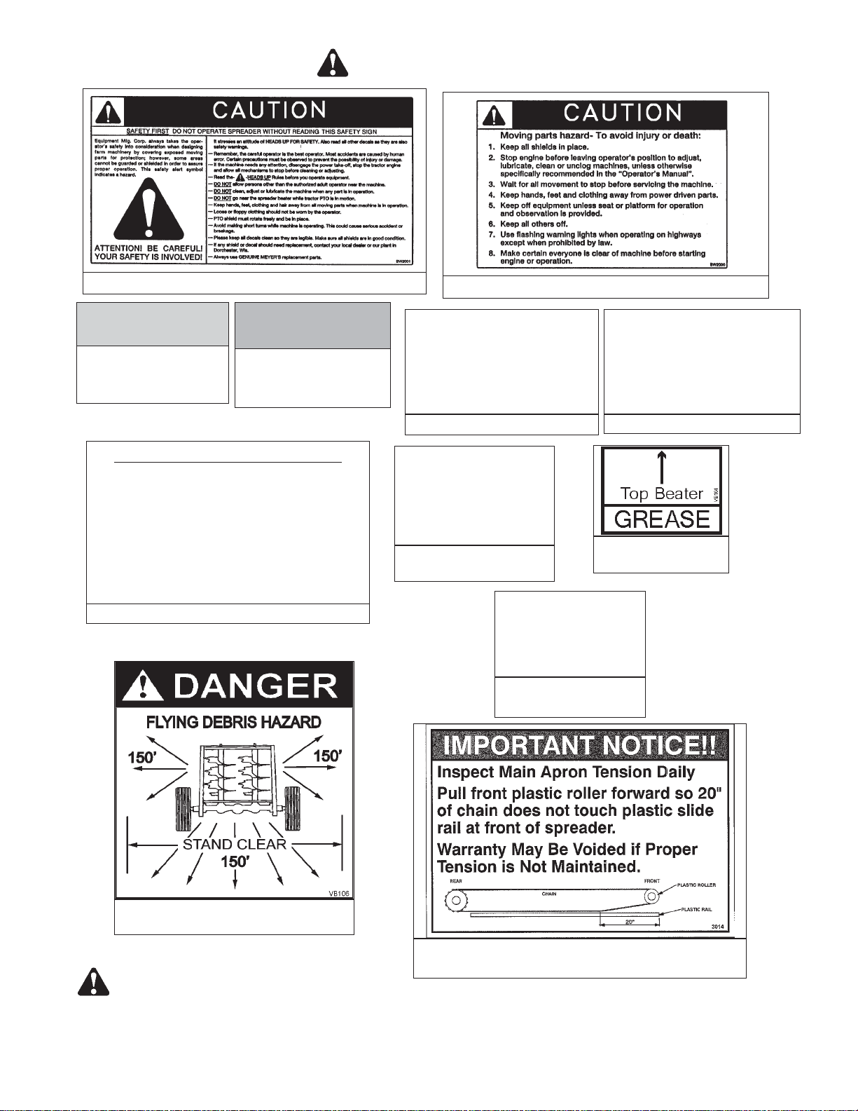
SAFETY SIGNS ....................................... 7
MANURE SPREADER SAFETY ...............................9
MANDATORY SAFETY SHUTDOWN PROCEDURE....................10
PRE-OPERATION...................................... 11
General ......................................... 11
Tractor Hitch And PTO Requirements ..........................11
ADMA Recommendations: ······························11
Tractor Size Requirements................................ 12
Tractor Towing Size Requirements··························12
Material Estimated Weight Per Cubic Foot······················12
Theory Of Operation ................................... 12
Hydraulic System .................................... 12
General········································ 12
Converting A Spreader From Closed Center To Open Center..............13
To Convert Standard Non Flow Controlled Closed Center System To Open
Center······································· 14
To Convert Optional On Board Flow Controlled Closed Center System To
Open Center ···································14
Electric Control Installation for Optional On Board Flow Controlled System .......15
Transporting ....................................... 16
General········································ 16
Use Safety Chain··································· 16
Use Lights ······································ 16
OPERATION ........................................ 17
Tractor Hookup ..................................... 17
Loading ......................................... 17
Unloading ........................................ 17
Mandatory Safety Shutdown Procedure .........................18
MAINTENANCE, ADJUSTMENTS & LUBRICATION ....................19
Wheel And Tire Maintenance And Repair ........................19
Lock Ring Rim ...................................... 19
Rear-Automatic Over Running Clutch ..........................19
Mandatory Safety Shutdown Procedure.........................19
Adjustments ....................................... 20
Apron Chain ····································· 20
Lubrication ........................................ 20
Cleaning And Storage ..................................22
REPAIR PARTS....................................... 24
Main Frame & Box Parts·································24
Hydraulic End Gate & Related Parts···························26
Jack Assembly······································ 28
Axles, Wheels, Spindles And Related Parts ·······················30
Page 3 MODEL: VB750

1 3/4” Drive Train ···································· 32
Apron & Related Parts ··································34
Apron & Related Parts ··································36
Lube Bank ········································ 38
15mm Beater Head Assembly, Standard ························40
Vertical Beaters & Related Parts·····························42
Apron Drive Gearbox··································· 44
RemovableCVTelescoping Universal Joint Assembly WithGuard, Trailer To Tractor · · · · 46
35E Universal Joint, Telescoping Assembly w/ Guard - Rear With Over-Running Clutch ····47
Standard Highway Lighting With Amber Side Light ···················48
Hydraulic Assembly - Electric Flow Control - Closed Center···············50
HydraulicAssembly-NoElectricFlowControl-ClosedCenter···············54
Hydraulic Assembly - No Electric Flow Control - Open Center··············56
Weigh Scale ······································· 58
LIMITED WARRANTY STATEMENT ............................60
MODEL: VB750 Page 4

SAFETY
Page 5 MODEL: VB750
A brief definition of signal words that may be used in
this manual:
DANGER: Indicates an imminently hazardous sit-
uation that, if not avoided, will result in serious injury or
death.
WARNING: Indicates a potentially hazardous sit-
uation that, if not avoided, could result in death or seri-
ous injury, and includes hazards that are exposed when
guards are removed.
CAUTION: Indicates a potentially hazardous situ-
ation that, if not avoided, may result in minor or moder-
ate injury.
CAUTION: IF ANY SAFETY SIGN BECOMES UNREADABLE FOR ANY REASON, THE SIGN MUST BE
REPLACED WITH A NEW SIGN. IF THE SPREADER IS REPAINTED, ALL SAFETY SIGNS MUST BE RE-
PLACED. CONTACT YOUR DEALER OR MEYER’S EQUIPMENT MANUFACTURING CORP. IF YOU RE-
QUIRE ANY SHIELD OR SIGNS FOR REPLACEMENT.
DECALS ARE ILLUSTRATED ON PAGES 7 and 8.
E
G
Also under
shield
V
Located on Driveline
Shields under spreader
H
F
B
B
Typical Illustration
D
ON PTO FRONT
HALF
J
K
C

MODEL: VB750 Page 6
CAUTION: IF ANY SAFETY SIGN BECOMES UNREADABLE FOR ANY REASON, THE SIGN MUST BE
REPLACED WITH A NEW SIGN. IF THE SPREADER IS REPAINTED, ALL SAFETY SIGNS MUST BE RE-
PLACED. CONTACT YOUR DEALER OR MEYER’S EQUIPMENT MANUFACTURING CORP. IF YOU RE-
QUIRE ANY SHIELD OR SIGNS FOR REPLACEMENT.
R
A
U
I
D
L
M
S
M
T
P
I
D
T
L
Q
P
A
M
L
M
DECALS ARE ILLUSTRATED ON PAGES 7 and 8.
S
U
D
D

SAFETY SIGNS
Page 7 MODEL: VB750
DECAL A. PART NO. VB107 DECAL B. PART NO. SW105
DECAL C. PART NO. SW102
DECAL I. PART NO. 3001
DECAL D. PART NO. 700 DECAL E. PART NO. 3003
DECAL G. PART NO. 3006
CAUTION: IF ANY SAFETY SIGN BECOMES UNREADABLE FOR ANY REASON, THE SIGN MUST BE
REPLACED WITH A NEW SIGN. IF THE SPREADER IS REPAINTED, ALL SAFETY SIGNS MUST BE RE-
PLACED. CONTACT YOUR DEALER OR MEYER’S EQUIPMENT MANUFACTURING CORP. IF YOU RE-
QUIRE ANY SHIELD OR SIGNS FOR REPLACEMENT.
DECAL F. PART NO. 3004
DECAL H. PART NO. SW406

MODEL: VB750 Page 8
DECAL J. PART NO. SW2001 DECAL K. PART NO. SW2000
DECAL M. REFLEC-
TIVE TAPE-RED
PART NO. PM17-5915
DECAL L. REFLEC-
TIVE TAPE-YELLOW
PART NO. PM17-5910
CAUTION: IF ANY SAFETY SIGN BECOMES UNREADABLE FOR ANY REASON, THE SIGN MUST BE
REPLACED WITH A NEW SIGN. IF THE SPREADER IS REPAINTED, ALL SAFETY SIGNS MUST BE RE-
PLACED. CONTACT YOUR DEALER OR MEYER’S EQUIPMENT MANUFACTURING CORP. IF YOU RE-
QUIRE ANY SHIELD OR SIGNS FOR REPLACEMENT.
SAFETY SIGNS
START UP PROCEDURE
1. Make certain everyone is clear of machine before starting
engine or operation.
2. Turn Flow Control to Slowest Position.
3. Engage P.T.O.
4. RAISE END GATE.
5. Engage Tractor Hydraulic Lever to Full Flow Position.
6. Start Apron by Rotating Flow Control Dial Clockwise.
DECAL O. PART NO. 3011
DECAL T.
PART NO. VB105
DECAL P. PART NO. VB101 DECAL Q. PART NO. VB102
DECAL R.
PART NO. VB103
DECAL S.
PART NO. VB104
DECAL U.
PART NO. VB106
DECAL V.
PART NO. 3014

Page 9 MODEL: VB750
MANURE SPREADER SAFETY
CAUTION
THERE ARE INHERENT HAZARDS ASSOCIATED WITH THE OPERATION OF A MANURE SPREADER.
FOR YOUR SAFETY:
lNever Enter Spreader Box While In Operation For Any Reason.
lOnly Properly Instructed People Should Operate The Spreader. Do Not Allow Children Or Inexperienced Per-
sons To Operate Spreader.
lKeep All Guards And Shields In Place. Moving Parts Can Crush And Dismember.
lClear The Area Before Equipment Start Up.
lKeep Hands, Feet, And Loose Clothing Away From Moving Parts.
lDo Not Go Near The Spreader Beaters While Machine Is Operating.
lMake Sure The PTO Is Securely Locked To Both The Tractor And Spreader Before Operating The Unit.
lDo Not Operate The PTO At Speeds Higher Than The Manufacturers Recommendations.
lHighway Traffic Is Not To Exceed 20 Mph. The Tires Supplied Are For Farm Use Only And Are Not Designed
For Use Above This Speed Unless Equipped With High Speed Highway/Offroad Farm Tires.
lUse Adequate Safety Chains When Towing The Spreader.
lThe Use Of A Slow moving Vehicle Sign Is Required On All Public Roads Unless Equipped With Flashing
Hazard Lights. Obey All Applicable Highway Safety Laws And Rules.
lAlways Use A Tractor Large Enough To Provide Sufficient Braking Assistance When Towing A Loaded
Spreader.
lUse Caution When Traveling Over Uneven Terrain And When Approaching Stops.
lDo Not Load The Spreader Unless It Is Hitched To The Tractor.
lDo Not Unhitch A Loaded Spreader From The Tractor Leaving It Supported By Only The Jack.
lPark Your Spreader On Level Ground And Place Blocks Ahead Of And Behind The Wheels Before Un-
hooking From Tractor To Avoid Unexpected Rolling When Separated From The Tractor.
lDo Not Allow Riders on Spreader.
FAILURE TO HEED MAY RESULT IN SERIOUS PERSONAL INJURY OR DEATH
CAUTION
THERE ARE ADDITIONAL HAZARDS ASSOCIATED WITH THE SERVICE AND MAINTENANCE OF YOUR
SPREADER.
FOR YOUR SAFETY:
lInspect When First Delivered And Regularly Thereafter; That All Connections And Bolts Are Tight And Secure
Before Operating.
lRetighten All Wheel Bolts After The First Hour Of Towing. Check Periodically Thereafter. See Maintenance, Wheels.
lMaintain Proper Tire Air Pressure At All Times. See Maintenance Chapter, Tires.
lNever Inflate Beyond Rim Or Tire Manufacturer’s Approved Psi Rating. While Inflating, Stay Out Of The Tra-
jectory & Stand Clear Of Tire/Wheel Assembly. A Tire Blow Out Or Rim/Wheel Failure Can Cause Serious In-
jury Or Death.
lIf The Rim Lock Ring Should Blow Off, It And Other Parts Could Fly Off With Enough Force To Injure Or Kill A
Person. Never Stand In The Potential Blow Out Area And Keep Others Away.
lRemoving, Replacing And Repairing Industrial Tires And Rims With Lock Rings Can Be Dangerous Without
Proper Tools, Equipment And Training To Perform This Service. It Is Recommended That This Work Be Per-
formed Only By A Qualified Tire Repair Shop.

MODEL: VB750 Page 10
Most farm accidents, like industrial, home and high-
way accidents, are caused by the failure of some
individuals to observe simple and fundamental
safety rules or precautions. For this reason farm
accidents, just as other types of accidents, can be
prevented by recognizing the causes of accidents
and doing something about them before an acci-
dent occurs.
Regardless of the care used in the design and con-
struction of farm equipment, there are many points
that cannot be completely safe-guarded without in-
terfering with accessibility and efficient operation.
A careful operator is the best insurance against an
accident.
The complete observance of one simple rule would
prevent many thousand serious injuries each year.
That rule is “NEVER ATTEMPT TO CLEAN, OIL,
OR ADJUST A MACHINE WHILE IN MOTION”.
NATIONAL SAFETY COUNCIL
MANDATORY SAFETY SHUTDOWN PROCEDURE
BEFORE unclogging, cleaning, adjusting, lubricating or servicing the unit:
1. Disengage the tractor PTO.
2. Shut off the tractor engine, remove the ignition key and take it with you.
3. Wait for all movement to stop.
4. Remove the Telescoping PTO Drive and ALL power connections from the tractor.
ONLY when you have taken these precautions can you be sure it is safe to proceed. Failure to follow the above
procedure could lead to death or serious bodily injury.
BEFORE ATTEMPTING TO OPERATE YOUR NEW SPREADER BE SURE TO READ THIS OWNERS MANUAL
AND FAMILIARIZE YOURSELF WITH THE MACHINE!! OBSERVE THE PRECAUTIONS IN THIS MANUAL
FOR SAFE OPERATION OF THIS MACHINE!!
lAlways Wear Eye Protection When Operating Or Servicing Spreader.
lBe Sure All Movement Has Stopped, The PTO Is Disconnected, The Tractor Is Shut Off And The Ignition Key
Is Removed Before Servicing The Spreader Or Components.
lEscaping Hydraulic Fluid Under Pressure Can Penetrate The Skin And Cause Serious Injury. Relieve All Pres-
sure From The Hydraulic System Before Connecting Or Disconnecting The Lines Or Making Repairs. Check
All Hoses And Fittings Before Start-up And Periodically During Operation.
lNever Make Any Alterations Or Modifications To This Equipment.
FAILURE TO HEED MAY RESULT IN SERIOUS PERSONAL INJURY OR DEATH

PRE-OPERATION
GENERAL
Read the entire Owners Manual before attempting to
operate this manure spreader. Before attempting any
maintenance or repairs; always be sure all rotating
parts have stopped and that the tractor is shut off, dis-
connect the PTO, relieve all hydraulic pressure and
disconnect hydraulic hoses.
WARNING
NEVER OPERATE SPREADER WITH ANY GUARDS
OR SHIELDS REMOVED. FAILURE TO HEED MAY
RESULT IN SERIOUS PERSONAL INJURY OR
DEATH.
.1 Completely lubricate the unit as described in the
LUBRICATION Section.
.2 Check and tighten the wheel lug nuts if required.
.3 Check and maintain the tire pressure according to
the manufacturer’s recommendation.
.4 Check the entire unit for loose bolts, damaged or
loose hydraulic fittings and hoses or other dam-
aged parts.
.5 The tractor half of the PTO drive shaft assembly
must be locked securely to the tractor output shaft.
TRACTOR HITCH AND PTO
REQUIREMENTS
The spreader is designed to be operated by a 1000
RPM PTO tractor output.
The PTO drive shaft assembly is designed to operate
with tractors conforming to the industry standard
shown on figure 1 for 1000 RPM PTO output.
ADMA Recommendations:
A tractor drawbar equipped with a clevis hitch (ham-
mer-strap) can cause interference with the PTO
driveline IID (implement input driveline). This interfer-
ence can cause serious damage to the IID or the IID
telescoping members. The clevis hitch on the tractor
must be removed.
If the implement (figure 2, top view) is attached to a
tractor with a clevis hitch (hammer-strap) style
drawbar, the hammer-strap must be removed to pre-
vent damage to the IID guarding or the IID telescoping
members.
If the implement (figure 2, lower view) is attached to a
tractor with an offset in the drawbar, be certain it is in
the down position to prevent damage to the IID guard-
ing or the IID telescoping members.
Page 11 MODEL: VB750
FIGURE 1. TRACTOR DRAWBAR & PTO
SPECIFICATION
FIGURE 2. PTO ALIGNMENT
TRACTOR
MASTER SHIELD IMPLEMENT
INPUT
CONNECTION
SHIELD (IIC)
WRONG
WRONG
TRACTOR
MASTER SHIELD ELEMENT INPUT
DRIVELINE (IID)
ELEMENT INPUT
DRIVELINE (IID)

TRACTOR SIZE REQUIREMENTS
The spreader does not have brakes. Towing the
spreader must be done safely. The ASAE (American
Society of Agricultural Engineers) specifies that the
towing vehicle should weigh at least 2/3 as much as
the loaded implement to be reasonably safe towing at
speeds up to 20 mph. This (20 mph) is also the maxi-
mum recommended towing speed for the spreader.
The loaded weight of your spreader will naturally vary
with the moisture of the manure and you must consider
that for your conditions. The loaded weight capacities as
specified by the spreader manufacturer are as follows:
Tractor Towing Size Requirements
Use the following chart for calculating the minimum
tractor weight.
MODEL
(struck
level)
SPREADER EMPTY
WEIGHT + LOAD = GW MINIMUM TRACTOR
WEIGHT UP TO 20
MPH
VB750
(478 ft3)13,340+ _____ = _____ 2/3 of spreader gross
weight
Material Estimated Weight Per Cubic Foot
Material lbs / Cu. Ft.
Lime Sludge 110-115 LBS.
Dry Feedlot Manure 63-65 LBS.
Chicken Litter 63-65 LBS.
Cake Sludge 62-65 LBS.
Semi-Solid Manure 58-60 LBS.
Pen Packed Manure 30-35 LBS.
Liquid Manure 63-65 LBS.
SOURCE: ASAE
NOTICE! Heaped loads have significantly higher capaci-
ties resulting in increased weight and higher center of
gravity, requiring extra precaution during operation.
THEORY OF OPERATION
The spreader rear beaters are driven directly by the
tractor PTO.
The spreader rear end gate and the apron are hydrau-
lic driven. A single set of hydraulic hoses connected to
the tractor hydraulic system is used.
A directional valve is incorporated in the spreader hy-
draulic system which directs hydraulic flow to the rear
end gate only, when the gate is closed. With the gate
closed, applying the tractor hydraulics will open the
gate and as the gate opens, the directional valve is
acted upon by the gate arm and will direct hydraulic
flow to automatically start the apron drive motor.
When unloading is complete, the tractor hydraulic le-
ver is reversed to lower the gate and when the gate is
closed, the directional valve will stop hydraulic flow to
the apron motor. Furthermore, a check valve in the
apron motor circuit will prevent the apron drive motor
from running backwards. The check valve will also
prevent incorrect apron operation if the hydraulic
hoses are accidentally reversed at the tractor.
HYDRAULIC SYSTEM
General
There are two hydraulic systems available for this
spreader. Both systems are shipped for tractor closed
center hydraulics. If using a tractor with open center
hydraulics, instructions to convert the spreader system
to open center are given on page 13. Most late model
tractors are closed center systems. If in doubt, contact
your tractor dealer for information.
The standard spreader hydraulic system does not in-
clude an on board flow control to regulate the apron
speed. Instead, the tractor must have an adjustable
flow control lever (turtle/rabbit icons) and this lever is
used to regulate the spreader apron speed.
If your tractor does not have adjustable flow control,
then your spreader must be equipped with the optional
on board flow control system. This system includes a
motorized flow control to regulate the spreader apron
speed. The motorized valve is adjusted by an electric
control box placed in the tractor cab and connected to
the tractor 12 VDC power source. See figure 5.
MODEL: VB750 Page 12

CONVERTING A SPREADER FROM
CLOSED CENTER TO OPEN CENTER
WARNING
ESCAPING HYDRAULIC FLUID UNDER PRESSURE
CAN PENETRATE THE SKIN AND CAUSE SERIOUS
INJURY. RELIEVE ALL PRESSURE FROM THE
HYDRAULIC SYSTEM BEFORE CONNECTING OR
DISCONNECTING THE LINES OR MAKING
REPAIRS. CHECK ALL HOSES AND FITTINGS
BEFORE START-UP AND PERIODICALLY DURING
OPERATION.
Most late model tractors use a closed center hydraulic
system which only pumps oil as required. Some other
tractors may have an open center system which
pumps oil continuously, in which case provision must
be made to allow excess flow back to the tractor reser-
voir. This is done by converting your spreader to open
center as instructed in the following.
If you are not sure of your system, contact your tractor
dealer.
Page 13 MODEL: VB750
FIGURE 3. TO CONVERT ON NON FLOW CONTROLLED CLOSED CENTER SYSTEM TO OPEN CENTER

NOTICE! For tractors with closed center system and
load sensing that has a priority flow circuit that is man-
ually adjustable, your spreader must have the optional
on board flow control and it must be converted to an
open center system. This is not a tractor lever oper-
ated system.
To Convert Standard Non Flow Controlled Closed
Center System To Open Center
See figure 3 for instructions in suggested numbered
sequence.
A new elbow fitting is required, see page 52 for part
numbers.
To Convert Optional On Board Flow Controlled
Closed Center System To Open Center
See figure 4 for instructions in suggested numbered
sequence.
A new elbow fitting and 12” are required, see page 54
for part numbers.
MODEL: VB750 Page 14
FIGURE 4. TO CONVERT ON BOARD FLOW CONTROLLED CLOSED CENTER SYSTEM TO OPEN CENTER

ELECTRIC CONTROL INSTALLATION FOR
OPTIONAL ON BOARD FLOW CON-
TROLLED SYSTEM
.1 Locate the controller on the tractor where it is ac-
cessible to operate.
.2 Connect the electrical leads to the tractor 12VDC
power source, figure 5.
.3 When hooking up the spreader, connect the con-
troller to the motorized flow control valve at the
twist lok connector.
Page 15 MODEL: VB750
FIGURE 5. ELECTRIC MOTORIZED FLOW CONTROL
MOTORIZED FLOW
CONTROL VALVE
APRON RATE
SPEED
“ON/OFF” SWITCH
TWIST LOK CONNECTOR
CONNECT RED (+) AND BLACK (-) WIRES
TO 12 VDC TRACTOR POWER SOURCE

TRANSPORTING
General
Check for traffic constantly. Be sure you can see that
no one is attempting to pass you and that all traffic is
sufficiently clear from you before making any turns.
WARNING
BE SURE THE SLOW MOVING VEHICLE SIGN IS
INSTALLED ON THE REAR OF THE SPREADER
FOR TRANSPORTING ON ROADWAYS. KEEP THIS
SIGN AND ALL REFLECTIVE DECALS CLEAN. FAIL-
URE TO HEED MAY RESULT IN SERIOUS PER-
SONAL INJURY OR DEATH.
CAUTION:
REGULARLY CLEAN OFF THE REFLECTIVE TAPE
AT THE REAR AND SIDES OF THE SPREADER
WHEN TRANSPORTING IT ON THE HIGHWAY.
WARNING
DO NOT TOW AT SPEEDS GREATER THAN 20
MPH. FAILURE TO HEED MAY RESULT IN SERI-
OUS PERSONAL INJURY OR DEATH.
Operating speed is dictated by the terrain over which
you are traveling. Always use caution. Avoid traveling
on slopes or hills that are unsafe. Also beware of slip-
pery conditions such as traveling over areas previously
spread with manure. If possible, avoid spreading over
areas where manure has been previously applied.
If you will travel on public roadways and it is le-
gal to do so, you must know all rules governing
such operation. This will include lighting and
brake requirements in addition to traffic rules.
You may also be required to install a safety
chain on the spreader.
Use Safety Chain
CAUTION:
A SAFETY CHAIN SHOULD BE INSTALLED
TO RETAIN THE CONNECTION BETWEEN
TRACTOR (OR OTHER TOWING VEHICLE)
AND SPREADER WHENEVER TRAVELING
ON PUBLIC ROADS. A SUGGESTED AT-
TACHMENT IS ILLUSTRATED ON FIGURE 6.
The chain must be strong enough to hold the weight of
the loaded spreader. If using a grab hook at the end(s)
of the chain to secure the chain to itself, a hook latch
must be installed.
The length of the safety chain is not to be any longer
than necessary to turn without interference. If any
chain links or attachment hardware are broken or
stretched, repair before using. Store chain so it does
not corrode or become damaged. Do not use this
chain for other implements because the strength and
length of chain may not be adequate. Identify this
chain for use on this particular spreader.
Safety chain designed for this spreader can be or-
dered on page 24.
Use Lights
Optional lights (see page 48) are offered for your
spreader. Lights are recommended for any spreader
operated on public roads and may be a requirement.
If equipped with lights, plug the electric plug into the
tractor trailer electrical receptacle.
MODEL: VB750 Page 16
FIGURE 6. SUGGESTED SAFETY CHAIN INSTALLATION
GRAB HOOK W/LATCH
INTERMEDIATE SUPPORT

Page 17 MODEL: VB750
OPERATION
DANGER
NEVER ENTER THE SPREADER BOX FOR ANY
REASON WITHOUT FIRST DISCONNECTING PTO
SHAFT FROM TRACTOR. DO NOT ALLOW
OTHERS IN THE BOX. ROTATING BEATER CAN
DISMEMBER OR KILL.
TRACTOR HOOKUP
CAUTION
DO NOT USE JACK EXCEPT WHEN SPREADER IS
EMPTY. JACK WILL NOT SUPPORT ADDED
WEIGHT FROM LOAD. UNBALANCED WEIGHT
MAY RESULT IN UNEXPECTED “TIP UP” OF THE
SPREADER.
1. Hook the spreader hitch to the tractor drawbar
with 1 3/8” secured hitch pin.
2. Raise the jack off the ground. Remove the jack
hub pin and rotate the jack to horizontal storage
position and secure with the pin, figure 7.
3. Connect the PTO drive shaft to the tractor PTO
output shaft and be sure it is locked to the tractor
shaft.
4. Connect the two hydraulic hoses from the
spreader a set of remote ports on the tractor.
NOTICE! The return line on the spreader apron motor
has a check valve in it so that the apron can not be
operated in the wrong direction. If the hoses are re-
versed, the apron will not operate and the hoses
should be switched.
5. If you have an optional on board flow control with
electric control system, plug the twist lok connec-
tors together. See figure 5 for mounting instruc-
tions.
LOADING
1. Check that the end gate is closed, figure 8. When
the spreader is parked for loading, shift the tractor
to neutral or park and set the brakes. The moisture
content of the manure will determine how full the
spreader can be loaded so that no manure spills
out.
2. You will probably be able to load solid manure at
least level with the top of the box while semi liquid
and liquid slurries will have to be less than full in
the spreader box.
NOTICE! It is unlawful to allow slurry to splash or leak
onto public roads.
UNLOADING
DANGER
KEEP AWAY AND KEEP OTHERS CLEAR OF RO-
TATING BEATERS AT REAR OF SPREADER. SERI-
OUS INJURY OR AMPUTATION COULD RESULT.
WARNING
FIGURE 7. SPREADER HOOK UP
FIGURE 8. HYDRAULIC END GATE,
VIEW FROM REAR
END GATE

MAKE CERTAIN EVERYONE IS CLEAR OF EQUIP-
MENT BEFORE APPLYING POWER. FAILURE TO
HEED MAY RESULT IN SERIOUS PERSONAL IN-
JURY OR DEATH.
The rear beaters have been designed and tested to
provide the best spread pattern for most liquids and
semi solid manure. However, the pattern will vary for
each specific condition. The factors that contribute
most to differing patterns will be moisture content and
the amount and length of bedding material. For most
typical conditions, the spread pattern should be uni-
form and about 30 feet wide or more for cattle manure
and about 20 feet wide for poultry manure. Plan your
spreading patterns so you do not have to travel over
previously spread manure which will be slippery, re-
sulting in poor traction. Traction on wet grass is also
poor. When the resulting pattern may require that you
overlap during spreading, use precautions on slopes
and hills where you will experience a loss of traction by
traveling over ground with previously spread manure.
CAUTION
DO NOT OPERATE APRON CHAIN WITHOUT
RAISING END GATE FIRST. FAILURE TO HEED
MAY RESULT IN EQUIPMENT DAMAGE.
1. When you are ready to begin spreading applica-
tion on the field, slowly engage the tractor PTO
clutch and then increase PTO to operating speed.
2. Open the hydraulic end gate, figure 8, by applying
the tractor hydraulic lever. This can be done while
traveling forward to avoid a heavier application at
the edge of the field than desired.
3. When the end gate begins to open, the apron
drive will start automatically.
4. For standard non flow control systems, regulate
the apron speed with the tractor hydraulic system
adjustable flow control lever (rabbit/turtle icons).
5. For optional on board flow control with electric con-
trol box, turn the electric control to “ON”. Turn the
knob CW to increase or CCW to decrease applica-
tion rate. Return switch to “OFF” when spreading is
completed, figure 5.
6. For solid manure, start the apron at a slow rate of
speed.
7. Start application onto the field. Increase the speed
of apron chain for a heavier application.
NOTICE! Do not feed frozen manure at a rate too fast.
The apron drive can feed faster than the beaters can
expel the material. When frozen chunks are present,
reduce apron speed to approximately 1/3, to allow the
beaters time to grind the chunks into small pieces.
8. Further control of the application rate is possible
by the relationship of tractor engine speed to
ground speed (transmission gear selection). For
optimum trouble free performance it is recom-
mended to operate at or near engine PTO speed.
9. When the spreader is empty, stop the PTO.
10. Reverse the tractor hydraulic lever. This will close
the gate and stop the apron.
MANDATORY SAFETY SHUTDOWN
PROCEDURE
BEFORE unclogging, cleaning, adjusting, lubricating
or servicing the unit:
1. Disengage the tractor PTO.
2. Shut off the tractor engine, remove the ignition key
and take it with you.
3. Wait for all movement to stop.
4. Remove the Telescoping PTO Drive and ALL
power connections from the tractor.
ONLY when you have taken these precautions can
you be sure it is safe to proceed. Failure to follow the
above procedure could lead to death or serious bodily
injury.
MODEL: VB750 Page 18

MAINTENANCE, ADJUSTMENTS & LUBRICATION
WARNING
DISCONNECT PTO DRIVE SHAFT AND HYDRAULIC
HOSES BEFORE CLEANING, ADJUSTING OR SER-
VICING THIS MACHINE. FAILURE TO HEED MAY RE-
SULT IN SERIOUS PERSONAL INJURY OR DEATH.
WARNING
APRON STARTS AUTOMATICALLY WHEN GATE
OPENS.
WHEEL AND TIRE MAINTENANCE AND
REPAIR
WHEELS: Check periodically. The wheel studs should
be torqued to 297 foot pounds.
VB750 TIRE PRESSURE:
75 psi, recommended pressure, 77 psi max.
LOCK RING RIM
WARNING
NEVER INFLATE BEYOND RIM OR TIRE MANU-
FACTURER’S APPROVED PSI RATING. WHILE IN-
FLATING, STAY OUT OF THE TRAJECTORY &
STAND CLEAR OF TIRE/WHEEL ASSEMBLY. A
TIRE BLOW OUT OR RIM/WHEEL FAILURE CAN
CAUSE SERIOUS INJURY OR DEATH.
Removing, replacing and repairing industrial tires and
rims with lock rings can be dangerous without proper
tools, equipment and training to perform this service. It
is recommended that this work be performed only by a
qualified tire repair shop.
DANGER
IF THE LOCK RING SHOULD BLOW OFF, IT AND
OTHER PARTS COULD FLY OFF WITH ENOUGH
FORCE TO INJURE OR KILL A PERSON. NEVER
STAND IN THE POTENTIAL BLOW OUT AREA AND
KEEP OTHERS AWAY.
REAR-AUTOMATIC OVER RUNNING
CLUTCH
(See figure 9)
1. If the PTO drive becomes over loaded, the clutch
will disengage, causing an audible clattering noise.
2. If the clutch disengages, stop tractor hydraulic
flow. Disengage the PTO and allow it to coast
down. The clutch will re-engage at slow speed if
the over load has subsided.
3. At slow speed, re-engage the PTO and allow the
beaters to run freely. Restart the hydraulic flow
and resume operation.
4. If the clutch will not re-engage, then the beaters
are still over loaded or plugged. It will be neces-
sary to manually unplug the beaters to remove the
clog. A foreign object such as a rock may be found
to be the cause of over load.
5. When the clog has been cleared, restart the trac-
tor and at idle speed, engage the PTO until the
beaters fun freely. Increase the PTO speed and
then engage the hydraulic flow to operate the
apron drive and resume operation.
MANDATORY SAFETY SHUTDOWN
PROCEDURE
BEFORE unclogging, cleaning, adjusting, lubricating
or servicing the unit:
1. Disengage the tractor PTO.
2. Shut off the tractor engine, remove the ignition key
and take it with you.
3. Wait for all movement to stop.
4. Remove the Telescoping PTO Drive and ALL
power connections from the tractor.
ONLY when you have taken these precautions can
you be sure it is safe to proceed. Failure to follow the
above procedure could lead to death or serious bodily
injury.
Page 19 MODEL: VB750
FIGURE 9. AUTOMATIC OVER RUNNING CLUTCH

ADJUSTMENTS
Apron Chain
The apron chain is adjusted by (4) adjuster bolts
located on the front of the box frame, figure 13. Adjust
the 1-1/8” bolts so the chain is elevated above the
plastic slide rails for 36” as illustrated on figure 10.
When there is no more adjustment left on the adjuster
screws, loosen the nuts on the bolts and push the
bolts in as far as they will go. Then remove a link from
each chain and readjust the apron chain
NOTICE! Chain must run centered on the front nylon
rollers.
LUBRICATION
Grease bearings on top of Vertical Beater one pump
every 8 hours, both sides by grease lines. Figures 11 and
12.
Maintain oil level in apron drive reducer at check
level plug, accessible at right, rear side. It holds 6 Qts.
When required, refill with SAE 85-140 Moly Fortified
gear lube or Synthetic SAE 75-90 gear lube. Figure 11.
Grease 3 bearings on the drive shaft under spreader
box, one pump every 8 hours. These bearings are ac-
cessed by grease lines, 3 places on RH side of machine.
Figures 11 and 14.
There are two bearings at the front of the driveline
connecting to the PTO shaft. Grease these bearings
one pump every 8 hours. Figure 13.
Grease Pivot Hitch 2 pumps every 8 hours, each
grease zerk. Figure 13.
MODEL: VB750 Page 20
FIGURE 10. ADJUST APRON CHAIN FIGURE 11.
L1
L6
L7
L2
SIGHT GLASS
REMOVE
SHIELD
L3
L2
FIGURE 12.
L6
L1
L7
L8
SIGHT GLASS
L12
L13
FIGURE 13.
UNDERNEATH
L4
A1
A1
A1
L5
A1
L1
L2
L3
L4
L5
Other manuals for VB750
1
Table of contents
Other Meyer's Spreader manuals

Meyer's
Meyer's 3465 User manual

Meyer's
Meyer's VB900 User manual

Meyer's
Meyer's VB375 User manual

Meyer's
Meyer's 3465 User manual

Meyer's
Meyer's 435 Tandem User manual

Meyer's
Meyer's MS485 User manual

Meyer's
Meyer's VB185 User manual

Meyer's
Meyer's 3280 User manual

Meyer's
Meyer's VB560 User manual

Meyer's
Meyer's VB440 User manual