Meyer's 435 Tandem User manual

INSTRUCTION AND PARTS BOOK NO. 10-1
HEAVY DUTY MANURE SPREADERS
MODEL 435 Tandem
DO NOT
operate this Spreader until you have
read this book
NEVER
repair or clean this Spreader while
PTO is engaged
Manufactured in DORCHESTER, WISCONSIN by
MEYER’S
EQUIPMENT
MFG. CORP.
01/10

Page 2 Model 435
INTRODUCTION
Congratulations on the purchase of your new Meyer’s
Manure Spreader. With its optional equipment this is
the simplest, most flexible system on the market
today. With proper operation and preventative
maintenance it will last for years.
This SAFETY ALERT SYMBOL means
ATTENTION! BE CAREFUL! YOUR SAFETY IS
INVOLVED! It stresses an attitude of HEADS UP
FOR SAFETY. When you see this symbol, be alert to
the possibility of PERSONAL INJURY and carefully
read the message that follows.
WARNING:
Never operate without all covers, shields and guards
in place. Keep hands, feet and clothing away from
moving parts. Some covers and guards have been
removed for illustrative purposes only in this manual.
Failure to heed may result in serious personal injury
or death.
At the front of this manual is a Product Registration
and Inspection Certificate. Be sure your dealer has
completed this certificate and forwarded a copy to the
manufacturer to validate the manufacturer’s warranty.
The product model and serial number are recorded
on this certificate for your convenience and for proper
identification of your spreader by your dealer and the
manufacturer when ordering repair parts.
The serial number plate is found on the front hitch
weldment, below the rear end of the PTO drive shaft.
For information on ordering repair parts, refer to the
repair parts section of this manual. Orders must list
the complete description, correct part number, and
total amount required.
All references to right hand and left hand apply to the
product as viewed from the rear of the machine.
You are urged to study this manual and follow the
instructions carefully. Your efforts will be repaid in
better operation and service as well as a savings in
time and repair expense. Failure to read this manual
and understand the machine could lead to serious
injury. If you do not understand instructions in this
manual, contact either your dealer or Meyer’s
Equipment Manufacturing Corp. at Dorchester, WI
54425.
This supersedes all previous published instructions

Model 435 Page 3
TABLE OF CONTENTS
INTRODUCTION ..........................................................................................................................................................2
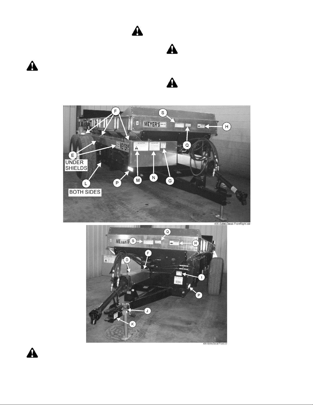
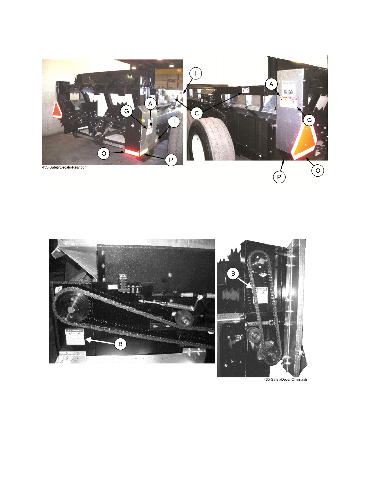
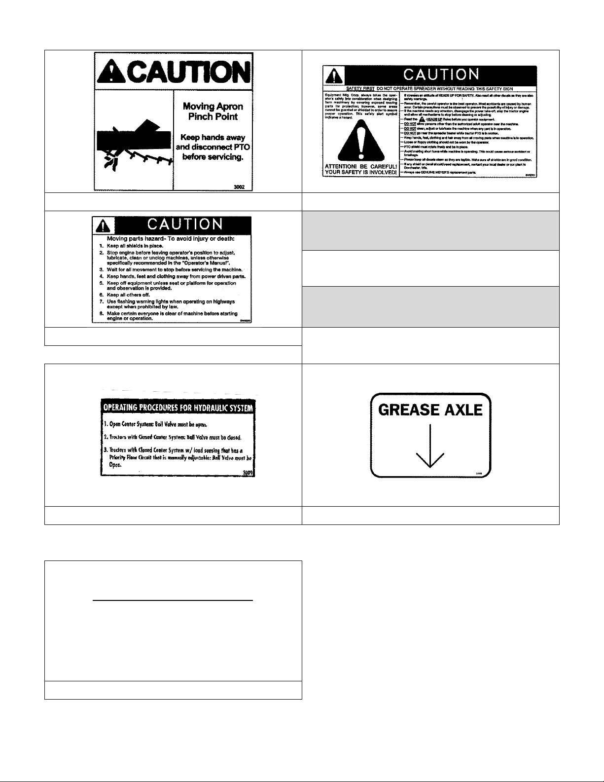
SAFETY ........................................................................................................................................................................4
MANURE SPREADER SAFETY...................................................................................................................................8
MANDATORY SAFETY SHUTDOWN PROCEDURE .................................................................................................9
PRE-OPERATION ......................................................................................................................................................10
General....................................................................................................................................................................10
Tractor Hookup........................................................................................................................................................10
Tractor Requirements..........................................................................................................................................10
Tractor Size .........................................................................................................................................................10
Tractor Towing Size Requirements .....................................................................................................................10
Material Estimated Weight Per Cubic Foot .........................................................................................................10
Tractor Hookup....................................................................................................................................................11
Hydraulic Apron Drive .............................................................................................................................................11
Hydraulic System ....................................................................................................................................................11
Transporting ............................................................................................................................................................12
Use Safety Chain.................................................................................................................................................12
OPERATION...............................................................................................................................................................13
DANGER.....................................................................................................................................................................13
Loading....................................................................................................................................................................13
Unloading ................................................................................................................................................................13
Hydraulic Apron Drive Operation ............................................................................................................................13
Hydraulic End Gate Operation ................................................................................................................................14
Unhook Spreader From Tractor ..............................................................................................................................14
MANDATORY SAFETY SHUTDOWN PROCEDURE ...............................................................................................14
MAINTENANCE, LUBRICATION & ADJUSTMENTS ................................................................................................15
Cleaning And Storage .............................................................................................................................................15
Lubrication ...............................................................................................................................................................15
Shear Pin Hub Maintenance ...................................................................................................................................16
Adjustments.............................................................................................................................................................17
Apron Chain.........................................................................................................................................................17
Roller Chain Adjustment......................................................................................................................................17
REPAIR PARTS..........................................................................................................................................................20
Main Frame and Box Parts......................................................................................................................................20
Axles, Wheels, Spindles and Related Parts............................................................................................................22
Jack .........................................................................................................................................................................24
Hydraulic End Gate .................................................................................................................................................26
End Gate Hydraulics ...............................................................................................................................................28
Front and Side Drive Shaft and Related Parts........................................................................................................30
Apron Parts .............................................................................................................................................................32
Apron and Lower Beater Drive................................................................................................................................34
Apron Drive Gear box..............................................................................................................................................36
5490-0672 Gear Box Complete 540 RPM Beater Drive Gearbox ..........................................................................38
5490-0685 Gear Box Complete 1000 RPM Beater Drive Gearbox ........................................................................40
E01300W Gear box Complete 540 RPM Beater Drive Gearbox ............................................................................42
4190-0532 Gear Box Complete 1,000 RPM Beater Drive Gearbox .......................................................................44
Beaters and Related Parts ......................................................................................................................................46
Apron Drive Hydraulics............................................................................................................................................48
PTO Shaft Assembly ...............................................................................................................................................50
LIMITED WARRANTY STATEMENT .........................................................................................................................52

Page 4 Model 435
SAFETY
A brief definition of signal words that may be used in
this manual:
DANGER: Indicates an imminently hazardous
situation that, if not avoided, will result in serious
injury or death.
WARNING: Indicates a potentially hazardous
situation that, if not avoided, could result in death or
serious injury, and includes hazards that are exposed
when guards are removed.
CAUTION: Indicates a potentially hazardous
situation that, if not avoided, may result in minor or
moderate injury.
CAUTION: If any safety decal becomes unreadable for any reason, the decal must be replaced with a new
decal. If the spreader is repainted, all safety decals must be replaced. Contact your dealer or Meyer’s Equipment
Manufacturing Corp. if you require any shield or decals for replacement.

Model 435 Page 5

Page 6 Model 435
DECAL A. PART NO. 3000 DECAL B. PART NO. SW404-1 DECAL C. PART NO. 3001
DECAL D. PART NO. SW104 DECAL E. PART NO. SW102 DECAL F. PART NO. SW406
DECAL G. PART NO. SW404 DECAL H. PART NO. 3006
DECAL I. PART NO. 700 DECAL J. PART NO. 3003 DECAL K. PART NO. 3004

Model 435 Page 7
DECAL L. PART NO. 3002 DECAL M. PART NO. SW2001
DECAL O. REFECTIVE TAPE RED
PART NO. PM17-5915
DECAL N. PART NO. SW2000 DECAL O. REFECTIVE TAPE YELLOW
PART NO. PM17-5910
DECAL Q. PART NO. 3009 DECAL R. PART NO. 3008
START UP PROCEDURE
1. Make certain everyone is clear of machine before starting engine or
operation.
2. Turn Flow Control to Slowest Position.
3. Engage P.T.O.
4. RAISE END GATE.
5. Engage Tractor Hydraulic Lever to Full Flow Position.
6. Start Apron by Rotating Flow Control Dial Clockwise.
DECAL S. PART NO. 3011

Page 8 Model 435
MANURE SPREADER SAFETY
CAUTION
THERE ARE INHERENT HAZARDS ASSOCIATED WITH THE OPERATION OF A MANURE SPREADER.
FOR YOUR SAFETY:
•Never Enter Spreader Box While In Operation For Any Reason.
•Only Properly Instructed People Should Operate The Spreader. Do Not Allow Children Or Inexperienced
Persons To Operate Spreader.
•Keep All Guards And Shields In Place. Moving Parts Can Crush And Dismember.
•Clear The Area Before Equipment Start Up.
•Keep Hands, Feet, And Loose Clothing Away From Moving Parts.
•Do Not Go Near The Spreader Beaters While Machine Is Operating.
•It Is Not Safe To Clean Or Service The Spreader With Power Operating. PTO Drive And Hydraulics Must Be
Disconnected.
•Make Sure The PTO Is Securely Locked To Both The Tractor And Spreader Before Operating The Unit.
•Do Not Operate The PTO At Speeds Higher Than The Manufacturers Recommendations.
•Highway Traffic Is Not To Exceed 20 Mph. The Tires Supplied Are For Farm Use Only And Are Not Designed
For Use Above This Speed.
•Use Adequate Safety Chains When Towing The Spreader.
•The Use Of A Slow Moving Vehicle Sign Is Required On All Public Roads. Obey All Applicable Highway
Safety Laws And Rules.
•Always Use A Tractor Large Enough To Provide Sufficient Braking Assistance When Towing A Loaded
Spreader.
•Use Caution When Traveling Over Uneven Terrain And When Approaching Stops.
•Do Not Load The Spreader Unless It Is Hitched To The Tractor.
•Do Not Unhitch A Loaded Spreader From The Tractor Leaving It Supported By Only The Jack.
•Park Your Spreader On Level Ground And Place Blocks Ahead Of And Behind The Wheels Before
Unhooking From Tractor To Avoid Unexpected Rolling When Separated From The Tractor.
CAUTION
THERE ARE ADDITIONAL HAZARDS ASSOCIATED WITH THE SERVICE AND MAINTENANCE OF YOUR
SPREADER.
FOR YOUR SAFETY:
•Inspect When First Delivered And Regularly Thereafter; That All Connections And Bolts Are Tight And
Secure Before Operating.
•Retighten All Wheel Bolts After The First Hour Of Towing. Check Periodically Thereafter. See Maintenance,
Wheels.
•Maintain Proper Tire Air Pressure At All Times. See Maintenance, Tire Pressure.
•Always Wear Eye Protection When Operating Or Servicing Spreader.
•Be Sure All Movement Has Stopped, The PTO Is Disconnected, The Tractor Is Shut Off And The Ignition Key
Is Removed Before Servicing The Spreader Or Components.
•Escaping Hydraulic Fluid Under Pressure Can Penetrate The Skin And Cause Serious Injury. Relieve All
Pressure From The Hydraulic System Before Connecting Or Disconnecting The Lines Or Making Repairs.
Check All Hoses And Fittings Before Start-up And Periodically During Operation.
•Never Make Any Alterations Or Modifications To This Equipment.
FAILURE TO HEED MAY RESULT IN SERIOUS PERSONAL INJURY OR
DEATH

Model 435 Page 9
MANDATORY SAFETY SHUTDOWN PROCEDURE
BEFORE unclogging, cleaning, adjusting, lubricating or servicing the unit:
1. Disengage the tractor PTO.
2. Shut off the tractor engine, remove the ignition key and take it with you.
3. Wait for all movement to stop.
4. Remove the Telescoping PTO Drive and ALL power connections from the tractor.
ONLY when you have taken these precautions can you be sure it is safe to proceed. Failure to follow the above
procedure could lead to death or serious bodily injury.
Most farm accidents, like industrial, home and highway accidents, are caused by the failure of some individuals to
observe simple and fundamental safety rules or precautions. For this reason, farm accidents, just as other types of
accidents, can be prevented by recognizing the causes of accidents and doing something about them before an
accident occurs.
Regardless of the care used in the design and construction of farm equipment, there are many points that cannot
be completely safe-guarded without interfering with accessibility and efficient operation.
A careful operator is the best insurance against an accident.
The complete observance of one simple rule would prevent many thousand serious injuries each year. That rule is
“NEVER ATTEMPT TO CLEAN, OIL, OR ADJUST A MACHINE WHILE IN MOTION”.
NATIONAL SAFETY COUNCIL
BEFORE ATTEMPTING TO OPERATE YOUR NEW SPREADER BE SURE TO READ THIS OWNER’S MANUAL
AND FAMILIARIZE YOURSELF WITH THE MACHINE!! OBSERVE THE PRECAUTIONS IN THIS MANUAL FOR
SAFE OPERATION OF THIS MACHINE!!

Page 10 Model 435
PRE-OPERATION
GENERAL
Read the entire Owner’s Manual before attempting to
operate this manure spreader. Before attempting any
maintenance or repairs; always be sure all rotating
parts have stopped and that the tractor is shut off,
disconnect the PTO, relieve all hydraulic pressure
and disconnect hydraulic hoses.
WARNING
Never operate spreader with any guards or shields
removed. Failure to heed may result in serious
personal injury or death.
1. Completely lubricate the unit as described in the
Maintenance Section of this manual.
2. Check and tighten the wheel lug nuts if required.
3. Check and maintain the tire pressure according
to the Maintenance Section of this manual.
4. Check the entire unit for loose bolts, damaged or
loose hydraulic fittings and hoses or other
damaged parts.
5. The tractor half of the PTO drive shaft assembly
must be locked securely to the tractor output
shaft.
TRACTOR HOOKUP
Tractor Requirements
1. The spreader is designed to be operated by a
540 rpm PTO tractor output. In addition, 1 set of
tractor remote hydraulic ports are required, to
operate the apron drive and a second set of ports
will be required for the hydraulic end gate.
FIGURE
1
. TRACTOR DRAWBAR &
PTO
SPECIFICATION
2. The PTO drive shaft assembly is designed to
operate with tractors conforming to the industry
standard shown on Figure 1 for 540 RPM PTO
output.
Tractor Size
1. The spreader does not have brakes. Towing the
spreader must be done safely. The ASAE
(American Society of Agricultural Engineers)
specifies that the towing vehicle should weigh at
least 2/3 as much as the loaded implement to be
reasonably safe towing at speeds up to 20 mph.
This (20 mph) is also the maximum
recommended towing speed for the spreader.
2. The loaded weight of your spreader will naturally
vary with the moisture of the manure and you
must consider that for your conditions. The
loaded weight capacities as specified by the
spreader manufacturer are as follows:
Tractor Towing Size Requirements
Use the following chart for calculating the minimum
tractor weight.
MODEL
(struck
level)
SPREADER EMPTY
WEIGHT + LOAD =
GROSS WEIGHT
MINIMUM
TRACTOR
WEIGHT UP TO
20 MPH
435
(540 cu ft)
6600 + _____ = _____ 2/3 of spreader
gross weight
Material Estimated Weight Per Cubic Foot
Material
lbs/Cu. Ft.
Lime Sludge 110-115 lbs.
Dry Feedlot Manure 63-65 lbs.
Chicken Litter 63-65 lbs.
Cake Sludge 62-65 lbs.
Semi-Solid Manure 58-60 lbs.
Pen Packed Manure 30-35 lbs.
Liquid Manure 63-65 lbs.
SOURCE: ASAE

Model 435 Page 11
NOTE: Heaped loads have significantly higher
capacities resulting in increased weight and higher
center of gravity, requiring extra precaution during
operation.
Tractor Hookup
FIGURE
2
. TRACTOR HOOKUP
1. Hook the spreader hitch to the tractor drawbar
with secured hitch pin conforming to the pin hole
size in the spreader hitch.
2. Raise the jack off the ground. Remove the jack
hub pin and rotate the jack to horizontal storage
position and secure with the pin.
3. Connect the PTO drive shaft to the tractor PTO
output shaft and be sure it is locked to the tractor
shaft.
HYDRAULIC APRON DRIVE
1. Connect the two hydraulic hoses for the apron
drive to a set of remote ports on the tractor.
These are the two hoses coming from the
hydraulic flow control valve.
NOTE: One of the lines going to the flow control has
a check valve in it so that the apron cannot be
operated in the wrong direction. This line must be
connected to the tractor return port. If the hoses are
reversed, the apron will not operate and the hoses
should be switched.
2. A “control hose” is connected to the flow control
lever with the opposite end having a bracket to
hook at a convenient location on the tractor for
operator convenience. The flow control lever has
a tension screw adjustment to regulate force to
retain settings, Figure 3.
3. Connect the two hydraulic hoses for the end gate
to a second pair of tractor remote ports.
HYDRAULIC SYSTEM
1. Most late model tractors use a Closed Center
hydraulic system which only pumps oil as
required. Some other tractors may have an Open
Center system which pumps oil continuously, in
which case provision must be made to allow
excess flow through the return hose back to the
tractor reservoir by closing the ball valve on the
flow control. If you are not sure of your system,
contact your tractor dealer.
2. The spreader is normally shipped with the apron
drive flow control valve plumbed for Open
Centers as illustrated on Figure 3. If you have a
Closed Center, close the ball valve shown on
Figure 3.
FIGURE
3
. FLOW CONTROL

Page 12 Model 435
TRANSPORTING
1. Check for traffic constantly. Be sure you can see
that no one is attempting to pass you and that all
traffic is sufficiently clear from you before making
any turns.
WARNING
Be sure the slow moving vehicle sign is installed on
the rear of the spreader for transporting on roadways.
Keep this sign and all reflective decals clean. Failure
to heed may result in serious personal injury or
death.
WARNING
Do not tow at speeds greater than 20 mph. Failure to
heed may result in serious personal injury or death.
CAUTION
Regularly clean off the reflective tape at the rear and
sides of the spreader when transporting it on the
highway.
2. Operating speed is dictated by the terrain over
which you are traveling. Always use caution.
Avoid traveling on slopes or hills that are unsafe.
Also beware of slippery conditions such as
traveling over areas previously spread with
manure. If possible, avoid spreading over areas
where manure has been previously applied.
3. If you will travel on public roadways and it is legal
to do so, you must know all rules governing such
operation. This will include lighting and brake
requirements in addition to traffic rules. You may
also be required to install a safety chain on the
spreader.
Use Safety Chain
CAUTION
A safety chain should be installed to retain the
connection between tractor (or other towing vehicle)
and spreader whenever traveling on public roads. A
suggested attachment is illustrated on Figure 4.
1. The chain must be strong enough to hold the
weight of the loaded spreader. If using a grab
hook at the end(s) of the chain to secure the
chain to itself, a hook latch must be installed.
2. The length of the safety chain is not to be any
longer than necessary to turn without
interference. If any chain links or attachment
hardware are broken or stretched, repair before
using. Store chain so it does not corrode or
become damaged. Do not use this chain for other
implements because the strength and length of
chain may not be adequate. Identify this chain for
use on this particular spreader.
Safety chain designed for this spreader can be
ordered on page 20.
FIGURE
4
. SUGGESTED SAFETY C
HAIN
INSTALLATION

Model 435 Page 13
OPERATION
DANGER
Never enter the spreader box for any reason without
first disconnecting PTO shaft from tractor. Do not allow
others in the box. Rotating beater can dismember or
kill.
CAUTION
Do not use jack except when spreader is empty. Jack
will not support added weight from load. Unbalanced
weight may result in unexpected “tip up” of the
spreader.
LOADING
1. Be sure the hydraulic end gate is closed, Figure 5.
When the spreader is parked for loading, shift the
tractor to neutral or park and set the brakes. The
moisture content of the manure will determine how
full the spreader can be loaded so that no manure
spills out.
2. You will probably be able to load solid manure at
least level with the top of the box while semi liquid
and liquid slurries will have to be less than full in
the spreader box.
NOTE: It is unlawful to allow slurry to splash or leak
onto public roads.
UNLOADING
DANGER
Keep away and keep others clear of rotating beaters at
rear of spreader. Serious injury or amputation could
result.
WARNING
Make certain everyone is clear of equipment before
applying power. Failure to heed may result in serious
personal injury or death.
1. The rear beaters have been designed and tested to
provide the best spread pattern for most liquids and
semi solid manure. However, the pattern will vary
for each specific condition. The factors that
contribute most to differing patterns will be moisture
content and the amount and length of bedding
material. For most typical conditions, the spread
pattern should be uniform and about the width of
the spreader. Plan your spreading patterns so you
do not have to travel over previously spread
manure which will be slippery, resulting in poor
traction. Traction on wet grass is also poor. When
the resulting pattern may require that you overlap
during spreading, use precautions on slopes and
hills where you will experience a loss of traction by
traveling over ground with previously spread
manure.
2. Perform the following operations when you are
ready to begin spreading application on the field.
HYDRAULIC APRON DRIVE OPERATION
1. Turn hydraulic power on with tractor hydraulic
control and then start the apron chain. This is done
from the tractor by turning the flow control
clockwise, located at the front of the spreader. This
control is operated from the tractor by twisting the
“hose control”, Figure 2. “OFF” is when this control
is rotated fully CCW. For solid manure, start the
apron at a slow rate of speed. Start application onto
the field. Increase speed of apron chain for a
heavier application.
2. There is a tension screw that can be adjusted to
regulate the force required to operate the flow
control valve, see Figure 3.
3. Further control of the application rate is possible by
changing ground speed (transmission gear
selection). For optimum trouble free performance it
is recommended to operate at or near engine PTO
speed.
4. When the spreader is unloaded, or when the
manure level is below the beater, it is possible to
stop the beater by disengaging the PTO on the
tractor. This allows the spreader apron to continue
without the beaters running for clean out.
5. When the spreader is empty, stop the PTO and
then stop the apron chain so there is no chain slat
under the hydraulic end gate, Figure 5. Then close
the end gate.

Page 14 Model 435
HYDRAULIC END GATE OPERATION
FIGURE
5
. HYDRAULIC END GATE
SHOWN
CLOSED
1. Open the end gate with the tractor hydraulic
control, Figure 5, and slowly engage the tractor
PTO clutch. This can be done while traveling
forward to avoid a heavier application at the edge
of the field than desired. The end gate must be
completely open.
CAUTION
Do not operate apron chain without raising end gate
first. Failure to heed may result in equipment damage.
2. Once the end gate has been fully opened, bring the
PTO up to speed and start application onto the
field.
3. When the spreader is empty, stop the PTO and
disengage the hydraulic flow on the tractor so there
is no chain slat under the hydraulic end gate,
Figure 5. Then close the end gate.
4. A beater clutch at the beater gearbox will allow
“over run” when the PTO is stopped, preventing
damage to the tractor.
UNHOOK SPREADER FROM TRACTOR
1. Park the spreader, set tractor parking brake, and
turn off all power.
2. Park your spreader on level ground and place
blocks ahead of and behind the wheels before
unhooking from tractor.
3. Remove the PTO shaft from the tractor and the
hydraulic hoses.
4. Remove the jack hub pin and rotate the jack into
the vertical position and secure with the hub pin.
Lower the jack to remove load from the tractor drawbar
and unhook the hitch.
MANDATORY SAFETY
SHUTDOWN PROCEDURE
BEFORE unclogging, cleaning, adjusting, lubricating or
servicing the unit:
1. Disengage the tractor PTO.
2. Shut off the tractor engine, remove the Ignition key
and take it with you.
3. Wait for all movement to stop.
4. Remove the Telescoping PTO Drive and ALL
power connections from the tractor.
ONLY when you have taken these precautions can you
be sure it is safe to proceed. Failure to follow the
above procedure could lead to death or serious bodily
injury.

Model 435 Page 15
MAINTENANCE, LUBRICATION & ADJUSTMENTS
DANGER
It is not safe to clean or service the spreader with
power operating. PTO drive and hydraulics must be
disconnected.
WARNING
Disconnect PTO drive shaft and hydraulic hoses before
cleaning, adjusting or servicing this machine. Failure to
heed may result in serious personal injury or death.
WHEELS: Check after first hour of towing and
periodically thereafter. The wheel studs should be
torqued to 170 foot pounds, in a crisscross manner.
See Figure 6.
TIRE PRESSURE:
425-65R, recommended pressure 45-90 psi max. See
Figure 6.
WARNING
Never inflate beyond rim or tire manufacturer’s
approved psi rating. While inflating, stay out of the
trajectory and stand clear of tire/wheel assembly. A tire
blow out or rim/wheel failure can cause serious injury or
death.
FIGURE
6
. WHEELS AND TIRES
CLEANING AND STORAGE
Before storing this spreader for an extended period of
time, perform the following:
1. Allow the spreader to completely clean out the last
load.
2. Hose off all manure from the spreader, particularly
getting the end gate mechanisms clean. The water
can be drained into your manure storage pit or if
the gate is closed, the water can be taken to the
field and spread.
3. If pressure washing spreader, be careful not to
wash directly on or close to bearing seals. The high
pressure can destroy the seal and force water into
the bearing causing it to rust and fail. Avoid
pressure washing painted areas of the spreader too
close with washer as the pressure can strip paint
on scratched areas caused from scraping clean.
4. Manure is acidic and should not be left on painted
areas for a long time because it will lift paint from
metal. Unpainted metal will corrode causing holes
to rust through metal guards or even fall off the
machine. If this should happen, guards must be
replaced immediately.
WARNING
Do not operate spreader with any guard open or
missing. Rotating parts can dismember or kill.
5. After cleaning, lube the spreader to exclude
moisture from bearings and prevent condensation
from forming during storage. Apply oil to roller
chain drives.
6. This is a good time to inspect all adjustments and
check for parts that need repair or replacement.
Performing these tasks now will guarantee that the
spreader is ready for use at the beginning of the
next season.
LUBRICATION
Maintain oil level in apron drive reducer at sight
glass, accessible at right, rear side. It holds 6 Qts.
When required, refill with SAE 85-140 Moly Fortified
gear lube or Synthetic SAE 75-90 gear lube. Figure 7.
Maintain oil level in the beater drive gear reducer
at the check level plug. When required, refill with SAE
85-140 Moly Fortified gear lube or Synthetic SAE 70-90
gear lube. Figure 8.
Grease the front bearing on the side drive shaft,
one pump every 8 hours. Figure 9.
L1
L2
L3

Page 16 Model 435
FIGURE
7
. APRON DRIVE GEARBO
X
FIGURE
8
. BEATER DRIVE GEARB
OX AND
APRON DRIVE SHAFT
Grease three bearings on the side drive shaft, one
pump every 8 hours. Figure 10.
Grease bearing at both ends of the top beater,
one pump every 8 hours. Figure 7 and Figure 11.
Grease the bearing on the left end of the lower
beater, one pump every 8 hours. Figure 11.
Grease the bearings on both ends and the center
of the rear apron drive shaft, five pumps every 8 hours.
Figure 8.
FIGURE
9
. FRONT DRIVE
There is a bearing at each end of the shaft
connecting the PTO shaft with the front roller chain
drive. Grease these bearing one pump, every 8 hours.
Figure 10.
Lubricate the PTO universal joints with 1 pump of
grease every 8 hrs. Lubricate the telescoping members
of the drive shaft with 4-8 pumps every 8 hrs. Figure
10.
Grease the beater clutch, two pumps every 8
hours. NOTE: This clutch is used only for “over run”
when the PTO is stopped, preventing damage to the
tractor. Figure 7.
SHEAR PIN HUB MAINTENANCE
The spreader drive train is protected with a shear
pin hub at the front end of the side drive shaft. If the
shear bolts shear, determine cause of overload and
correct. Figure 9.
1. Realign holes in sprocket and shear pin hub and
replace bolts. Snug lock nuts only enough to
remove all slack. Do Not Tighten completely.
2. Use 3/8x1-1/4" Grade 2 bolts and 3/8" lock nuts
only. Spare shear bolts are stored in a bracket
adjacent to the shear sprocket.
L4
L5
L6
L7
L8
L9
L10
M1

Model 435 Page 17
FIGURE
10
. OVERALL SPREADER V
IEW
ADJUSTMENTS
Apron Chain
The apron chain is adjusted by (4) adjuster screws
located on the front of the box frame. Figure 10. Adjust
the 3/4” screws so the chains are below the axle, see
Figure 12. When there is no more adjustment left on
the adjuster screws, loosen the nuts on the screws and
push the screws in as far as they will go. Then remove
a link from each chain and readjust the apron chain.
Roller Chain Adjustment
The front, main beater drive chain is automatically
tensioned with a spring loaded tensioner. Proper chain
tension is 1/2 to 3/4" of deflection at midspan on the
loaded chain strand. The automatic tension can be
adjusted with the spring eye bolt. Figure 9.
The upper beater drive chain is automatically
tensioned with a spring loaded tensioner. Proper chain
tension is 1/2 to 3/4" of deflection at midspan on the
loaded chain strand. The automatic tension can be
adjusted with the spring eye bolt. Figure 11.
FIGURE
11
. TOP BEATER DRIVE
A1
A2
A3

Page 18 Model 435
FIGURE
12
. ADJUST APRON CHAIN

Model 435 Page 19
This Page Intentionally Blank.

Page 20 Model 435
REPAIR PARTS
MAIN FRAME AND BOX PARTS
Table of contents
Other Meyer's Spreader manuals

Meyer's
Meyer's VB235 User manual

Meyer's
Meyer's M3230 Tandem User manual

Meyer's
Meyer's VB440 User manual

Meyer's
Meyer's MS400 User manual

Meyer's
Meyer's 3465 User manual

Meyer's
Meyer's VB560 User manual

Meyer's
Meyer's 125A User manual

Meyer's
Meyer's VB900 User manual

Meyer's
Meyer's 3280 User manual

Meyer's
Meyer's M3280 User manual