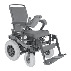
Meyra 2.322 User manual

en
Operating manual
Electric wheelchair
Model 2.322 OPTIMUS 2

2
Contents
Meaning of the applied markers 7
Introduction 7
List of models 7
Indications / contraindications 8
Acceptance 8
Intended purpose 8
Use 9
Adjustment 9
Combination with manufacturer foreign products 10
Reinstallment 10
Life span 10
Base position 10
Overview 11
Model 2.322 11
Handling the electric wheelchair 12
Securing the electric wheelchair 12
Functional checks 12
Driving 12
Brakes 12
Service brake 12
Braking the wheelchair 12
Emergency braking 12
Parking brake 12
Drum Brake 13
Locking the brakes 13
Releasing the brakes 13
Drive-/push mode 14
Selecting the push mode 14
Selecting the motor mode 14

3
Selecting the operation 15
Pre-operation checks 17
Battery charging procedure 17
Positioning the operating module 18
Function description 18
Adjusting the distance to the padded arm support 18
Removing the operating module 18
Inserting the operating module 18
Swivelling the operating module 19
Height adjustment of the operating module 19
Leg supports 20
Calf belt 20
Removing the calf belt 20
Attaching the calf belt 20
Length adjustment of the calf belt 20
Lower leg support 21
Footplates 21
Footboard 21
Leg support upper part 22
Turning the leg supports to the side 22
Swivelling in the leg supports 23
Removing the leg supports 23
Attaching the leg supports 23
Mechanically height-adjustable leg supports 24
Lifting/lowering the leg support 24
Electrically height-adjustable leg support 25
Height adjustment 25
Removing the electrically height adjustable leg support 26
Hanging the electrically height adjustable leg support into place 26

4
Arm supports 27
Arm supports, code 106 27
Removing the arm support 27
Inserting the arm support 28
Arm supports code 24 - Ergostar seat 28
Swivel up the arm supports 28
Adjusting the angle of the arm support 28
Seat 29
Swivelling up the seat 29
Electrical seat-angle adjustment 29
Seat Ergostar 30
Adjustment of the back support angle 30
Lordosis adjustment 30
Ergo Seat 31
Folding down the back support 31
Unfolding the back support 31
Adjusting the back support angle 31
Electrically adjustable back support 32
Folding down the electrically adjustable back support 32
Unfolding the back support 32
Head support 33
Seating system ERGO Seat 33
Retaining strap 34
Rear-view mirror 35
Removing the rear-view mirror 35
Attaching the rear-view mirror 35
Adjusting the rear-view mirror 35
Walking aid holder 35
Lighting 36

5
Loading and transportation 37
Loading 37
Ramps and lifting platforms 37
Transport of people inside a motor vehicle 37
Transport security 38
Tyres 39
Maintenance 39
Maintenance 39
Maintenance schedule 40
Fuses 42
Replacing the fuses 42
Lighting 43
Adjusting the headlights 43
Fault correction 44
Basic safety information 45
Accompanying person 45
Transfer out of the electric wheelchair 45
Reaching for objects 46
Driving on falling, rising or transverse gradients 46
Crossing obstacles 46
Electrical system 47
Transport in public methods of transportation 47
Driving on public highways 48
Cleaning 48
Finish 49
Disinfection 49
Repairs 50
Repairs 50
Customer Service 50
Spare parts 50
Information for extended pauses of use 50
Disposal 50

6
Technical data 51
Tyre pressure of pneumatic tyres 51
Maximum range 51
Hill climbing ability 52
Applied norms 52
Values acc. to ISO 7176-15 for model 2.322 53
Further technical data for model 2.322 54
Dimensions with Ergoseat (Code 948 / 950 without head support): 56
Dimensions with seat Ergostar (Code 961 without head support): 57
Meaning of the symbols on the washing instruction 58
Meaning of the labels on the electric wheelchair 59
Meaning of the symbols on the type plate 60
Inspection certificate 61
Warranty / Guarantee 62
Warrantee / Guarantee section 63
Inspection certificate for transfer 63

7
MEANING OF THE AP-
PLIED MARKERS
Safety instructions with a coloured back-
ground are mandatory and need to be
observed under any circumstance!
☞This symbol indicates tips and recom-
mendations.
[ ] Reference to a picture number.
( ) Reference to a function element within
a picture.
INTRODUCTION
Read and observe this manual before first
operation.
Children and juveniles should read this
documentation together with their par-
ents respectively a supervisor or accom-
panying person before first use.
This operating manual is to help you get
accustomed to the handling of the electric
wheelchair as well as to prevent accidents.
☞Please note that the illustrated equip-
ment variants can deviate from your
model.
We have therefore also listed chapters with
options that might not be applicable for
your individual electric wheelchair. A list of
the available options and accessories can
be viewed in the order form of your electric
wheelchair.
Users with visual impairments can find the
PDF-files together with further information
on our website:
< www.meyra.com >.
☞Contact your specialist dealer when re-
quired.
Alternatively users with visual impairments
can have the documentation read out by a
helper.
Inform yourself regularly about product
safety and possible recalls of our products
in the < Information center > on our website:
< www.meyra.com >.
We have developed an electric wheelchair
that complies with the technical and gov-
ernmental regulations of medical devices.
For information about a severe accident
that can still not be ruled out completely,
please use our E-mail address < info@mey-
ra.de > and inform the responsible govern-
mental agency of your country.
LIST OF MODELS
This operating manual applies to the follow-
ing models:
Model 2.322

8
INDICATIONS /
CONTRAINDICATIONS
In case of allergic reactions, skin rashes
and/or pressure sores during the use of
the electric wheelchair sores contact a
doctor immediately.
In order to prevent contact allergies, we
recommend to use the electric wheel-
chair only when wearing clothes.
The functional diversity of your wheelchair
permits application in situations with ex-
treme to fully pronounced limitations in
mobility/walking in case of structural and/
or functional damages to the lower extremi-
ties (u.o. amputation, after-effects of injuries,
musculoskeletal/neuromusculoskeletally
caused motion disorders e.g. through:
– paralysis,
– loss of limbs (leg amputation),
– defective/deformed limbs,
– joint contractures/-damages,
– other diseases.
Also to be observed for individual provision
are the physical and psychological state,
age of the handicapped person as well as
the personal living condition and private
environment.
Every provision, case by case should be
checked, tested and aligned to the indi-
vidual ability limitations caused by the de-
fined disability through an educated person
(medical device consultant, rehabilitation
consultant u.o.). This also includes that
people that show a counter indications to
the named problems in some cases need
to give proof of the cognitive, mental and
moral ability to operate one of the models
shown in the list of models.
The electric wheelchair may not be used in
cases of:
– Cognitive limitations and mental re-
tarding, that rule out the independent
use of the electric wheelchair.
– Limited eyesight, which cannot be
compensated through glasses or other
aids and that lead to limitations in the
day to day.
– Influence of impairing medications (ask
your doctor or pharmacist).
– Circumstances that prevent the individ-
ual use of the control device.
– Extreme limitations in balance and/or
disorders in perception.
– Disability to sit.
☞To these and other possible risk
concerning your electric wheelchair
ask your doctor, therapist or special-
ist dealer.
ACCEPTANCE
All products are checked for faults in the
factory and packed in special boxes.
☞However, we request that you check
the electric wheelchair for possible
transport damage immediately on re-
ceipt – preferably in the presence of the
carrier.
☞The packaging of the electric wheel-
chair should be stored for a further
transport that might become neces-
sary.
INTENDED PURPOSE
The electric wheelchair serves to improve
independent mobility outdoors.

9
USE
Never use the electric wheelchair without
the leg supports and arm support units
mounted!
The electric wheelchair serves solely for
transporting one sitting person. – Other
pulling or transporting uses do not com-
ply with its intended purpose.
The electric wheelchair is applicable on lev-
el, firm surfaces and can be used as follows:
– for indoors (e.g. apartment, day care),
– outdoors (e.g. paved paths in parks).
– Never expose the electric wheelchair to
extreme temperatures and damaging
environmental conditions, such as sun-
light, extreme cold or salty water.
– Sand and other dirt particles can seize
on moving parts and render them with-
out function.
The electric wheelchair offers manifold ad-
justment possibilities to individual vital sta-
tistics.
National regulations might prevent the use
on busses, trains or in aircraft.
☞Inform yourself at the transportation
companies concerning limitations.
☞Before going on a flight clarify the spe-
cific transport conditions with your
flight agency and also the legal regula-
tions concerning transport in a plane in
your country of residence as well as at
your destination.
Only apply the electric wheelchair within
the scope of the specifications and limita-
tion described in chapter Technical data on
page 51.
ADJUSTMENT
Always have adaptation, adjustment or re-
pair work carried out by a specialist dealer.
The electric wheelchair offers manifold ad-
justment possibilities to individual vital sta-
tistics. Before first use an adaptation of the
electric wheelchair and a practical instruc-
tion in the functionalities of your electric
wheelchair should be carried out by your
specialist dealer. The adaptation will take
into account the driving experience, the
physical limits of the user and the main
place of use of the electric wheelchair. Be-
fore first use, check the functionality of your
electric wheelchair.
Should your specialist dealer carry out a
revision/reconditioning or make funda-
mental changes to your electric wheelchair,
without the use of original spare parts, this
under certain conditions may result in a re-
marketing of your electric wheelchair. This
will further entail that your specialist dealer
might need to conduct new conformity as-
sessments and tests.
☞We recommend a regular inspection of
the electronic wheelchair adjustment
in order to ensure a long-term optimal
provision even with changing illness/
handicap patterns of the user. Especial-
ly for juveniles an adjustment every 6
months is recommendable.
☞We recommend regular medical exams
in order to ensure safety for active par-
ticipation in traffic.

10
COMBINATION WITH MAN-
UFACTURER FOREIGN
PRODUCTS
Any combination of your electric wheelchair
with components not supplied by us gener-
ally results in an amendment to your electric
wheelchair. Please inquire with us if there is
a valid combination clearance/release.
REINSTALLMENT
The electric wheelchair is suited for reinstall-
ment. With the building block system the
electric wheelchair can be fit to accommo-
date different handicaps body sizes. Before
reimplementation the electric wheelchair is
to undergo a complete inspection.
☞Hygienical measures required for rein-
stallment are to be carried out accord-
ing to a validated hygienic plan and
must include disinfection.
The service manual, intended for the spe-
cialist dealer provides information to the re-
installment and reinstallment frequency of
your electric wheelchair.
LIFE SPAN
We expect an average life span of about
5 years for this product, as far as the product
is applied for its designated purpose and all
maintenance and service guidelines. The life
span of your product depends upon the fre-
quency of use, the application environment
and care. The implementation of spare parts
can prolong the life span of the product. As
a rule spare parts are available up to 5 years
after production is discontinued.
☞The indicated lifespan does not consti-
tute additional guarantee.
BASE POSITION
Only drive on slopes, inclines and obsta-
cles in the basic position of the seat rising
function, back inclination and seat angle.
– Danger of overturning!
Basic position is to be understood as:
– Seat height adjustment in the lowest
position.
– Back inclination in upright position.
– Seat inclination in horizontal position
(but max 10°).

13
15
16
13
1 2 3
4
5
6
789
10
11
12
14
11
OVERVIEW
Model 2.322
The overview shows the most important
components and operating devices of the
electric wheelchair.
Pos. Description
(1) Back support
(2) Arm support
(3) Seat
(4) Leg support
(5) Seat lock
(6) Calf belt
(7) Footplate
(8) Headlights
(9) Driving wheel
(10) Steering wheel
(11) Front indicator
(12) Operating module
(13) Selection lever drive/push mode resp.
brake lever
(14) Type plate
(15) Direction indicator light / back light
(16) Rear transport attachment

12
HANDLING THE ELECTRIC
WHEELCHAIR
Securing the electric wheelchair
The electric wheelchair is to be secured as
follows to prevent it from rolling off unin-
tentionally:
1. Swivel the selection lever drive- / push
mode to drive mode.
2. Switch off the operating module.
Functional checks
The functions and safety of the electric
wheelchair must be checked before the
start of each journey.
☞For this observe chapter < Inspections
before starting to drive > in the accom-
panying documentation.
Driving
You define the speed and direction yourself
with the joystick movements (driving and
steering lever) while driving as well as the
preadjusted maximum final speed of your
electric wheelchair.
BRAKES
Brake the electric wheelchair down care-
fully and in time. This is especially the case
when driving in front of people and while
driving downhill!
Service brake
The motor works electrically as an oper-
ating brake and decelerates the electric
wheelchair softly and jerk-free to a standstill.
Braking the wheelchair
For allotted braking of the wheelchair slow-
ly guide the joystick (steering and driving
lever) back to the centre position (zero-set-
ting).
Emergency braking
☞The electric wheelchair stops in short-
est distance after releasing the joysticks.
Parking brake
The parking brake only has effect when the
brake lever of the drum brake is swivelled
backwards.

1
2
13
Drum Brake
For optimal braking effect the drum brake
is to be kept free of grease, oil, gunge and
dust. – Danger of accidents!
The brake performance reduces with the
wear on the brake pads.
Any decrease in braking performance
must be repaired immediately by your
specialist workshop.
The optional drum brake only serves as a
parking brake, resp. emergency brake.
The brake lever to engage the drum brake
is located on the same side as the operating
module.
Locking the brakes
The electric wheelchair may not let itself
be pushed when the brake is activated.
In order to engage the brakes, swivel the
brake lever toward the back as far as pos-
sible [1].
Releasing the brakes
Only transfer into or out of the electric
wheelchair when the electric wheelchair
is switched off and the selection lever
drive-/push mode on both sides is in drive
mode!
An unintentional movement of the joy-
sticks (driving and steering lever) can
otherwise lead to an uncontrolled start of
the electric wheelchair! – Danger of acci-
dents!
In order to disengage the brakes, swivel the
brake lever toward the front as far as possi-
ble [2].

1
2
4
3
14
Drive-/push mode
Only switch the electric wheelchair to
push mode when it is standing still for
positioning or in case of emergencies, but
not on slopes/hills.
When establishing drive-/push mode,
watch for jamming areas!
The selection lever drive/push mode is lo-
cated on the side opposite to the operating
module.
☞The electromagnetic brake is switched
off when push mode is activated.
– Then the electric wheelchair can only
be braked by switching to drive mode
or by activating the drum brake.
☞For shunting the electric wheelchair
grab hold on the push bar of the back
support or the back support itself.
Selecting the push mode
1. Switch off the operating module be-
cause the pushing will otherwise be
made difficult by the electric system.
☞Therefore observe operation manual
< Operating module >.
2. First pull up the locking sleeve (2) on
the selection lever drive/push mode,
then guide the selection lever toward
the back [3].
☞Therefore observe chapter Releasing
the brakes on page 13.
The electric wheelchair can now be pushed.
Selecting the motor mode
1. Guide the selection lever drive/push
mode forward and let it audibly lock
into place [4].
☞Therefore observe chapter Releasing
the brakes on page 13.
2. Switch the operating module on.
☞Therefore observe operation manu-
al < Operating module >.
The electric wheelchair is now ready for use
again.

2
1
15
SELECTING THE
OPERATION
In order to obtain operational readiness of
the electric wheelchair the following direc-
tions are to be carried out in the indicated
order.
☞Charge the drive batteries via the oper-
ating module before the first journey.
1. Establish drive mode [1].
☞Therefore observe chapter Technical
data on page 51.
2. Loosen the drum brake [2].
☞Therefore observe chapter Drum
Brake on page 13.

4
23
16
3. Position of the operating module
The maximum extension reached, when
a mark becomes visible in the receptacle
tube of the operating module.
☞The operating module should be
positioned in such a way that you
can comfortably and safely steer the
electric wheelchair.
☞The distance of the operating mod-
ule to the padded arm supports
can be adjusted after loosening the
clamping screw (3).
4. After the adjustment retighten the
clamping screw.
☞For this observe chapter Positioning
the operating module on page 18.
5. Switch the operating module on
☞Press the On/Off-key (4) on the con-
trol panel of the operating module.
☞Therefore observe operation manu-
al < Operating module >.

1
2
17
Pre-operation checks
Before starting to drive, the following should
be checked:
☞the battery charging condition,
☞the setting of the preselected final
speed.
– For this observe the operating manual
< Operating module >.
Battery charging procedure
Do not insert any objects other than the
battery charger plug into the battery
charging socket. – Danger of short circuit!
Only charge the batteries in well aired, dry
rooms.
Protect the charger from heat, dampness,
drop and spray water and jamming since
it contains voltage. – Short circuit- and
mortal danger!
Ensure a good ventilation of the charger
during the charging (do not cover) in or-
der to dissipate the heat generated by the
charger. – Danger of fire!
Place the battery on a firm surface for
charging.
Do not put the charger on the seat of the
electric vehicle for charging.
Do not smoke and avoid open flame or
sparking when handling cables and elec-
tric devices. The charging gases that can
be produced by the charging are always
explosive.
Avoid spark build up through electrical
static (for example caused by synthetic
floor covers).
☞For the battery charging procedure also
observe the operating manual of the
battery charger.
1. Lock the electric wheelchair.
☞Therefore observe chapter Securing
the electric wheelchair on page 12.
2. Insert the charger plug into the battery
charging socket (1) of the operating
module.
3. Switch the battery charger on, resp.
insert the main plug of the battery
charger into the corresponding power
socket.
☞The charging procedure is initiated.
☞The charging procedure only runs
with an intact mains/battery fuse
(2)!
4. After a completed charging procedure
disconnect the battery charger from
the socket and remove the battery
charging plug from the battery charg-
ing socket.

21
4
3
18
Positioning the operating module
Switch off the operating module before
adjusting/removing it.
Function description
You will find a detailed description of the
keys and symbols in the operating manual
for < Operating module >.
The position of the operating module can
be adjusted to suit the individual size of the
user. The operating module can also be
removed for transportation or storage and
can be laid on the seat or stored separately.
Adjusting the distance to the padded
arm support
Switch off the operating module before
adjusting/removing it.
The maximum extension reached, when
a mark becomes visible in the receptacle
tube of the operating module.
Slacken the clamping screw distance ad-
justment (1). Afterwards slide the operating
module into the desired position. In doing
so carefully guide the cable and retighten
the clamping screw (1) securely.
Removing the operating module
In order to remove the operating module
loosen the clamping screw (1) and discon-
nect the plugged connection (2) (4).
☞Do not pull on the cable while do-
ing so.
Afterwards pull out the operating module
toward the front out of the arm support
tube.
Inserting the operating module
Watch for possible jamming areas when
plugging in the operating module..
For drive mode insert the operating module
from the front into the arm support tube [3]
and adjust the distance to the padded arm
support.
☞Therefore observe chapter Adjusting
the distance to the padded arm sup-
port on page 18.
Afterwards re-establish the plugged con-
nection (4) (2).
☞The plugged connection must au-
dibly lock into place. – Afterwards
check the function of the operating
module.

1
2
33
4
19
Swivelling the operating module
Do not grab into the area of the cross
brace. – Danger of squashing!
With the optional swivel away operating
module adapter [1] the operating module
can be swivelled back to the side (2) so that
it is located parallel to the arm support. This
makes it possible, for example:
– to drive closer to a table,
– remove the operating module more
easily.
For regular drive mode the operating mod-
ule can be swivelled back toward the front
until it engages back into the magnetic lock
[1].
☞The power of the magnets (3) can be
reduced, for example with tape on top
of the magnets, for easier swivelling of
the operating module.
☞Should the operating module be po-
sitioned too close to the arm support,
move it forward before swivelling.
Height adjustment of the operating
module
Loosen the clamping screw (4) to adjust the
height of the operating module.
☞After the adjustment retighten the
clamping screw.

1
3
2
4
20
LEG SUPPORTS
Before any actions on the leg supports
the electric wheelchair is to be secured
against unintentional rolling motions.
☞Therefore observe chapter Securing the
electric wheelchair on page 12.
Calf belt
Do not drive without the calf belt. – Dan-
ger of accidents!
The removable calf belt (1) prevents the feet
from sliding off the back of the footplates.
☞The calf belt must be removed in order
to swivel away the leg supports [2].
☞The calf belt is omitted for height ad-
justable leg supports and is replaced by
a calf pad.
Removing the calf belt
For removal the calf belt is to be pulled from
the attachment pins (3).
Attaching the calf belt
For attachment both loops of the calf belt
are slid over the attachment pins [4].
Length adjustment of the calf belt
For length adjustment, the calf belt is guid-
ed around the special attachment pins (3)
and adjusted in length with a velcro fasten-
er.
Other manuals for 2.322
2
Table of contents
Other Meyra Wheelchair manuals

Meyra
Meyra 2.845 User manual

Meyra
Meyra Eurochair2 2.750 User manual
Meyra
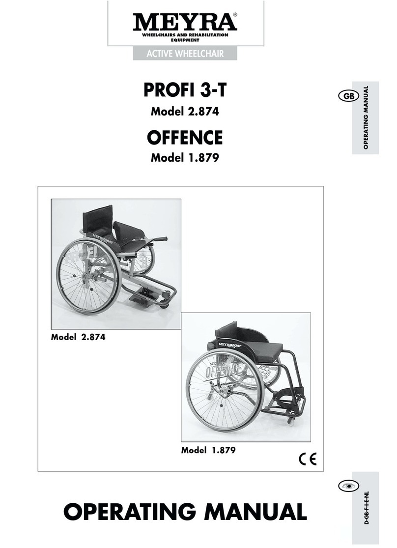
Meyra PROFI 3-T 2.874 User manual
Meyra
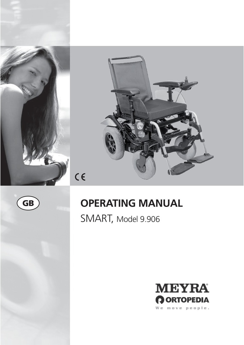
Meyra SMART 9.906 User manual
Meyra
Meyra 1.610 Manual
Meyra
Meyra Netti DYNAMIC AdaptPro User manual
Meyra
Meyra 2.360 Manual

Meyra
Meyra 9.050 User manual

Meyra
Meyra 1.650 iCHAIR MEYLIFE User manual

Meyra
Meyra 1.135 User manual
Meyra
Meyra 1.620 User manual

Meyra
Meyra 2.360 User manual

Meyra
Meyra 1.620 User manual

Meyra
Meyra MOTIVO 2.250 User manual

Meyra
Meyra 1.595-603 User manual
Meyra
Meyra 1.736 User manual

Meyra
Meyra 1 612 iCHAIR MC3 27 Use and care manual
Meyra
Meyra FX One 1.150 User manual

Meyra
Meyra 1.750 User manual
Meyra
Meyra 1.611 User manual

