Meyra Sprint Operating instructions

1
ELECTRONIC–WHEELCHAIR
Special operating instructions
formodel
Sprint, Euro-Sprint, Sprinti, Optimus
Wheelchairs and Rehabilitation Aids

2
SPECIAL OPERATING INSTRUCTIONS
OPERATING DEVICE
UNIVERSAL INTERFACE
EXTERNAL ON/OFF BUTTON (EMERGENCY
STOP)
EXTERNAL JOYSTICK
ADAPTER
TABLE-OPERATED VERSION
CHIN-OPERATED VERSION
FOOT-OPERATED VERSION
EXTERNAL KEYBOARD OPERATION
FINGER-OPERATED JOYSTICK
CENTRAL OPERATION
OPERATING DEVICE SUPPORT
TETRAGONAL LEVER
EXTERNAL DRIVE KEY SOCKET / CHARGING
SOCKET
SPECIAL OPERATING MATRIX

3
CONTENTS
LCD operating device, Code 416 4
Function options by pressing two buttons.....................................................................5
Function options by pressing two buttons and the service socket...................................... 9
Function options offered by service programmes ........................................................ 10
Universal interface 11
External ON/OFF button, Code 543 13
Externaljoystick, Code 542 15
Thumb-operated joystick, Code 536 17
Adapter 18
Table-operatedversion 19
Table-operatedversion,Code813 ..............................................................................21
Multifunctional table-operated version, Code 544 ....................................................... 22
Table-operated version, Code 548............................................................................. 23
Specialtable-operatedversion .................................................................................. 24
Chin-operated version 25
Chin-operatedversion,Code812 ............................................................................. 26
Operating instructions for chin-/foot-operated version and mini joystick 28
Multifunctional chin-operated version, Code 540 .......................................................30
Operation using the back of the head........................................................................ 33
Foot-operated version 34
Foot-operated version Code 546 .............................................................................. 35
Operating instructions for chin-/foot-operated version and mini joystick 36
Multifunctional foot-operated version, Code 547 ......................................................... 37
External keyboardoperation 38
Minijoystick, Code 541..........................................................................................39
Operating instructions for chin-/foot-operated version and mini joystick 40
Custom-made external buttons 41
Specialjoystick 45
Finger-operated joystick, Code 549 46
Central operation, Code 50 48
Operatingdevicesupport,Code 851 49
Tetragonallever,Code556 50
External drive keysocket/chargingsocket,Code545 51
Combination of special operating features 52

4
LCD OPERATING DEVICE, CODE 416
The special operating concept
is designed in such a way that
each standard wheelchair can
be easily adapted to the require-
ments of its respective disabled
user. Wichtig für die Adaption
der Sonderbedienungen ist, daß
der Rollstuhl mit dem
Stan-
dard-LCD-Bediengerät,
CODE 416
. This operating de-
vice has an integrated 8-pole
service socket serving as a con-
nection for all of the special
operating features. ( Plug and
Play )
Service sok-
ket
MODE
The following special operating features are offered by MEYRA as standard special operating fea-
tures. Deviations and modifications are possible on request.
Many special operating features are made possible via easy adaptation via the serial interface in the
standard operating device which also complies with international standards. This area is subject to
ongoing improvements and developments.
Please contact your sales clerks if you have any queries.

5
Function options by pressing two buttons
The standard operating device already
integrates some special options which
can be selected by pressing two but-
tons, e.g. horn signal phase, display
background lighting, button operation
via the joystick etc. These functions are
described in detail below.
LCD BACKGROUND LIGHT-
ING
The LCD has background lighting to facil-
itate interpretation of the display.
Activating the LCD background lighting
– The wheelchair is ready to start and
secured.
– The LCD display shows the speed
indication.
–
Keeping the
button pressed
press
the
ON/OFF button at the same time
.–
The wheelchair switches off.
Deactivating the LCD background lighting
– The wheelchair is ready to start and
secured.
– The LCD display shows the speed
indication.
–
Keeping the
button pressed
press
the
ON/OFF button at the same time
.–
The wheelchair switches off.
HORN SIGNAL PHASE
The automatic horn signal phase while
indicating or reversing can be switched
ON/OFF.
Activating the horn signal phase
– The wheelchair is ready to start and
secured.
– The LCD display shows the speed
indication.
–
Keeping the
button pressed
press
the
ON/OFF button at the same time
.–
The wheelchair switches off.
Deactivating the horn signal phase
– The wheelchair is ready to start and
secured.
– The LCD display shows the speed
indication.
–
Keeping the
button pressed
press
the
ON/OFF button at the same time
.–
The wheelchair switches off.
Note:
Switching off
following data
entry
automatically saves the new data
.
Which becomes effective once the
control box is switched back on
again.
Note:
The
horn signal phase
can be select-
ed
in an even more
detailed manner
using
the Service Programme
.
The Service Programme is included in
the Diagnosis Pack, article no. 1
024 869.
Note:
Switching off
following data
entry
automatically saves the new data
.
Which becomes effective once the
control box is switched back on
again.
Note:
The
LCD background lighting
can be
switched ON/Off via the Service Pro-
gramme
.
The Service Programme is included in
the Diagnosis Pack, article no.
1024869.
LCD OPERATING DEVICE, CODE 416

6
MULTIFUNCTIONAL OP-
ERATION
The multifunctional operating feature per-
mits the user to operate all of the control
and button functions (with the exception
of the ON/OFF button) via the control
and steering lever
and can only be set at
the LCD control box
.
Converting to multifunctional operation
1. Switch on the control box. – The
speed will appear in the display. The
multifunctional operating feature is
active once "F H" appears in the dis-
play.
2. Keep the "Indicator left" button
pressed.
3. Press the "ON/OFF" button and re-
lease. – The wheelchair switches off.
4. Now release all of the buttons.
5. Switch on the control box. – "F H" ap-
pears in the display. – The multifunc-
tional operating feature is active.
Once the control box is switched off, one of the two LCD displays
appears.
Button operation active Multifunctional operation active
F = Drive mode
H = Help mode
Note:
Repeat steps 1 to 5 to convert back
to standard button operation.
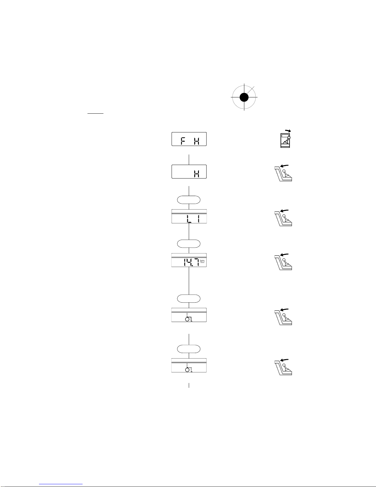
OPERATING INSTRUC-
TIONS FOR
MULTIFUNCTIONAL OP-
ERATION
"F H" appears in the display when the con-
trol box is switched on.
Pushing the drive
and steering lever to-
wards
the right activates Help mode. –
A
"H" appears in the display
.
Functions of the drive and steering lever
in Help mode
VV
VV
V = Push drive
and steering lever for-
wards
.
LL
LL
L = Push drive
and steering lever to the
left
.
RR
RR
R = Push drive
and steering lever to the
right
.
HH
HH
H = Push drive
and steering lever back-
wards
.
Pressing the MODE function loads the
next possible setting. The setting appearing in the display can be
changed or skipped by pressing the
MODE function again.
Operating the horn.
Setting the trip mileage display at "Zero". To set the trip mileage display at "Zero",
the drive and steering lever should be
moved forwards several times until the
trip mileage counter appears in the dis-
play.
Changing the setting option selected.
Changing the setting option selected.
Note!
For safety reasons, settings should
be made when the wheelchair is sta-
tionary!
V
h
r
lDangerof overturning on gradients and
obstacles avoided by adjusting angles!
JJoystick seen vv
v from above
The standard operating device also offers assistance to disabled users who are unable to operate the keyboard at no extra
charge. By pressing two buttons, a special programme is set permitting operation of all of the keyboard functions (with the excep-
tion of the ON/OFF button) using the control joystick (e.g. lights, electric adjustments). The so-called multifunctional operating
feature is indicated by "F H" in the operating device display.
LCD OPERATING DEVICE, CODE 416
7
Handling:
1. Switch on the control box. – "F H" ap-
pears in the display. If the speed dis-
play appears, please refer to "Con-
verting to multifunctional operation".
V
h
R
l
Joystick
Display JJoystick function
Multifunctional operation active
V
= Drive mode
R
= Help mode
L
= Drive mode
H
= Drive mode
2. Move the drive and steering
lever to
the right (R)
. – A "H" appears in the
display indicating Help mode.
Indicator
Change setting via the joystick. Help mode active
V
= MODE function
R
= Indicator right
L
= Indicator left
H
= Horn
3. Move the drive and steering
lever to
the front (V)
. – Pressing the MODE
function loads the next possible set-
ting.
Light
Change setting via the joystick.
MODE
V
= MODE function
R
= Switch on light
L
= Switch off light
H
= Horn
4. Move the drive and steering
lever to
the front (V)
. – Pressing the MODE
function loads the next possible set-
ting.
Pre-select the trip mileage counter v v
andend speed
Change setting via the joystick.
MODE
V
= MODE function
R
= Increase end speed
L
= Reduce end speed
H
= Set trip mileage counter display
at "Zero"
5. Move the drive and steering lever tolever to
lever tolever to
lever to
the front (V)the front (V)
the front (V)the front (V)
the front (V). – Pressing the MODE
function loads the next possible set-
ting.
Adjusting the backrest
Change setting via the joystick.
MODE
V
= MODE function
R
= Angle adjustment to
max. 45°
L
= Back to starting position
H
= Horn
Depending on the wheelchair's equip-
ment
6. Move the drive and steering lever tolever to
lever tolever to
lever to
the front (V)the front (V)
the front (V)the front (V)
the front (V). – Pressing the MODE
function loads the next possible set-
ting.
Adjusting the seat incline
Change setting via the joystick.
MODE
V
= MODE function
R
= Angle adjustment
to max. 15°
L
= Back to starting position
H
= Horn
Depending on the wheelchair's equip-
ment
continued on next page!
LCD OPERATING DEVICE, CODE 416

8
V
h
R
l
Joystick
Handling:
Display JJoystick function
7. Move the drive and steering lever tolever to
lever tolever to
lever to
the front (V)the front (V)
the front (V)the front (V)
the front (V). – Pressing the MODE
function loads the next possible set-
ting.
Leg support angle, right
Change setting via the joystick.
V
= MODE function
R
= Angle adjustment
to max. 60°
L
= Back to starting position
H
= Horn
Depending on the wheelchair's equip-
ment
MODE
8. Move the drive and steering lever tolever to
lever tolever to
lever to
the front (V)the front (V)
the front (V)the front (V)
the front (V). – Pressing the MODE
function loads the next possible set-
ting.
Leg support angle, left
Change setting via the joystick.
V
= MODE function
R
= Angle adjustment
to max. 60°
L
= Back to starting position
H
= Horn
Depending on the wheelchair's equip-
ment
MODE
9. Move the drive and steering lever tolever to
lever tolever to
lever to
the front (V)the front (V)
the front (V)the front (V)
the front (V). – Pressing the MODE
function loads the next possible set-
ting.
Total mileage display
Display can not be changed, contin-
ue with
V
= MODE function
R
=––
L
=––
H
= Horn
MODE
10. Move the drive and steering lever tolever to
lever tolever to
lever to
the front (V)the front (V)
the front (V)the front (V)
the front (V). – Pressing the MODE
function loads the next possible set-
ting.
Automaticbreak time
Change setting via the joystick.
V
= MODE function
R
= Increase
L
= Reduce
H
= Horn
MODE
11. Move the drive and steering lever tolever to
lever tolever to
lever to
the front (V)the front (V)
the front (V)the front (V)
the front (V). – Pressing the MODE
function loads the next possible set-
ting.
Drive or Help mode
MODE
Multifunctional operation active
V
= Drive mode
R
= Help mode
L
= Drive mode
H
= Drive mode
LCD OPERATING DEVICE, CODE 416

9
Changing the steering direction when reversing
It is possible for the wheelchair to move like a standard dual-motor wheelchair when reversing:
Drive lever moved backwards to the left
> Curving towards the back right, or like a standard single-motor wheelchair:
Drive lever moved backwards to the left
> Curving towards the back left.
Handling:
– Insert the service plug in the control box service socket and switch on the wheelchair.
– Press the "MODE" and the "ON/OFF" buttons at the same time.
The change in direction is activated once the wheelchair is switched on again.
Available from microprocessor "IC1.0 W" (approx. October1996) in the LCD board in the control
box.
Changing direction
There is a choice of travelling "forwards" (standard setting) or "reverse" when the wheelchair's drive lever is
movedforwards.
Some users find it easier to pull the drive lever backwards rather than push it forwards. This group of
users has the option of travelling forwards by pulling the drive lever backwards, i.e. towards them.
Steering of the wheelchair is unaffected by this.
Handling:
– Insert the service plug in the control box service socket and switch on the wheelchair.
– Press the "Hazard light" and the "ON/OFF" buttons at the same time.
The change in direction is activated once the wheelchair is switched on again.
Available from microprocessor "IC1.0 W" (approx. October1996) in the LCD board in the control
box.
Function options by pressing two buttons and the service socket
The service socket facilitates changes in direction as well as the direction of steering in the case of the
sprint models.
LCD OPERATING DEVICE, CODE 416

10
DELAYING THE STARTING
TIME
The time between moving the joystick
and the wheelchair starting off can be set
smoothly from 0 to 3 seconds (e.g. for
spastic users).
Note:
This delay in the starting time can
only be set using the SERVICE Pro-the SERVICE Pro-
the SERVICE Pro-the SERVICE Pro-
the SERVICE Pro-
grammegramme
grammegramme
gramme and a PC.
Settings can also be made by
MEYRA.
Function options offered by service programmes
SECURING USING THE LCD
COMBINATION LOCK
The user can secure the SPRINT and the
OPTIMUS against unauthorised use via
a freely-selectable three-digit combina-
tion.
Benefits:
– Securing against unauthorised use.
– Programming the respective user's per-
sonal number combination prevents. -
The number combination being forgot-
ten as it is freely selectable.
– The combination lock can be deacti-
vated. -In the case of alternating users.
Handling:
– The combination lock can be pro-
grammed using the Service Pro-
gramme and a PC,
or
– by MEYRA.
1. Switch on the control box. – Three ze-
ros appear in the LCD.
Note:
Please familiarise yourself
with this
combination of digits
and keep it to
hand
at all times.
– This will make
matters easier in the event of the user
forgetting the combination or if own-
ership of the wheelchair changes
hands.
Remark:
The speed is displayed in the LCD once
the control box is switched on:
– The combination lock is deactivat-
ed (please refer to "Activating the
combination lock").
– No combination lock has been
programmed yet.
Deactivating the combination lock
1. The wheelchair is ready to start and
secured. – The LCD display shows
the speed indication.
2.
Keep the right-hand indicator pressed
and press
the ON/OFF button at the
same time
. – The wheelchair switches
off.
Activating the combination lock
1. The wheelchair is ready to start and
secured. – The LCD display shows
the speed indication.
2.
Keep the right-hand indicator pressed
and press
the ON/OFF button at the
same time
. – The wheelchair switches
off.
Note:
The Service Programme is included in
the Diagnosis Pack, article no. 1 024
869.
Note:
Three zeros appear in the LCD:
2. Set the desired number combination
by pressing the and buttons.
3. Once the third digit has been entered,
the LCD automatically changes to the
speed display.
LCD OPERATING DEVICE, CODE 416
Note:
Switching off
following data
entry au-
tomatically saves the new data
. Your
entry will be effective when the con-
trol box is switched on again.
11
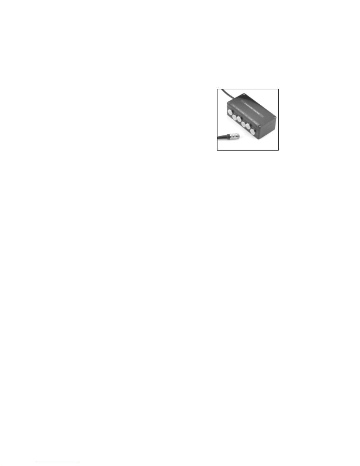
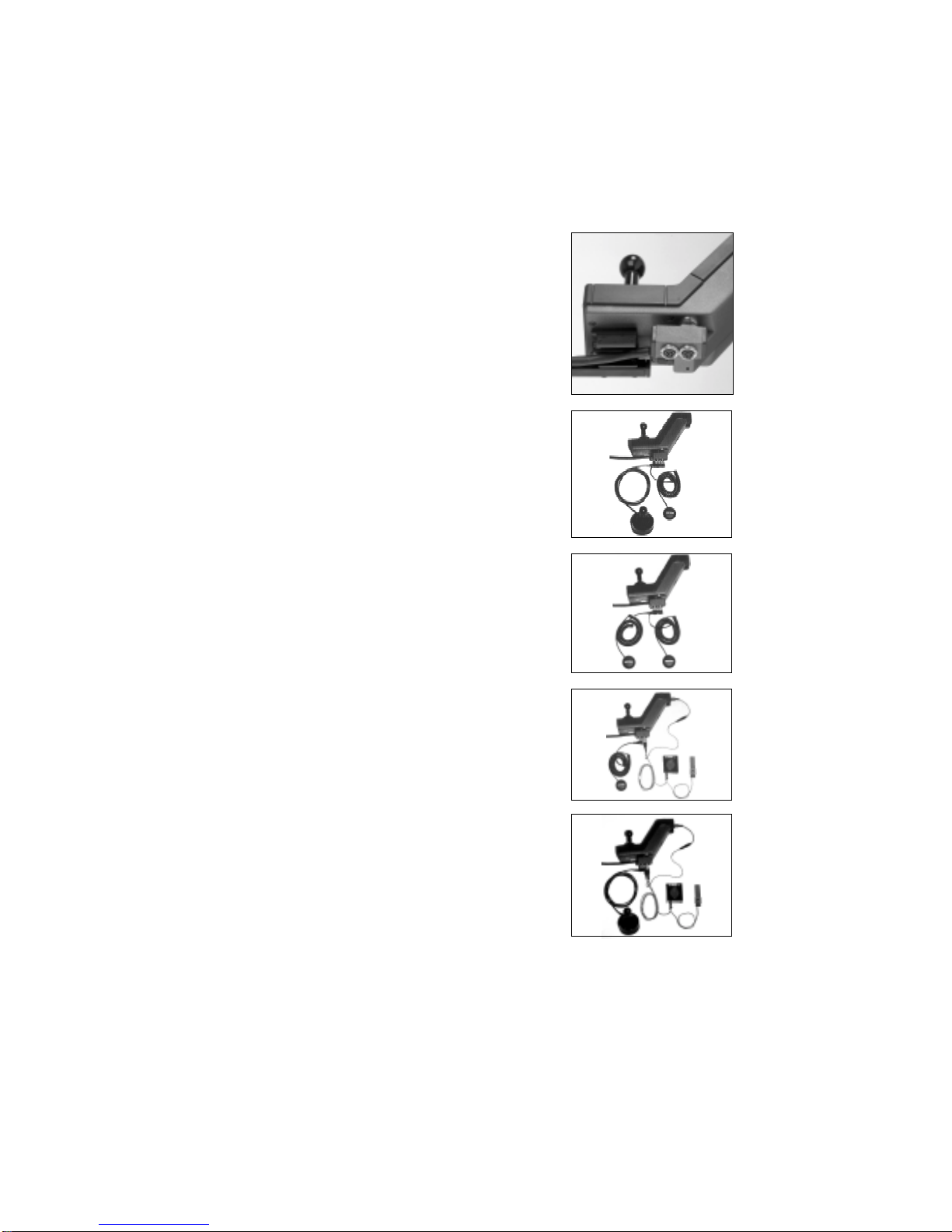
UNIVERSAL INTERFACE
In connection with the universal interface (article no. 1 041 220),
all of the special operating features with the standard LCD opera-
ting device can be easily installed.
Special operating features can also be easily and practically combi-
ned.
And the standard operating device remains operable as before.
Scope of supply:
1. A universal interface
2. An assembly kit comprising:
2x M4 x 8 mm recessed head screws
2x M4 drive-in nuts
10x black cable binders
2x Velcro strips
1x Assembly Instructions
Operating instructions:
The universal interface is a box with a connecting cable and 6 marked plug-in sockets. The connecting
cable should be screwed into the LCD operating device's service socket when the wheelchair is swit-
ched off. Then screw the desired special operating feature(s) into the appropriate socket(s).
SocketsSockets
SocketsSockets
Sockets FunctionFunction
FunctionFunction
Function CODECODE
CODECODE
CODE
I/O External On/Off button 543
EXT buttons External keyboard, please refer to Table operation 548
Chin/Foot/Mini Chin operation 812
Foot operation 546
Mini joystick 541
Tr.B. Trackball, Computer pad
EXT Joystick 2 Multifunctional chin operation 540
Externer Joystick 542
Multifunctional table operation 544
Multifunctional foot operation 547
Table-operated joystick 548
EXT Joystick 1 See above, only with maximum priority
A priority switching feature is integrated for the event that several of our special operating features are
activated simultaneously.
Maximum priority: 1. EXT joystick 1( socket on extreme right )
2. EXT joystick 2
3.Chin/Foot/Mini
4. MOUSE/TRACK/PAD

12
The universal interface box is mounted either using Velcro strips or screws.
Mounting using Velcro strips
Stick the two Velcro strips onto the back of the interface box parallel to the top and bottom edges. The
area must be free of dust and grease before attaching the Velcro strips.
Mounting using screws
If screws are to be used, open the cover of the interface box in order to mark the drill points in the
corners of the box. Remove the back or seat padding, drill the holes and insert the drive-in nuts.
Screw on the interface box.
Cable management
The connecting cable plug is inserted in the LCD control box service socket from below. . Lay the
cable in such a way that it is not pinched and use the cable binders to secure it.
Depending on the wheelchair configuration or customer requirements, the interface box can be posi-
tioned as follows:
– on the back section,
– under the seat (without electric adjustments),
– onthe inside or outside of the side section (depending on the sidesectionand the customer's seat position)
– behind the plastic cover between the rear lights (in the case of sprint models)
– as required and depending on the space available (when seat frames are supplied)
Assembly:
UNIVERSAL INTERFACE

13
The external ON/OFF button serves as an external ON/OFF
function for disabled users who are unable to operate the keypad
and is supplied in addition to foot and hand operation and/or as a
emergency stop function for carers.
EXTERNAL ON/OFF BUTTON, CODE 543
Scope of supply:
1) large button with 8-pole angle-entry plug
2) assembly kit comprising:
a) Velcro tape (velvet disk)
b) Velcro tape (adhesive disk)
c) clamp
d) loop
e) hexagon socket screw (M5x6)
Connection procedure:
The external ON/OFF button's 8-pole angle-entry plug is scre-
wed into the service socket on the operating device and can be
mounted on the wheelchair as the customer requires.
a
b
c
e
d

14
Examples:
1. Mounted as an external ON/OFF button using Velcro tape on the
right or left armrest, e.g.:
2. Mounted as an external ON/OFF button or an Emergency Stop
button using a clamp on the rear tube for use by a carer
on the armrest pad to the side of the operating device to the side of the armrest pad
3. Mounted as an external ON/OFF button or an Emergency Stop
button using Velcro tape on the Recaro seat for use by a carer.
The Velcro tape is sewn on at the desired position and the button
is attached using the velvet tape.
Individual possibilities for securing the ON/OFF button should be discussed with your local specialist dealer.
MEYRA can offer some assistance where custom-made solutions are required.
EXTERNAL JOYSTICK, CODE 543

15
EXTERNAL JOYSTICK, CODE 542
The external joystick is of interest if the disabled user is unable to reach
the joystick in the operating device or if a carer is to operate the
wheelchair.
Scope of supply:
1) external joystick with 8-pole angle-entry plug
2) assembly kit comprising:
a) clamp
b) 2 hexagon socket screws ( M5x8 )
c) 1 handrest
d) 2 hexagon socket screws ( M5x25 )
e) 2 M5 nuts
f) 1 clamping bracket
Connection procedure:
The external joystick's 8-pole angle-entry plug is screwed into the
service socket on the operating device. When the operating device
is switched on,
EXT
appears in the top of the display and the
wheelchair is then ready to start via the external joystick, too. The
external joystick takes priority.
Examples:
c
f
b
d
d
e
e
a
b
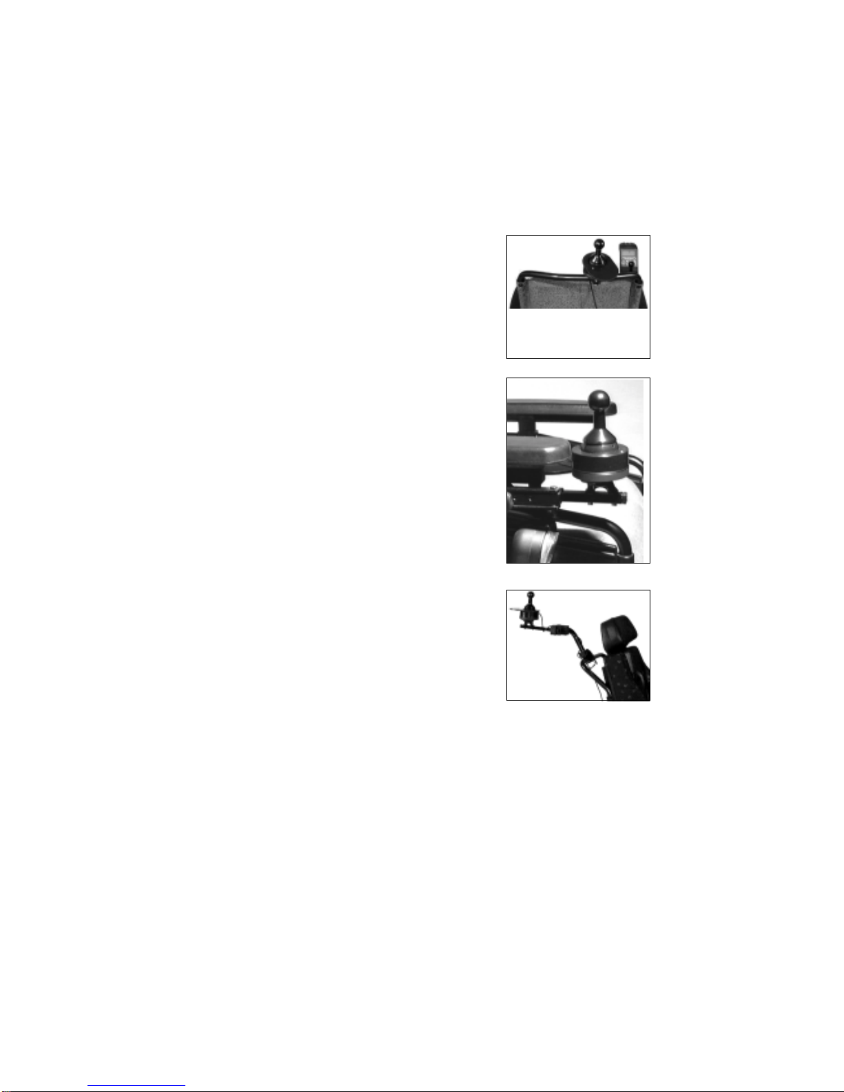
16
1. Mounted as an external joystick on the rear tube for a carer
( Sprint/ Euro Sprint/ Optimus/ Optimus Light )
2. Mountedasanexternaljoystickonthe operating device retaining rod
for the disabled user.
In the case of this application, it would make sense to mount the
operating component on the rear tube using the operating compo-
nent holder, Code 851.
3. Mounted as an external joystick for a carer and
combinedwiththeoperatingcomponentholder,
Code 851.
This mounting variant is practical for the Sprinti in order to achie-
ve the operating height and sufficient clearance from the chair for
the carer.
Note:
Where Recaro seats are concerned, a custom-made sliding handle must be attached in order to facilitate
mounting an external joystick for the carer.
If movement of the arms is restricted, the external joystick or even the operating device can be attached
using custom-made holders. These holders are made by specialist dealers or, following agreement and
the provision of exact specifications, by MEYRA.
Custom-made: external joystick with holder
EXTERNAL JOYSTICK, CODE 542
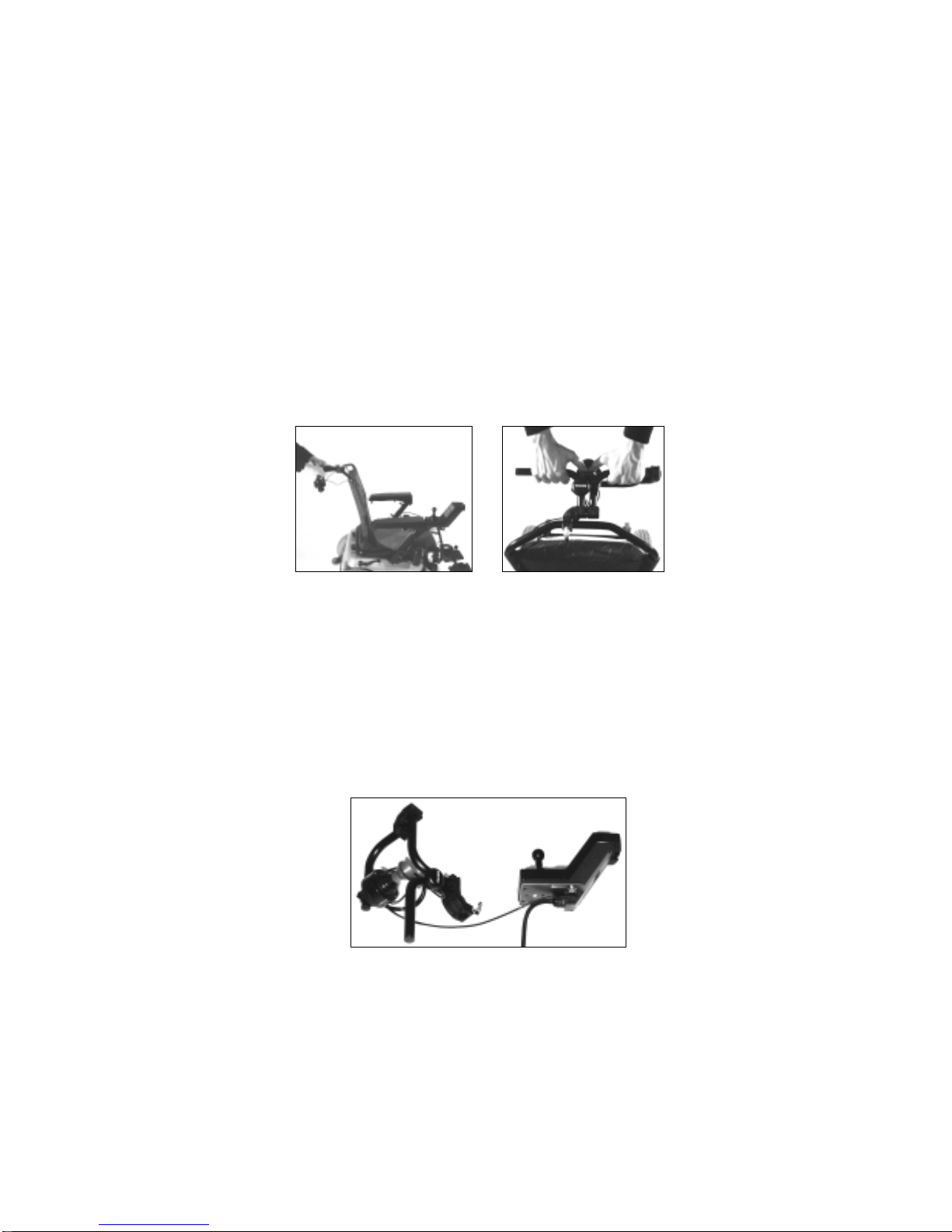
17
MEYRA offers custom-made external joysticks with holders for carers.
The holder is mounted on the rear tube. The carer touches the supporting straps and inserts both
thumbs into the external joystick's funnel-shaped opening. The guides supplied make it considerably
easier for the carer to operate the wheelchair (similar to a shopping trolley).
Connection procedure:
The thumb-operated joystick's 8-pole angle-entry plug is screwed into the service socket on the ope-
rating device. When the external ON/OFF button is switched on
EXT
appears in the top of the dis-
play and the wheelchair is then ready to start via the thumb-operated joystick, too. The thumb-opera-
ted joystick takes priority.
THUMB-OPERATED JOYSTICK, CODE 536
18
ADAPTER
The adapter (article no. 1 036 254) is inserted into the service socket
and two connection sockets permit a combination of the external ON/
OFF button and the external joystick.
Note: Do not connect two external joysticks in parallel!
e.g. external ON/OFF button, Code 543, combined with an externa
e.g. External joystick, Code 542, combined with finger-operated joy-
stick,Code549,viaanadapterwith operating device
Note: Please contact Mr. Papenhoff, tel.
05733/922-
363
Special operating features (multifunctional chin operation, CODE 540,
multifunctionaltable operation, CODE 544, multifunctional foot operati-
on) can also be combined with the external ON/OFF button via the
adapter.
e.g. External ON/OFF button, Code 543, combined with finger-ope-
ratedjoystick, Code 549, via an adapter in the operatingdevice.
e.g. External ON/OFF button, Code 543, combined with externa
Emergency Stop button, Code 543, via an adapter in the operating
device.
joystick.
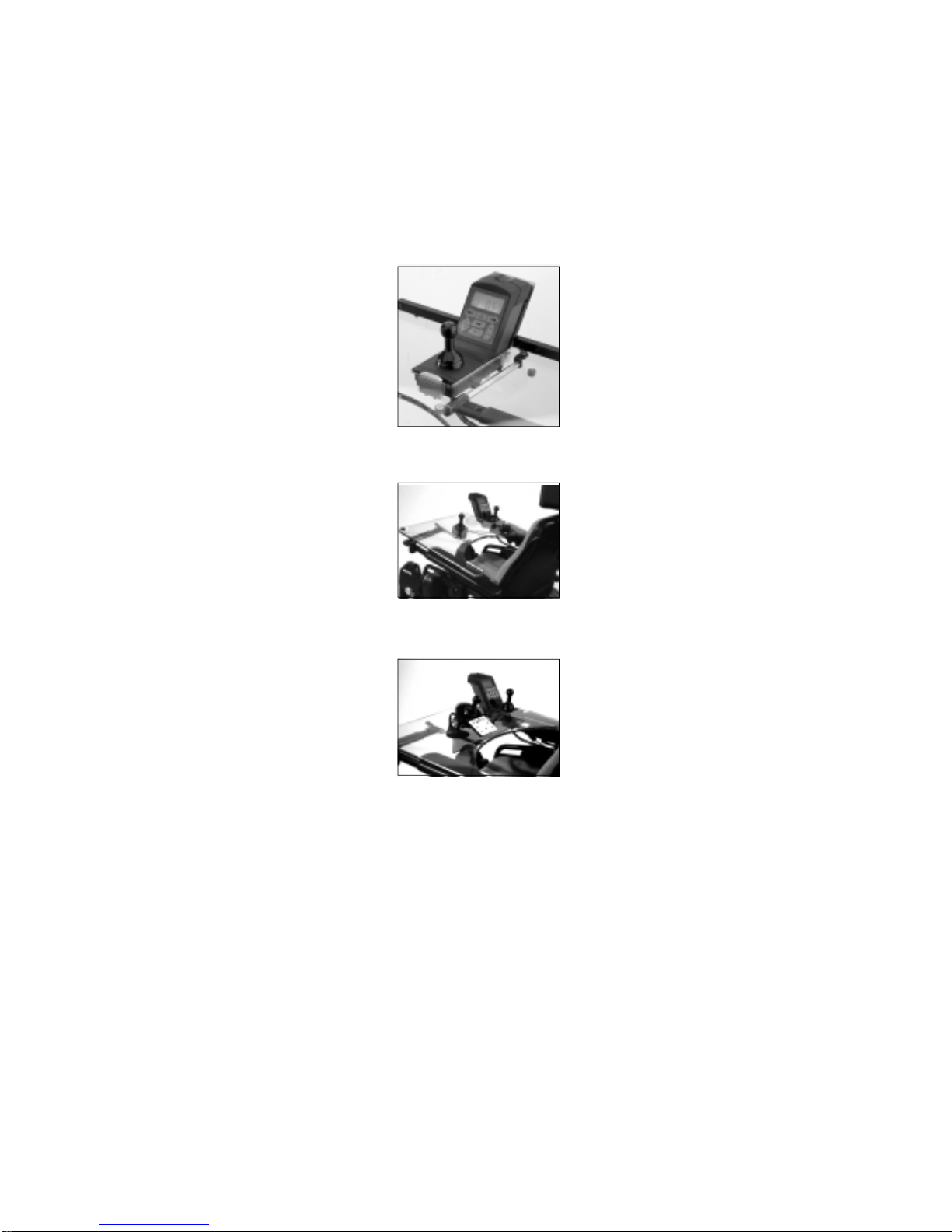
19
TABLE-OPERATED VERSION
Table-operated version, Code
813
Multifunctional table-operated
version,
Code544
Table-operated version, Code
548
MEYRA offers three standard table-operated versions:
Deviations from the standard version can take consideration of individual requirements within the fra-
mework of custom-made solutions. (lease refer to Special table-operated version)
Benefits:
– Operating device can be
folded up, table surface is
clear
– Keypad within reach of
control hand
– Display in the centre
Benefits:
– Joystick can be positioned
where required
– Removable operating lever,
table surface is clear
– Flexible joystick available for
spastic users, no danger of
injury
Benefits:
– Joystick and keypad form a
single unit
– Can be positioned as requi-
red thanks to suction attach-
ment, variable position
– Easily removed; level, washa-
ble work surface

20
a
Stay bar (20 mm) with armrest for Sprint, Sprint
Recaro and Optimus Recaro models Stay bar (14 mm) with armrest for Sprinti, Euro-
Sprint, Optimus and Optimus models Light
b
a
All table-operated versions comprise a polycarbonate table which
can be folded away and swivelled downwards when getting into or
out of the wheelchair.
All table-operated versions are slid from the front into the top of
the armrest using the table stay bar and secured by a turning knob
(a).
The table stay bar and top section of the armrest depend on the type of wheelchair concerned; when
retrofitting, always supply exact information as regards the wheelchair type and equipment in order to
avoid incorrect deliveries.
All table-operated versions can be adjusted in length and the seat
can also be adjusted in width.
Length setting: a=16cm
Width setting: b=9cm
If in exceptional cases the setting measurements are insufficient,
the plastic plate can be adapted by specialist dealers or MEYRA.
TABLE-OPERATED VERSION
This manual suits for next models
3
Table of contents
Other Meyra Wheelchair manuals

Meyra
Meyra 2.432 User manual

Meyra
Meyra MEX-X 1.130 User manual

Meyra
Meyra Ortopedia iTravel 1.054 User manual

Meyra
Meyra 1.7 series User manual

Meyra
Meyra 2.445 User manual

Meyra
Meyra 2.845 User manual

Meyra
Meyra 1.611 User manual

Meyra
Meyra ORTOPEDIA Solero Light 9.072 User manual

Meyra
Meyra 1.610 Manual

Meyra
Meyra 2.360 User manual

Meyra
Meyra MOTIVO 2.250 User manual

Meyra
Meyra 1.620 User manual

Meyra
Meyra Optimus User manual

Meyra
Meyra 1.620 User manual

Meyra
Meyra 1.155 User manual

Meyra
Meyra 9.050 User manual

Meyra
Meyra EUROCHAIR 2 THE ORIGINAL 2.750 User manual

Meyra
Meyra SPRINT GT 2.593 User manual

Meyra
Meyra Optimus 2 User manual

Meyra
Meyra 1.610 User manual


