Mhouse MhouseKit PF Product manual
MhouseKit PF
EN Installation instructions and
warnings
IT Istruzioni ed avvertenze
per l’installazione
FR Instructions et avertisse-
ments pour l’installation
ES Instrucciones y advertencias
para la instalación
DE Anweisungen und Hinweise
für die Installation
PL Instrukcje i zalecenia doty-
czące instalacji
NL Aanwijzingen en aanbevelin-
gen voor de installatie
Codice: IST279.4862 - Rev. 00 del 06 - 04 - 2009
Free
Energy

1– English
English
GENERAL SAFETY WARNINGS AND PRECAUTIONS
The design and manufacture of the devices making up the prod-
uct and the information in this manual fully comply with current
standards governing safety. However, incorrect installation or
programming may cause serious physical injury to those work-
ing on or using the system. For this reason, during installation,
always strictly observe all instructions in this manual.
If in any doubt regarding installation, do not proceed and contact the
Mhouse Technical Assistance for clarifications.
WORKING IN SAFETY!
Warning – for personal safety it is important to observe
these instructions.
Warning – Important instructions for safety - therefore
keep these instructions in a safe place to enable future
product maintenance and disposal procedures.
Observe the following warnings:
– make electrical connections exclusively as envisaged in this
manual incorrect: connections could cause serious damage to
the system.
– The cables supplied must be used indoor and in protected
environments. For use outdoors, the cables must be protected
with adequate ducting.
– never touch the battery connector contacts with metal objects.
Considering the risk situations that may arise during installation
phases and use of the product, the devices supplied in the pack
must be installed in observance of the following warnings:
– never make any modifications to part of the devices other than
those specified in this manual. Operations other than as specified
can cause malfunctions. The manufacturer declines all liability for
damage caused by makeshift modifications to the product.
– never place devices near to sources of heat and never expose to
naked flames. This may damage system components and cause
malfunctions, fire or hazardous situations.
– ensure that the devices cannot come into contact with water or
other liquids. During installation ensure that no liquids penetrate the
devices present.
– the product packaging material must be disposed of in full obser-
vance of current local legislation governing waste disposal.
KNOWLEDGE OF THE PRODUCT AND PREPARATION FOR INSTALLATION
CHAPTER 1 – DESCRIPTION AND INTENDED USE
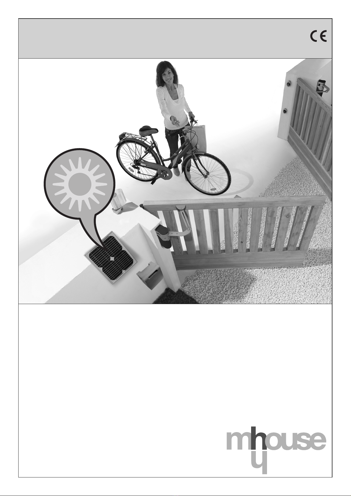
PF is a solar power system designed for use with Mhouse automa-
tions for gates, garage doors, sun awnings and similar products
(fig. 1).
Any other use is to be considered improper! The manufacturer
declines all liability for damage resulting from improper use of
the product and other than as specified in this manual.
This system uses exclusively solar power to run an automation, with-
out the use of electrical mains power.
It can supply electrical energy continuously and permanently and
can be used anywhere (for example to automate a gate situated far
from the electrical mains).
The system comprises a photovoltaic panel and an electric battery:
– the photovoltaic panel is a device able to convert solar energy
directly into electrical energy.
– the battery is a device that stores the electrical power produced
by the photovoltaic panel during the hours of sunlight, making it
available at any time of the day, including days with bad weather. A
Led on the front section and an internal buzzer indicate the various
charge/discharge conditions of the internal battery.
The rear of the battery is fitted with 4 holes for wall-mounting. The
battery can be fixed permanently or suspended on hooks to enable
future removal and transport. To facilitate transport, a handle is fitted
and two separable connectors to enable quick detachment of the
panel and automation.
CHAPTER 2 – COMPONENTS TO SET UP A COMPLETE
POWER SUPPLY SYSTEM
Fig. 2 illustrates all components used to set up a complete power
supply system. The components are:
a) Photovoltaic panel mod. PC;
b) Bracket for fixture of the photovoltaic panel;
c) Metal hardware (screws, washers, etc.);
d) Electric battery (mod. PB);
e) Power cable for connection between the battery and automation;
f) “L” type connectors;
g) Screws for “L” type socket fixture.
• Optional Accessories (not supplied in pack)
PF enables complete autonomy of system power, provided that it is
used within the limits as specified in chapter 3.
If these limits are exceeded, for example due to intensive use of the
automation, the energy reserve may not be sufficient.
In these cases a power supply unit is available, (model PBC), for pro-
visional connection to the electrical mains and rapid recharging of
the battery.
CHAPTER 3 – PRELIMINARY INSTALLATION CHECKS AND
PRODUCT APPLICATION LIMITS
To establish suitability of PF with respect to the automation to be
powered, the checks described in this chapter must be performed.
Also check in the chapter “Product technical specifications” that the
technical data of PF are suitable for the envisaged use and refer to
the automation instruction manual (or addendums) to ensure that
operation of the automation is envisaged with PF. Caution! - Simple
presence of a connector for battery power supply does not imply
compatibility. Products compatible with PF have been explicitly
designed to reduce power consumption to a minimum when the au-
tomation is stationary, whereas a product that has not been opti-
mised for such applications, may feature low consumption but risks
excessive consumption, also when stationary, of the energy generat-
ed by the PF panel.
In the vicinity of the automation to be powered, locate the ideal point
for installation of the photovoltaic panel and the battery, taking into
consideration the following restraints.
a) the application limits specified in this chapter;
b) the length of the power cable (3 m) and the cable of the photo-
voltaic panel (3 m);
c) the space available in the vicinity of the automation to be powered.
Also check the following:
d) ensure that the selected surfaces for fixing the two devices are
solid and guarantee a stable fixture.
e) ensure that each device to be installed is in a sheltered location
and protected against the risk of accidental impact.
f) in particular, for each device ensure the following:

English – 2
English
Photovoltaic panel
Ensure that the selected panel installation site guarantees 100%
direct exposure to direct sunlight (full sun) every day of the year. In
particular, ensure that the panel installation site is far from vegeta-
tion, walls or other situations that may create shade on the panel.
Caution! – the sensitive surface must be exposed to direct
sunlight in all points; partial shade, even if small in size (for
example caused by a leaf or other object) will significantly re-
duce the power capacity of the panel.
Also, after installation, check the possibility of correctly position-
ing and inclining the panel, with reference to the instructions in
chapter 5.
Battery
To ensure optimal efficiency of the battery and prolonged lifetime,
it should be installed in a location protected against high summer
temperatures and low winter temperatures.
In fact the battery charge performance depends on the ambient
temperature where the battery is installed; optimal efficiency is
ensured at around 20°C while this is reduced at temperatures be-
low zero.
On the other hand, battery lifetime is influenced above all by high
summer temperatures (above 40°C), which accelerate part age-
ing. Normally the average lifetime is approx. 4-5 years; this also
depends on the intensity of automation use. The ideal situation is
to avoid excessive discharging of the battery due to very frequent
and repetitive manoeuvre cycles over periods of time.
• Application limits: Maximum possible number of cycles
per day within a set period of the year
PF enables complete autonomy of the system it powers, while the
average energy produced by the photovoltaic panel (which in turn is
proportional to that supplied by the sun) remains above that con-
sumed by the automation.
A simple calculation enables an estimate of the maximum number of
cycles per day performed by the automation in a certain period of
the year, provided that a positive energy balance is maintained.
The first part of the calculation (energy available) is dealt with in this
chapter, the second part of the calculation (energy consumed, i.e.
the maximum number of cycles per day) is dealt with in the respec-
tive chapter in the automation instruction manual.
Caution! - Not all automations produced by Mhouse are compatible
with PF. If the automation instruction manual (or addendums) does
not contain the chapter with the calculation of the maximum number
of cycles obtainable with energy supplied by PF, this means that the
automation is not compatible.
Calculating the energy available in a set period of the year
To calculate the energy available in a set period of the year, proceed
as follows (the calculation already takes into account the efficiency of
the photovoltaic panel and battery performance):
01. Fig. 19 shows the average quantity of solar power radiated by
the sun to the earth within one year. The 7 outlined areas show
that the quantity of energy differs from zone to zone, due to a
number of factors such as latitude, presence of clouds etc.
–– Therefore, in fig. 19 read value “Ea” of the average annual
energy, available in your geographical area, as well as the de-
grees of latitude of your geographical location.
02. As well as the measured value “Ea”, the variable progress of
energy available in the various periods of the year must be tak-
en into account with reference to the specific zone. In fact, the
quantity of energy varies (increases/decreases) according to
the seasons (see the curves in graphs AA and BB): in the mo-
nths with more exposure to sunlight (summer) much more ener-
gy is available with respect to winter months; this difference is
less evident in the zones closer to the equator and more accen-
tuated in the zones closer to the terrestrial poles.
–– Therefore, to calculate the lowest number of manoeuvre
cycles per day, refer to graph AA (for zones north of the equa-
tor) or graph BB (for zones south of the equator) and select the
curve related to your latitude and the period of the year with
least exposure to sunlight (corresponding to the lowest point of
the curve). Then cross reference the two values, as shown in
the example on the graph, to obtain the value “Am” (radiation
within a set period).
03. Then calculate the value “Ed”, i.e. the energy available in your
zone within the set period of the year, multiplying the values as
follows: Ea x Am = Ed.
04. Lastly, to calculate the maximum possible number of cycles
per day, for the selected period, calculate using the value
“Ed” obtained (energy available) according to the instructions in
the specific chapter of the automation instruction manual.
Warning – During the day, if the photovoltaic panel remains in the
shade for a certain period of time (in particular from 10 am to 2 pm)
the energy available decreases in proportion to the hours without
panel exposure to sunlight.
CHAPTER 4 – BATTERY DISCHARGE
The previous chapter describes how to calculate the maximum num-
ber of automation cycles per day. This is an estimate based on the
average energy available within the period of one year. In the event of
long periods of particularly adverse weather conditions or when
more manoeuvres are required than those usually admitted, the
stored energy may run out.
When this occurs, the led on the battery indicates the battery dis-
charged status with one flash at regular intervals (approx. 5 seconds)
and beeps emitted in time with the Led: this signal may be temporary
or permanent. In both cases, the battery must be recharged accord-
ing to one of the following procedures:
A) rapid recharge of battery using power supply unit mod. PBC
(optional accessory);
B) limit use of the automation until the weather conditions improve
and enable recharging of the battery via the photovoltaic panel. In
both cases, the “battery discharged” warning is cleared when the
system reaches sufficient electrical autonomy to enable automation
operation.

3– English
English
COMPONENT ASSEMBLY AND CONNECTIONS
CHAPTER 5
STEP 1 – Assembly of photovoltaic panel support bracket
Assemble all components of the support bracket on the rear of the
panel, as shown in fig. 3.
Caution! – The bracket at the rear of the panel must be positioned
(fig. 3-b) according to the type of position in which the panel is
mounted. To select the position, refer to fig. 6.
STEP 2 – Photovoltaic panel positioning
Caution! – For optimal operation of the panel, it must be posi-
tioned precisely in the selected location. Therefore, after perform-
ing the checks as described in chapter 3, strictly observe the follow-
ing instructions: as a general rule, the panel must be positioned so
that it can receive the maximum possible sunlight during the day and
throughout the year. This means that its horizontal position and verti-
cal angle must be calculated on the basis of the location where it is
to be installed.
• Ensure the correct position of the panel on the horizontal
plane as follows:
a) In the installation site, determine the cardinal points NORTH and
SOUTH, with the aid of a compass or a geographical map of the
location.
b) Then position the panel in the direction NORTH or SOUTH,
according to the following:
– if the installation site is in a country North of the equator (Unit-
ed States; Europe; Russia; etc.) the panel must be positioned
exactly SOUTH;
– if the installation site is in a country South of the equator (Latin
America; Australia; Indonesia, etc.) the panel must be positioned
exactly NORTH.
For further information, refer to fig. 4.
• Ensure the correct position of the panel on the vertical plane
as follows:
Considering that it is preferable to ensure maximum efficiency of the
panel during the winter period, when there is less energy available
than in the summer, the panel should be positioned at an angle that
ensures reception of the sun rays perpendicular (from front) to the
sensitive surface.
This angle corresponds to the latitude of the location and can be
read on any commercial geographical map. For example, Madrid
has a latitude of 40°; Venice 45°; or London approx 50° etc. For fur-
ther information, refer to fig. 5.
STEP 3 – Fixing the photovoltaic panel in the selected site
After establishing the precise position of the panel, fix to the selected
surface as shown in fig. 6.
STEP 4 – Fixing the battery in the selected site
After performing the checks as described in chapter 3 and establish-
ing the precise position of the battery, fix to the selected surface as
shown in fig. 13. Note – use the 2 lower screws only if you wish to
anchor the battery in a permanent position, i.e. when removal is not
required.
STEP 5 – Cable routing
After fixing the panel and battery, route the panel cable through the
tube or protection ducting through to the battery.
With reference to the instruction manual of the automation to be
powered, remove the control unit protection cover. Then pass the
end of the power cable (with wires exposed) through the automation
IMPORTANT! – The cables supplied must be used in
indoor and protected environments. For use outdoors, the
cables must be protected with adequate ducting.
(where the other cables are routed). Then route the cable through the
protection ducting (if present) through to the battery.
Caution! – Do not connect the power cable to the control unit; leave
access to the control unit open.
STEP 6 – Assembly of “L” socket on the photovoltaic panel
cable
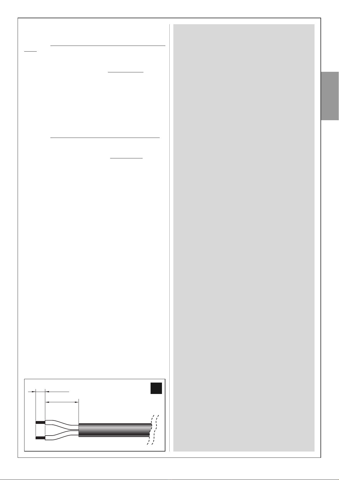
If the cable is too long, it can be shortened, taking care to strip the
wires so that their length is equal to the values specified in the fig. 20
(caution! – different lengths may impair subsequent assembly of the
socket).
Then proceed with assembly of the GREY “L” type socket on the
end of the panel cable, as follows:
01. Insert the various elements of the socket on the cable, taking
care to observe the sequence as shown in fig. 7;
CAUTION! – Do not modify the electric jumper on the connec-
tor (fig. 8).
02. Using a slotted screwdriver, attach the blue wire to terminal n°
1on the connector and the brown wire to the earthing termi-
nal (4) (fig. 9):
Note – The reference numbers and symbols are printed on the
connector below the terminals and on the opposite side.
03. After fixing the two wires, insert the connector in its casing
(fig. 10).
Important – The correct position of the connector is that
with the earthing symbol in the lower position (see fig. 10);
04. Then pull the cable outwards from the socket and insert the
seal and washer (fig. 11-a-b). Lastly, tighten the cable clamp
(fig. 11-c) using a wrench, to guarantee completely sealed clo-
sure.
05. After assembling the socket, position the seal supplied on the
connection side (fig. 12).
STEP 7 – Assembly of “L” socket on the power cable
If the cable is too long, it can be shortened, taking care to strip the
wires so that their length is equal to the values specified in the fig. 20
(Caution! – different lengths may impair subsequent assembly of the
socket).
Then proceed with assembly of the BLACK “L” type socket on the
end of the power cable, as follows:
01. Insert the various elements of the socket on the cable, taking
care to observe the sequence as shown in fig. 7;
CAUTION! – Do not modify the electric jumper on the connec-
tor (fig. 8).
02. Using a slotted screwdriver, attach the blue wire to terminal n°
1on the connector and the brown wire to the earthing termi-
nal (4) (fig. 9):
Note – The reference numbers and symbols are printed on the
connector below the terminals and on the opposite side.
03. After fixing the two wires, insert the connector in its casing
(fig. 10).
Important – The correct position of the connector is that
with the earthing symbol in the lower position (see fig. 10);
04. Then pull the cable outwards from the socket and insert the
seal and washer (fig. 11-a-b). Lastly, tighten the cable clamp
(fig. 11-c) using a wrench, to guarantee a completely sealed
closure.
05. After assembling the socket, position the seal supplied on the
connection side (fig. 12).
STEP 8 – Connecting the photovoltaic panel to the battery
To connect the panel to the battery, proceed as follows:
01. Connect the GREY “L” type socket to the “IN” connector on
the battery (fig.14);
02. To select the most suitable connection configuration for the

English – 4
English
connection of all system devices, refer to the example shown in
fig. 15. Note – If frequent disconnection of the battery plug is
envisaged, use the screw in fig. 16-a. Otherwise use the screw
in fig. 16-b.
Caution! - When the battery is recharging via the photovoltaic panel,
the red led emits 2 short flashes every 5 seconds. Therefore check
that this signal is present when the panel is exposed to the sunlight.
STEP 9 – Connecting the battery to the automation
To connect the battery to the automation, proceed as follows:
01. Connect the BLACK “L” type socket to the “OUT” connector
on the battery (fig. 17);
02. To select the most suitable connection configuration for the
connection of all system devices, refer to the example shown in
fig. 18. Note – If frequent disconnection of the battery plug is
envisaged, use the screw in fig. 16-a. Otherwise use the screw
in fig. 16-b.
03. Access the control unit of the automation and insert the power
cable connector in the buffer battery socket on the control unit.
To locate this socket, refer to the instruction manual of the
automation to be powered.
Caution! - when the automation is powered by PF, it must NEV-
ER BE POWERED via the mains at the same time.
––– General note –––
IMPORTANT – After connecting the product to the automation,
the system may not be operative immediately; this depends on
the fact that the battery may be discharged due to the natural
process of discharging over time, even when stored. In this case,
there are two ways to proceed:
A) Disconnect the battery from the automation control unit and
wait for a few days for the photovoltaic panel to receive sufficient
sunlight in order to recharge the battery;
B) Proceed with rapid recharge of battery using back-up power
supply unit mod. PBC (optional accessory).
––– Visual and audible signals –––
The PF is equipped with a led and a buzzer.
• When the battery is recharging (via the photovoltaic panel or
battery charger) the red led emits 2 short flashes every 5 sec-
onds Therefore check that this signal is present, also after instal-
lation, when the panel is exposed to the sunlight.
• When the battery has completed charging via the battery charg-
er, the led remains permanently lit.
• When the battery is discharged, the red led emits one short
flash every 5 seconds, accompanied by a beep.
––– Notes for use –––
• NEVER leave the battery connected to the automation
if the photovoltaic panel is not also connected and
operational.
Caution! - If the battery is not sufficiently recharged, the reserve
will run out within a few days.
•If the automation is not used for prolonged periods, detach
the connectors of the automation and photovoltaic panel
from the battery and store the latter in a cool and dry loca-
tion.
4 mm
10 mm
20
5– English
English
WHAT TO DO IF... (troubleshooting guide)
• The automation control unit does not turn on and the led
remains off.
This may be caused by incorrect connections or electric wires not
fully inserted. Otherwise the battery may be totally discharged, in
which case no signal can be sent: in this case a rapid recharge is
required by means of power supply unit (mod. PBC) or wait for the
photovoltaic panel (connected correctly) to recharge the battery.
• The battery tends to discharge too quickly.
This may depend on excessive ageing of the battery, in which case it
should be replaced; otherwise it may be due to excessively intensive
use of the automation, over the application limits envisaged in this
manual, found in chapter 3.
Otherwise the automation may not be compatible for operation with
PF, or the automation is incorrectly configured for low consumption,
or too many accessories are connected.
• The battery no longer recharges.
This may be due to a malfunction of the photovoltaic panel caused
by incorrect installation, incorrect cable connections, or malfunction
of the battery.
PERIODIC MAINTENANCE OPERATIONS
In general, this product does not require special maintenance; how-
ever, regular checks over time will ensure system efficiency.
Therefore, to ensure correct maintenance, check every 6 months
that the photovoltaic panel has not accumulated dirt (leaves, sand,
etc.) as this may reduce efficiency.
Also check whether battery replacement is required, as the ageing
process reduces autonomy over time.
Take into account that battery lifetime is influenced above all by high
summer temperatures, which accelerate part ageing. Normally the
average lifetime is approx. 4-5 years; this also depends on the inten-
sity of automation use: The ideal situation is to avoid excessive dis-
charging of the battery due to very frequent and repetitive manoeu-
vre cycles over periods of time.
CAUTION – The battery must be replaced exclusively by skilled
and qualified personnel.
DISPOSAL
Product disposal
This product is an integral part of the automation and therefore
must be disposed together with the latter.
As in installation, also at the end of product lifetime, the disassembly
and scrapping operations must be performed by qualified personnel.
This product comprises various types of materials: some may be
recycled others must be disposed of. Seek information on the recy-
cling and disposal systems envisaged by the local regulations in your
area for this product category.
Caution! – some parts of the product may contain pollutant or haz-
ardous substances which, if disposed of into the environment, may
cause serious damage to the environment or physical health.
As indicated by the symbol alongside, disposal of
this product in domestic waste is strictly prohibited.
Separate the waste into categories for disposal,
according to the methods envisaged by current
legislation in your area, or return the product to the
retailer when purchasing a new version.
The product also contains a lead battery, i.e. an element that is high-
ly pollutant if not disposed of correctly. The battery must be removed
and disposed of as specified in the paragraph “Battery disposal”.
Caution! – Local legislation may envisage serious fines in the event
of abusive disposal of this product.
Battery disposal
Caution! – The battery contains pollutant substances and therefore
must NEVER be disposed of in common waste collection points
after removal. Dispose of or recycle according to current local stan-
dards.
English – 6
English
TECHNICAL SPECIFICATIONS OF PRODUCT COMPONENTS
WARNINGS: • The product PF is produced by Nice S.p.a. (TV) I. Mhouse is a commercial trademark owned by Nice S.p.a. • All technical specifications stated
herein refer to an ambient temperature of 20°C (± 5°C) • Nice S.p.a. reserves the right to apply modifications to the product at any time as deemed necessary,
while maintaining the same functionalities and intended use • The estimated minimum number of manoeuvres per day, is applicable exclusively with the photo-
voltaic panel positioned correctly and in the conditions as specified in chapter 3 under the heading “Application Limits”.
PB BATTERY
DESCRIPTION DATA
Rated voltage: 24 V
Maximum current: 10 A
Rated battery capacity: 20 Ah
Protection rating: IP 44
Operation temperature: from -20°C to +50°C (when charging using the back-up power supply unit: from 0°C to +40°C)
Complete recharging time: approx. 15 hours (when using the back-up power supply unit)
Dimensions: 258 mm x 235 mm x 180 mm
Weight: 14 kg
Note – The batteries used on PB are type VRLA, “Valve Regulated Lead Acid Batteries”, i.e. sealed and valve-controlled, compliant with the specific
provision A67 of the IATA/ICAAO Regulation governing hazardous products. PB and PF are therefore not considered hazardous goods and may be
transported without any risk by air, sea and on road.
PC PHOTOVOLTAIC PANEL
DESCRIPTION DATA
Rated voltage: 24 V
Maximum power: 10 W
Operation temperature: from -40°C to +85°C
Dimensions: 354 mm x 290 mm x 28 mm
Weight: 1,4 Kg
Warning – The glass of the photovoltaic panel has been tested to resist to hailstones and medium entity impact (resistant to impact with a steel
sphere of 227 g, falling from a height of 1 metre). In the event of particularly consistent hail or impact, the glass may be damaged; in this case con-
tact the Mhouse Technical Assistance service.
CE DECLARATION OF CONFORMITY
Note - The contents of this declaration correspond to those of the last revision available of the official document, deposited at the registered offices of Nice
S.p.a., before printing of this manual. The text herein has been re-edited for editorial purposes.
PF is produced by Nice S.p.a. (TV) I; Mhouse is a commercial trademark owned by Nice S.p.a.
Number: 304/PF Revision: 0
The undersigned Luigi Paro, in the role of Managing Director, declares under his sole responsibility, that the product:
Manufacturer’s Name: NICE s.p.a.
Address: Via Pezza Alta 13, Z.I. Rustignè, 31046 Oderzo (TV) Italy
Type: Mhouse solar power kit
Models: PF
Accessories: PBC
conform with the requirements of the following EC directives:
• 2006/95/EEC (ex-directive 73/23/EC) DIRECTIVE 2006/95/EC OF THE EUROPEAN PARLIAMENT AND OF THE COUNCIL of
12 December 2006 concerning standardization of member states on electrical material to be used within certain voltage limits,
in accordance with the following harmonized standard:
EN 60335-1:2002 + A1:2004 + A11:2004 + A12:2006 + A2:2006
• 2004/108/EEC (ex-directive 89/336/EEC) DIRECTIVE 2004/108/EC OF THE EUROPEAN PARLIAMENT AND OF THE COUN-
CIL of 15 December 2004 concerning standardization of the legislation of member states on electromagnetic compatibility and
which repeals 89/336/EEC, in accordance with the following standards:
EN 61000-6-2:2005; EN 61000-6-3:2007
Oderzo, 11.03.2009
Luigi Paro (Managing Director)

1– Italiano
Italiano
AVVERTENZE E PRECAUZIONI GENERALI PER LA SICUREZZA
La progettazione, la fabbricazione dei dispositivi che compon-
gono il prodotto e le informazioni contenute nel presente
manuale rispettano pienamente le normative vigenti sulla sicu-
rezza. Ciò nonostante, un’installazione errata può causare gravi
ferite alle persone che eseguono il lavoro e a quelle che useran-
no l’impianto. Per questo motivo, durante l’installazione, è
importante seguire attentamente tutte le istruzioni riportate in
questo manuale.
Non procedere con l’installazione se si hanno dubbi di qualunque
natura e richiedere eventuali chiarimenti al Servizio Assistenza
Mhouse.
OPERARE IN CONDIZIONI DI SICUREZZA!
Attenzione – Per la sicurezza delle persone è importante
rispettare queste istruzioni.
Attenzione – Istruzioni importanti per la sicurezza, quindi,
conservare queste istruzioni per facilitare eventuali interventi
futuri di manutenzione o di smaltimento del prodotto.
Rispettare le seguenti avvertenze:
– effettuare esclusivamente i collegamenti elettrici previsti nel
presente manuale: un’errata esecuzione dei collegamenti
potrebbe causare gravi danni al sistema.
– I cavi in dotazione devono essere utilizzati in ambienti interni e
protetti. Per poterli utilizzare all’esterno è necessario protegge-
re i cavi con adeguati condotti di protezione.
– non toccare con oggetti metallici i contatti dei connettori pre-
senti sull’accumulatore.
Considerando le situazioni di rischio che possono verificarsi
durante le fasi d’installazione e di uso del prodotto è necessario
installare i dispositivi presenti nella confezione osservando le
seguenti avvertenze:
– non eseguire modifiche su nessuna parte dei dispositivi, se non
quelle previste nel presente manuale. Operazioni non permesse pos-
sono solo causare malfunzionamenti. Il costruttore declina ogni
responsabilità per danni derivanti da prodotti modificati arbitraria-
mente.
– non mettere i dispositivi vicino a fonti di calore né esporli a fiamme
libere. Tali azioni possono danneggiarli ed essere causa di malfunzio-
namenti, incendio o situazioni di pericolo.
– evitare che i dispositivi possano venire immersi in acqua o in altre
sostanze liquide. Durante l'installazione evitare che dei liquidi possa-
no penetrare all'interno dei dispositivi.
– il materiale dell’imballaggio del prodotto deve essere smaltito nel
pieno rispetto della normativa presente a livello locale.
CONOSCENZA DEL PRODOTTO E PREPARAZIONE ALL’INSTALLAZIONE
CAPITOLO 1 – DESCRIZIONE E DESTINAZIONE D’USO
PF è un sistema di alimentazione a energia solare destinato agli
automatismi Mhouse per cancelli, portoni da garage, tende da sole e
prodotti similari (fig. 1).
Ogni altro uso è da considerarsi improprio! Il costruttore non
risponde dei danni risultanti da un uso improprio del prodotto,
diverso da quanto previsto nel presente manuale.
Questo sistema sfrutta esclusivamente l’energia solare per alimentare
un’automazione, senza l’ausilio del collegamento alla rete elettrica.
È in grado di erogare energia elettrica in modo continuo e permanen-
te e può essere utilizzato ovunque (ad esempio, per automatizzare
un cancello collocato lontano dalla rete elettrica).
Il sistema è composto da un pannello fotovoltaico e da un accumu-
latore di energia elettrica:
– il pannello fotovoltaico è un dispositivo in grado di convertire
l’energia solare direttamente in energia elettrica.
– l’accumulatore è un dispositivo che immagazina l’energia elettrica
prodotta dal pannello fotovoltaico durante le ore di sole e la rende
disponibile in ogni ora del giorno, compresi i giorni con cattivo tem-
po. Un Led sulla parte frontale ed un buzzer interno segnalano i vari
stati di carica o scarica della batteria interna.
Sul retro dell’accumulatore sono presenti 4 fori per il fissaggio a
parete. È possibile ottenere un fissaggio fisso e permanente oppure
un fissaggio con ganci che permettono la rimozione ed il trasporto
dell'accumulatore. Per facilitare quest’ultima operazione è presente
una maniglia e due connettori separabili, per poter scollegare veloce-
mente il pannello e l’automatismo.
CAPITOLO 2 – COMPONENTI PER REALIZZARE UN SISTE-
MA DI ALIMENTAZIONE COMPLETO
La fig. 2 mostra tutti i componenti necessari per poter realizzare un
sistema di alimentazione completo. I componenti sono:
a) Pannello fotovoltaico mod. PC;
b) Staffa per il fissaggio del pannello fotovoltaico;
c) Minuteria metallica (viti, rondelle, ecc.);
d) Accumulatore di energia elettrica mod. PB;
e) Cavo di alimentazione per il collegamento tra l’accumulatore e
un’automatismo;
f) Connettori “a pipetta”;
g) Viti per il fissaggio della presa “a pipetta”.
• Accessori opzionali (non presenti nella confezione)
PF consente la completa autonomia energetica dell’impianto, solo se
viene utilizzato nel rispetto dei limiti riportati nel capitolo 3.
Se questi limiti vengono superati, – ad esempio a causa di un uso in-
tensivo dell’automazione, – può verificarsi l'esaurimento dell’energia
accumulata.
Per questi casi è disponibile un alimentatore, modello PBC, da colle-
gare provvisoriamente alla rete elettrica per ricaricare velocemente
l’accumulatore.
CAPITOLO 3 – VERIFICHE PRELIMINARI ALL’INSTALLA-
ZIONE E LIMITI D’IMPIEGO DEL PRODOTTO
Per stabilire l’idoneità di PF rispetto all’automatismo da alimentare
occorre effettuare le verifiche descritte in questo capitolo.
Inoltre, controllare nel capitolo “Caratteristiche tecniche del prodot-
to” se i dati tecnici di PF sono appropriati per l'utilizzo previsto e veri-
ficare nel manuale di istruzioni (o negli addendum) dell'automatismo
se il funzionamento di quest’ultimo è previsto con PF. Attenzione! -
La sola presenza di un connettore per l’alimentazione a batterie non
è indice di compatibilità. I prodotti compatibili con PF sono stati
espressamente progettati per ridurre all'essenziale il consumo ener-
getico quando l’automatismo è fermo, mentre un prodotto non otti-
mizzato, pur consumando poco, rischia di consumare, anche da fer-
mo, gran parte dell'energia prodotta dal pannello del PF.
Individuare vicino l’automatismo da alimentare, il punto più adatto
per installare il pannello fotovoltaico e l’accumulatore, tenendo in
considerazione i seguenti vincoli:
a) i limiti d’impiego descritti in questo capitolo;
b) la lunghezza del cavo di alimentazione (3 m) e di quello del pannel-
lo fotovoltaico (3 m);
c) lo spazio disponibile in prossimità dell’automatismo da alimentare.
Inoltre, effettuare le seguenti verifiche:
d) verificare che le superfici scelte per fissare i due dispositivi siano
solide e possano garantire un fissaggio stabile.
e) verificare che ciascun dispositivo da installare sia collocato in una

Italiano – 2
Italiano
posizione protetta da urti accidentali.
f) in particolare, per ciascun dispositivo, verificare quanto segue:
Pannello fotovoltaico
Accertarsi che il luogo prescelto per l’installazione del pannello
possa garantire il 100% dell’insolazione diretta (sole pieno), in
qualsiasi giornata dell’anno. In particolare, installare il pannello lon-
tano da vegetazione, muri o altre situazioni che possano creare
zone d’ombra sulla sua superficie. Attenzione! – la superficie
sensibile deve essere irradiata dai raggi solari in ogni punto e
in modo diretto; un’ombra parziale, anche se di piccole
dimensioni (ad esempio, dovuta, a una foglia o ad altro), ridu-
ce la capacità energetica del pannello.
Inoltre accertarsi che dopo la sua installazione ci sia la possibilità
di orientare e inclinare correttamente il pannello, secondo le
istruzioni riportate nel capitolo 5.
Accumulatore
Per ottenere dall’accumulatore un’efficienza ottimale e una lunga
durata, è preferibile installare quest’ultimo in un punto protetto dal-
le alte temperature estive e dalle basse temperature invernali.
Infatti, il rendimento dell’accumulatore dipende dalla tempera-
tura dell’ambiente in cui questo è installato; l’efficienza è ottimale
intorno ai 20°C mentre si riduce per temperature sotto lo zero.
Invece, la longevità dell’accumulatore è influenzata soprattutto
dalle alte temperature estive (sopra i 40°C) che accellerano l’invec-
chiamento delle parti. Normalmente la vita media è di circa 4-5
anni; questa dipende anche dall’intensità con la quale si usa l’au-
tomazione. L’ideale è non lasciare che l’accumulatore si scarichi
eccessivamente a causa di manovre ravvicinate e prolungate nel
tempo.
• Limiti d’impiego: numero massimo possibile di cicli al
giorno, in un determinato periodo dell’anno
PF consente la completa autonomia energetica dell’impianto che ali-
menta, fino a quando l’energia media prodotta dal pannello fotovol-
taico (che a sua volta è proporzionale a quella fornita dal sole) rimane
superiore a quella consumata dall'automatismo.
Con un semplice calcolo è possibile stimare il numero massimo di
cicli al giorno che l’automazione può eseguire in un determinato pe-
riodo dell’anno, affinchè questo bilancio energetico rimanga positivo.
La prima parte del calcolo (l’energia disponibile) è trattata in questo
capitolo; la seconda parte del calcolo (l’energia consumata, cioè il
numero massimo di cicli al giorno) è trattata nel rispettivo capitolo pre-
sente nel manuale dell'automatismo.
Attenzione! - Non tutti gli automatismi prodotti da Mhouse sono com-
patibili con PF. Se nel manuale di istruzioni (o negli addendum) dell’au-
tomatismo non c’è il capitolo per il calcolo dei cicli massimi ottenibili
con l’energia fornita da PF, significa che l'automatismo non è compa-
tibile.
Stabilire l’energia disponibile in un determinato periodo dell’anno
Per stabilire l’energia disponibile in un determinato periodo dell’anno,
procedere nel modo seguente (il calcolo tiene già conto dell’efficienza
del pannello fotovoltaico e del rendimento dell’accumulatore):
01. La fig. 19 mostra la quantità media di energia solare irradiata
dal sole sulla Terra, nell’arco di un anno. Le 7 aree evidenziate
indicano che la quantità di energia risulta diversa da zona a
zona, a causa di alcuni fattori come la latitudine, la presenza o
meno di corpi nuvolosi ecc..
–– Quindi, nella fig. 19 rilevare il valore “Ea” dell’energia media
annua, disponibile nella vostra zona geografica; inoltre rilevare
anche i gradi della latitudine a cui si trova la vostra zona.
02. Oltre al valore “Ea” rilevato, per la vostra zona occorre conside-
rare anche l’andamento variabile dell’energia, nei vari periodi
dell’anno. Infatti, a causa del susseguirsi delle stagioni, la quan-
tità di energia varia in più o in meno (vedere le curve dei grafici
AA e BB): nei mesi con maggior insolazione (quelli estivi) è
disponibile molta più energia che nei mesi invernali; questa dif-
ferenza è meno evidente nelle zone verso l’equatore e più
accentuata nelle zone verso i poli terrestri.
–– Quindi, se si desidera conoscere il numero più basso di cicli
di manovre al giorno, scegliere nel grafico AA (per le zone a
nord dell'equatore) o nel grafico BB (per le zone a sud del-
l’equatore) la curva relativa alla vostra latitudine e il periodo del-
l’anno con l’irraggiamento minore (questo corrisponde al punto
più basso della curva). Infine incrociare i due dati, come nel-
l’esempio all’interno del grafico, per ottenere il valore “Am”
(irraggiamento relativo a un periodo).
03. A questo punto calcolare il valore “Ed”, cioè l’energia disponibi-
le nella vostra zona per quel determinato periodo dell’anno,
moltiplicando i dati come segue: Ea x Am = Ed.
04. Infine, per ottenere il numero massimo possibile di cicli al
giorno, per il periodo scelto, proseguire il calcolo utilizzando il
dato “Ed” trovato (energia disponibile) e le istruzioni riportate
nel capitolo specifico del manuale dell’automatismo.
Avvertenza - Se durante la giornata il pannello fotovoltaico rimane in
ombra per una parte del tempo (in particolare, dalle ore 10.00 alle ore
14.00), l’energia disponibile si riduce in funzione delle ore mancanti di
esposizione del pannello al sole.
CAPITOLO 4 – ESAURIMENTO DELLA CARICA ELETRICA
DELL’ACCUMULATORE
Nel capitolo precedente è stato descritto come calcolare il numero
massimo possibile di cicli al giorno dell'automazione. Si tratta di una
stima sulla base dell'energia mediamente disponibile lungo l'arco
dell'anno. Se ci fosse un lungo perido di tempo con clima particolar-
mente avverso o se per particolari esigenze ci fosse la necessità di
eseguire più manovre di quelle conentite, potrebbe capitare di esau-
rire l'energia accumulata.
Quando questo accade, il Led sull’accumulatore segnala lo stato di
batteria scarica con 1 lampeggio ciclico del Led (ad intervalli di circa
5 secondi) e con dei “beep” acustici sincronizzati con il Led: questa
segnalazione può essere temporanea o permanente. In ambedue i
casi, occorre ricaricare l’accumulatore procedendo in uno dei se-
guenti modi:
A) effettuare una ricarica veloce dell’accumulatore utilizzando l’ali-
mentatore mod. PBC, accessorio opzionale;
B) limitare l’uso dell’automazione in attesa che migliorino le condizio-
ni climatiche e permettano così la ricarica dell’accumulatore attraver-
so il pannello fotovoltaico. In ambedue le circostanze, l’avviso di
“batteria scarica” termina quando il sistema raggiunge una sufficien-
te autonomia elettrica per far funzionare l’automazione.
3– Italiano
Italiano
ASSEMBLAGGIO E COLLEGAMENTO DEI VARI COMPONENTI
CAPITOLO 5
PASSO 1 – Assemblaggio della staffa di supporto del pannello
fotovoltaico
Assemblare tutti i componenti della staffa di supporto sul retro del
pannello, procedendo come mostrato in fig. 3.
Attenzione! – La staffa dietro al pannello deve essere posizionata
(fig. 3-b) in funzione del tipo di posizione in cui verrà fissato il pannel-
lo. Per scegliere questa posizione vedere la fig. 6.
PASSO 2 – Posizionamento del pannello fotovoltaico
Attenzione! – Per il buon funzionamento del pannello è ne-
cessario che questo venga posizionato con molta precisione
nel punto prescelto. Quindi, dopo aver effettuato le verifiche ripor-
tate nel capitolo 3, seguire scrupolosamente le seguenti istruzioni: in
linea di principio, il pannello deve essere posizionato in modo che
possa ricevere il massimo della luce solare nell’arco della giornata e
nell’evolversi dell’anno. Questo significa che il suo orientamento sul
piano orizzontale e l’inclinazione sul piano verticale devono essere
calcolati in funzione del luogo in cui il pannello viene installato.
• Definire il corretto orientamento del pannello sul piano oriz-
zontale, procedendo nel modo seguente:
a) Determinare sul luogo dell’installazione, i punti cardinali del NORD
e del SUD, aiutandosi con una bussola o una cartina geografica del
luogo.
b) Orientare quindi il pannello in direzione NORD o SUD, in base alle
seguenti considerazioni:
– se il luogo dell’installazione si trova in un Paese a Nord del-
l’equatore (Stati Uniti; Europa; Russia; ecc.) il pannello deve
essere orientato esattamente in direzione SUD;
– se il luogo dell’installazione si trova in un Paese a Sud del-
l’equatore (America Latina; Australia; Indonesia; ecc.) il pannello
deve essere orientato esattamente in direzione NORD.
Per maggiore chiarezza, fare riferimento alla fig. 4.
• Definire il corretto orientamento del pannello sul piano verti-
cale, procedendo nel modo seguente:
Considerando che è preferibile ottenere la massima efficienza del
pannello nel periodo invernale, quando l’energia disponibile è minore
che nell’estate, occorre orientare il pannello con un’inclinazione tale
da ricevere i raggi del sole perpendicolari (frontali) alla sua superficie
sensibile.
Questa inclinazione corrisponde alla latitudine del luogo e può esse-
re rilevata in qualsiasi cartina geografica: ad esempio, Madrid ha lati-
tudine di 40°; Venezia di 45°; Londra di circa 50° ecc. Per maggiore
chiarezza, fare riferimento alla fig. 5.
PASSO 3 – Fissaggio del pannello fotovoltaico nel punto pre-
scelto
Dopo aver stabilito con esattezza la posizione del pannello, procede-
re a fissarlo sulla superficie prescelta, come mostrato in fig. 6.
PASSO 4 – Fissaggio dell’accumulatore nel punto prescelto
Dopo aver effettuato le verifiche riportate nel capitolo 3 e stabilito
con esattezza la posizione dell’accumulatore, procedere a fissarlo
sulla superficie prescelta, come mostrato in fig. 13. Nota – usare le
2 viti posizionate in basso solo se si desidera ancorare l’accumulato-
re in modo fisso e non asportabile.
PASSO 5 – Passaggio dei cavi
Dopo aver fissato il pannello e l’accumulatore, passare il cavo del
IMPORTANTE! – I cavi in dotazione devono essere utilizza-
ti in ambienti interni e protetti. Per poterli utilizzare all’ester-
no è necessario proteggere i cavi con adeguati condotti di
protezione.
pannello attraverso il tubo o la canalina di protezione, portandolo fino
all’accumulatore.
Facendo riferimento al manuale istruzioni dell’automatismo da ali-
mentare, rimuovere il coperchio di protezione della Centrale di co-
mando. Quindi, passare attraverso l’automatismo (dove passano gli
altri cavi) l’estremità del cavo di alimentazione con i fili spelati, e farlo
uscire dall’automatismo. Infine, passare il cavo attraverso l’eventuale
canalina di protezione portandolo fino all’accumulatore.
Attenzione! – Non collegare il cavo di alimentazione alla Centrale;
lasciare aperto l’accesso alla Centrale.
PASSO 6 – Assemblaggio della presa “a pipetta” sul cavo del
pannello fotovoltaico
Se il cavo è eccessivamente lungo, si può accorciare facendo atten-
zione a spelare i fili in modo che la loro lunghezza risulti uguale a
quelle riportate nella fig. 20 (attenzione! – lunghezze diverse pregiu-
dicano il successivo assemblaggio della presa).
Quindi, procedere ad assemblare la presa “a pipetta” in colore
GRIGIO all’estremità del cavo del pannello, nel modo seguente:
01. Infilare sul cavo i vari elementi che compongono la presa,
rispettando l’ordine mostrato in fig. 7;
ATTENZIONE! – Non modificare il ponticello elettrico presente
sul connettore (fig. 8).
02. Utilizzando un cacciavite a taglio, fissare sul connettore il filo
Blu al morsetto n° 1 e il filo Marrone al morsetto della presa
a terra (4) (fig. 9):
Nota – I numeri e i simboli di riferimento sono stampati sul con-
nettore, in basso rispetto ai morsetti e sulla faccia opposta.
03. Dopo aver fissato i due fili, procedere ad inserire il connettore
nella sua protezione (fig. 10).
Importante – La posizione corretta del connettore è quella
con il simbolo della presa a terra posizionato verso il basso
(vedere la fig. 10);
04. Quindi, tirare il cavo verso l’esterno della presa e inserire in que-
sta la guarnizione e la rondella (fig. 11-a-b). Infine, avvitare il
pressacavo (fig. 11-c) usando una chiave, in modo da ottenere
una chiusura completamente ermetica.
05. Dopo aver assemblato la presa, posizionare sul lato di connes-
sione di quest’ultima la guarnizione in dotazione (fig. 12).
PASSO 7 – Assemblaggio della presa “a pipetta” sul cavo di
alimentazione
Se il cavo è eccessivamente lungo, si può accorciare facendo atten-
zione a spelare i fili in modo che la loro lunghezza risulti uguale a
quelle riportate nella fig. 20 (attenzione! – lunghezze diverse pregiu-
dicano il successivo assemblaggio della presa).
Quindi, procedere ad assemblare la presa “a pipetta” in colore
NERO all’estremità del cavo di alimentazione, nel modo seguente:
01. Infilare sul cavo i vari elementi che compongono la presa,
rispettando l’ordine mostrato in fig. 7;
ATTENZIONE! – Non modificare il ponticello elettrico presente
sul connettore (fig. 8).
02. Utilizzando un cacciavite a taglio, fissare sul connettore il filo
Blu al morsetto n° 1 e il filo Marrone al morsetto della presa
a terra (4) (fig. 9):
Nota – I numeri e i simboli di riferimento sono stampati sul con-
nettore, in basso rispetto ai morsetti e sulla faccia opposta.
03. Dopo aver fissato i due fili, procedere ad inserire il connettore
nella sua protezione (fig. 10).
Importante – La posizione corretta del connettore è quella
con il simbolo della presa a terra posizionato verso il basso
(vedere la fig. 10);
04. Quindi, tirare il cavo verso l’esterno della presa e inserire in que-
sta la guarnizione e la rondella (fig. 11-a-b). Infine, avvitare il
pressacavo (fig. 11-c) usando una chiave, in modo da ottenere
una chiusura completamente ermetica.
Italiano – 4
Italiano
05. Dopo aver assemblato la presa, posizionare sul lato di connes-
sione di quest’ultima la guarnizione in dotazione (fig. 12).
PASSO 8 – Collegamento del pannello fotovoltaico all’accumu-
latore
Per collegare il pannello all’accumulatore, procedere nel modo se-
guente:
01. Connettere la presa “a pipetta” in colore GRIGIO alla presa
“IN” sull’accumulatore (fig. 14);
02. Fissare la presa con la vite di sicurezza in dotazione, facendo
riferimento alla fig. 15. Nota – Se si prevede di scollegare spes-
so la presa dall’accumulatore, utilizzare la vite di fig. 16-a. In
caso contrario, utilizzare la vite di fig. 16-b.
Attenzione! - Quando l’accumulatore si sta ricaricando attraverso il
pannello fotovoltaico, il Led rosso emette 2 brevi lampeggi ogni 5
secondi. Quindi, verificare che questa segnalazione sia presente
quando il pannello è illuminato dal sole.
PASSO 9 – Collegamento dell’accumulatore all’automatismo
Per collegare l’accumulatore all’automatismo, procedere nel modo
seguente:
01. Connettere la presa “a pipetta” in colore NERO alla presa
“OUT” sull’accumulatore (fig. 17);
02. Fissare la presa con la vite di sicurezza in dotazione, facendo
riferimento alla fig. 18. Nota – Se si prevede di scollegare spes-
so la presa dall’accumulatore, utilizzare la vite di fig. 16-a. In
caso contrario, utilizzare la vite di fig. 16-b.
03. Accedere alla Centrale di comando dell’automatismo ed inseri-
re il connettore del cavo di alimentazione nella presa della bat-
teria tampone presente sulla Centrale. Per individuare questa
presa, fare riferimento al manuale istruzioni dell’automatismo da
alimentare.
Attenzione! - quando l’automazione viene alimentata con PF,
questa non può e NON DEVE ESSERE ALIMENTATA contempo-
raneamente anche dalla rete elettrica.
4 mm
10 mm
20
––– Nota generale –––
IMPORTANTE – Dopo aver collegato il prodotto all’automatismo,
l’impianto potrebbe non essere subito operativo; questo dipende
dal fatto che l’accumulatore potrebbe essere scarico a causa del
normale processo di autoscarica che avviene nel tempo, anche
quando il prodotto è a magazzino. In questo caso è possibile pro-
cedere in due modi:
A) Scollegare l’accumulatore dalla Centrale di comando dell’auto-
mazione e attendere qualche giorno affinchè il pannello fotovoltai-
co riceva sufficiente luce solare per ricaricare l’accumulatore;
B) Procedere ad eseguire una ricarica veloce e completa dell’ac-
cumulatore utilizzando l’alimentatore di emergenza mod. PBC
(accessorio opzionale).
––– Segnalazioni luminose e acustiche –––
Il PF dispone di un Led e di un buzzer.
• Quando l’accumulatore è in ricarica (dal pannello fotovoltaico o
dal carica batteria), il Led rosso emette 2 brevi lampeggi ogni 5
secondi. Verificare che questa segnalazione sia presente anche
dopo l’installazione, quando il pannello è illuminato dal sole.
• Quando l’accumulatore ha terminato la ricarica dal carica batte-
ria, il Led rimane acceso fisso.
• Quando l’accumulatore è scarico, il Led rosso emette 1 breve
lampeggio ogni 5 secondi, accompagnato da un beep acustico.
––– Note per l’uso –––
• Non lasciare MAI collegato l’accumulatore all’automa-
tismo se non è anche collegato, e correttamente fun-
zionante, il pannello fotovoltaico.
Attenzione! - Se l’accumulatore non è adeguatamente rica-
ricato, esaurisce la sua riserva entro pochi giorni.
•Se l’automazione non viene usata per lunghi periodi, si
consiglia di scollegare i connettori dell’automatismo e del
pannello fotovoltaico dall’accumulatore e di custodire que-
sto in un luogo fresco e asciutto.

5– Italiano
Italiano
COSA FARE SE... (guida alla risoluzione dei problemi)
• La Centrale di comando dell’automatismo non si accende e il
Led non da nessuna segnalazione.
Questo potrebbe dipendere dai collegamenti non corretti o dai fili
elettrici non perfettamente inseriti. Oppure potrebbe essere l’accu-
mulatore completamente scarico, per cui non in grado di dare alcu-
na segnalazione: in questo caso è necessario operare una ricarica
rapida usando l’alimentatore (mod. PBC) o attendere che il pannello
fotovoltaico, correttamente collegato, cominci a ricaricare l’accumu-
latore.
• L’accumulatore tende a scaricarsi troppo velocemente.
Questo potrebbe dipendere da un invecchiamento eccessivo del-
l’accumulatore per cui sarebbe opportuno sostituire la batteria inter-
na; oppure la causa potrebbe essere un uso troppo intensivo dell’au-
tomazione, oltre i limiti d’impiego previsti in questo manuale, nel ca-
pitolo 3.
Inoltre, potrebbe trattarsi anche di un automatismo non previsto per
l’uso con PF, oppure non correttamente configurato per il basso
consumo o, ancora, con troppi accessori collegati.
• L’accumulatore non si ricarica.
Questo potrebbe dipendere da un malfunzionamento del pannello
fotovoltaico a causa di una sua errata installazione; o da un collega-
mento errato dei cavi; o da un malfunzionamento dell’accumulatore.
INTERVENTI DI MANUTENZIONE PERIODICA
In generale, il presente prodotto non necessita di manutenzioni par-
ticolari; tuttavia, un controllo regolare nel tempo consente di mante-
nere in efficienza l’impianto.
Quindi, per effettuare una manutenzione corretta, verificare ogni 6
mesi che il pannello fotovoltaico non abbia accumulato sporcizia
(foglie, sabbia, ecc.): questa potrebbe diminuire l’efficienza.
Inoltre, è necessario verificare se è il caso di sostituire l’accumulato-
re che, per effetto dell’invecchiamento, potrebbe ridurre nel tempo la
sua autonomia.
Occorre tenere presente che la longevità dell’accumulatore è influen-
zata soprattutto dalle alte temperature estive che accellerano l’invec-
chiamento delle parti. Normalmente la vita media dell’accumulatore
è di circa 4-5 anni; questa dipende anche dall’intensità con la quale
si usa l’automazione: l’ideale è non lasciare che l’accumulatore si
scarichi eccessivamente a causa di cicli di manovre ravvicinati e pro-
lungati nel tempo.
ATTENZIONE – L’eventuale sostituzione dell’accumulatore
deve essere eseguita esclusivamente da personale qualificato
ed esperto.
SMALTIMENTO
Smaltimento del prodotto
Questo prodotto è parte integrante dell'automazione, e dunque,
deve essere smaltito insieme con essa.
Come per le operazioni d'installazione, anche al termine della vita di
questo prodotto, le operazioni di smantellamento devono essere
eseguite da personale qualificato.
Questo prodotto è costituito da vari tipi di materiali: alcuni possono
essere riciclati, altri devono essere smaltiti. Informatevi sui sistemi di
riciclaggio o smaltimento previsti dai regolamenti vigenti sul vostro
territorio, per questa categoria di prodotto.
Attenzione! – alcune parti del prodotto possono contenere sostanze
inquinanti o pericolose che, se disperse nell’ambiente, potrebbero
provocare effetti dannosi sull'ambiente stesso e sulla salute umana.
Come indicato dal simbolo a lato, è vietato gettare
questo prodotto nei rifiuti domestici. Eseguire quin-
di la “raccolta separata” per lo smaltimento, secon-
do i metodi previsti dai regolamenti vigenti sul
vostro territorio, oppure riconsegnare il prodotto al
venditore nel momento dell'acquisto di un nuovo
prodotto equivalente.
Inoltre, il prodotto contiene un accumulatore al piombo, cioè un ele-
mento estremamente inquinante se non smaltito opportunamente.
L'accumulatore deve essere rimosso e smaltito come spiegato al
paragrafo “Smaltimento dell’accumulatore”.
Attenzione! – i regolamenti vigenti a livello locale possono prevedere
pesanti sanzioni in caso di smaltimento abusivo di questo prodotto.
Smaltimento dell’accumulatore
Attenzione! – L’accumulatore contiene sostanze inquinanti e quindi,
non deve essere buttato nei rifiuti comuni dopo averlo rimosso.
Occorre smaltirlo o riciclarlo utilizzando i metodi previsti dalle norma-
tive vigenti nel vostro territorio.
Italiano – 6
Italiano
CARATTERISTICHE TECNICHE DEI VARI COMPONENTI DEL PRODOTTO
AVVERTENZE: • Il prodotto PF è prodotto da Nice S.p.a. (TV) I. Mhouse è un marchio di Nice S.p.a. • Tutte le caratteristiche tecniche riportate, sono riferite ad
una temperatura ambientale di 20°C (± 5°C) • Nice S.p.a. si riserva il diritto di apportare modifiche al prodotto in qualsiasi momento lo riterrà necessario, mante-
nendone comunque la stessa funzionalità e destinazione d’uso • La stima del numero minimo di cicli al giorno, indicata nel capitolo 3 alla voce “Limiti d’impiego”,
è valida esclusivamente con il pannello fotovoltaico correttamente orientato e nel rispetto di tutte le condizioni indicate.
PANNELLO FOTOVOLTAICO PC
DESCRIZIONE DATI
Tensione nominale: 24 V
Potenza massima: 10 W
Temperatura d’impiego: da -40°C a +85°C
Dimensioni: 354 mm x 290 mm x 28 mm
Peso: 1,4 Kg
Avvertenza – Il vetro del pannello fotovoltaico è testato per resistere alla grandine e a urti di media entità (resiste all'impatto di una sfera di acciaio da
227 gr., che cade da 1 mt. di altezza). In caso di grandine o urti particolarmente consistenti, il vetro potrebbe danneggiarsi; in questi casi rivolgersi al
Servizio Assistenza Tecnica Mhouse.
ACCUMULATORE PB
DESCRIZIONE DATI
Tensione nominale: 24 V
Corrente massima: 10 A
Capacità nominale della batteria: 20 Ah
Grado di protezione: IP 44
Temperatura d’impiego: da -20°C a +50°C (quando è in carica con l’utilizzo dell’alimentatore di emergenza: da 0°C a +40°C)
Tempo di ricarica completa: 15 ore circa (con l’utilizzo dell’alimentatore di emergenza)
Dimensioni: 258 mm x 235 mm x 180 mm
Peso: 14 kg
Nota – Gli accumulatori utilizzati su PB sono del tipo VRLA, “Valve Regulated Lead Acid Batteries” cioè ermetici regolati da valvola, e sono conformi
alla specifica disposizione A67 del Regolamento IATA/ICAAO per le merci pericolose. PB e PF non sono quindi da considerarsi merce pericolosa e
possono essere trasportati senza alcun rischio per via aerea, via mare e su strada.
DICHIARAZIONE DI CONFORMITÀ CE
Nota - Il contenuto di questa dichiarazione corrisponde a quanto dichiarato nell’ultima revisione disponibile, prima della stampa di questo manuale, del
documento ufficiale depositato presso la sede di Nice Spa. Il presente testo è stato riadattato per motivi editoriali.
PF è prodotto da NICE S.p.a. (TV) I; Mhouse è un marchio commerciale di proprietà di Nice S.p.a.
Numero: 304/PF Revisione: 0
Il sottoscritto Luigi Paro in qualità di Amministratore Delegato, dichiara sotto la propria responsabilità che il prodotto:
Nome produttore: NICE s.p.a.
Indirizzo: Via Pezza Alta 13, Z.I. Rustignè, 31046 Oderzo (TV) Italia
Tipo: Kit solare Mhouse
Modelli: PF
Accessori: PBC
risulta conforme a quanto previsto dalle seguenti direttive comunitarie:
• 2006/95/CEE (ex direttiva 73/23/CE) DIRETTIVA 2006/95/CE DEL PARLAMENTO EUROPEO E DEL CONSIGLIO del 12
dicembre 2006 concernente il ravvicinamento delle legislazioni degli Stati membri relative al materiale elettrico destinato ad
essere adoperato entro taluni limiti di tensione, secondo la seguente norma armonizzata:
EN 60335-1:2002 + A1:2004 + A11:2004 + A12:2006 + A2:2006
• 2004/108/CEE (ex direttiva 89/336/CEE) DIRETTIVA 2004/108/CE DEL PARLAMENTO EUROPEO E DEL CONSIGLIO del 15
dicembre 2004 concernente il ravvicinamento delle legislazioni degli Stati membri relative alla compatibilità elettromagnetica e
che abroga la direttiva 89/336/CEE, secondo le seguenti norme armonizzate:
EN 61000-6-2:2005; EN 61000-6-3:2007
Oderzo, 11 marzo 2009
Luigi Paro (Amministratore Delegato)

1– Français
Français
AVERTISSEMENTS ET PRÉCAUTIONS GÉNÉRALES POUR LA SÉCURITÉ
La conception, la fabrication des dispositifs qui composent le
produit et les informations contenues dans ce guide respectent
pleinement les normes en vigueur en matière de sécurité. Tou-
tefois, une installation incorrecte peut causer de graves bles-
sures aux personnes qui effectuent le travail et à celles qui utili-
seront l’installation. Pour cette raison, au cours de l’installation,
il est important de suivre attentivement toutes les instructions
figurant dans ce guide.
Ne pas effectuer l’installation si le moindre doute persiste et deman-
der les éclaircissements nécessaires au Service après-vente Mhouse.
OPÉRER EN CONDITIONS DE SÉCURITÉ !
Attention – pour la sécurité des personnes, il est impor-
tant de respecter ces instructions.
Attention – Instructions importantes pour la sécurité,
conserver par conséquent ces instructions pour faciliter
les éventuelles interventions futures de maintenance ou
de mise au rebut du produit.
Respecter les consignes suivantes :
– effectuer exclusivement les connexions électriques prévues
dans ce guide : une exécution erronée des connexions pourrait
causer de graves dommages au système.
– Les câbles fournis doivent être utilisés dans des milieux
internes et protégés. Pour pouvoir les utiliser à l’extérieur, il faut
protéger les câbles avec des gaines spécifiques.
– ne pas toucher avec des objets métalliques les contacts des
connecteurs présents sur l’accumulateur.
Compte tenu des situations de risque qui peuvent se vérifier
durant les phases d’installation et d’utilisation du produit, il faut
installer les dispositifs présents dans l’emballage en respectant
les recommandations qui suivent :
– ne pas effectuer de modifications sur des parties du dispositif
quelles qu’elles soient, en dehors de celles qui sont décrites dans ce
guide. Des opérations non autorisées ne peuvent que provoquer des
problèmes de fonctionnement. Le constructeur décline toute res-
ponsabilité pour les dommages dérivant de produits modifiés arbi-
trairement.
– ne pas mettre les dispositifs à proximité de fortes sources de cha-
leur ni les exposer à des flammes vives ; Ces actions peuvent les
endommager et causer des problèmes de fonctionnement, un
incendie ou des situations de danger.
– éviter que les dispositifs puissent être immergées dans l’eau ou
dans d’autres substances liquides. Durant l’installation éviter que les
liquides puissent pénétrer à l’intérieur des dispositifs.
– les matériaux de l’emballage du produit doivent être mis au rebut
dans le plein respect des normes locales en vigueur.
CONNAISSANCE DU PRODUIT ET PRÉPARATION À L’INSTALLATION
CHAPITRE 1 – DESCRIPTION ET APPLICATION
PF est un système d’alimentation à énergie solaire destiné aux auto-
matismes Mhouse pour portails, portes de garage, stores et produits
similaires (fig. 1).
Toute autre utilisation doit être considérée comme impropre ! Le
constructeur ne répond pas des dommages résultant d’une uti-
lisation impropre du produit, différente de ce qui est prévu dans
cette notice.
Ce système exploite exclusivement l’énergie solaire pour alimenter
un automatisme, sans branchement au secteur électrique.
Il est en mesure de fournir de l’énergie électrique de manière conti-
nue et permanente et peut être utilisé n’importe où (par exemple,
pour automatiser un portail situé loin de l’arrivée du courant).
Le système est composé d’un panneau photovoltaïque et d’un
accumulateur d’énergie électrique :
- le panneau photovoltaïque est un dispositif en mesure de conver-
tir l’énergie solaire directement en énergie électrique.
– l’accumulateur est un dispositif qui stocke l’énergie électrique
produite par le panneau photovoltaïque durant les heures de soleil et
la rend disponible à toute heure du jour, y compris par temps cou-
vert. Une led sur la partie frontale et un avertisseur sonore interne
signalent les différents états de charge ou décharge de la batterie
interne.
Quatre trous se trouvant sur la partie arrière de l’accumulateur ser-
vent à le fixer sur un mur. Il est possible d’obtenir une fixation perma-
nente ou une fixation avec crochets qui permettent d’enlever et de
transporter l’accumulateur. Pour faciliter cette dernière opération
l’accumulateur est muni d’une poignée et de deux connecteurs
détachables, pour pouvoir déconnecter rapidement le panneau et
l’automatisme.
CHAPITRE 2 – COMPOSANTS POUR RÉALISER UN
SYSTÈME D’ALIMENTATION COMPLET
La fig. 2 montre tous les composants nécessaires pour réaliser un
système d’alimentation complet. Les composants sont :
a) Panneau photovoltaïque mod. PC ;
b) Patte pour la fixation du panneau photovoltaïque ;
c) Petites pièces métalliques (vis, rondelles, etc.) ;
d) Accumulateur d’énergie électrique mod. PB ;
e) Câble d’alimentation pour la connexion entre l’accumulateur et
un automatisme ;
f) Connecteurs coudés ;
g) Vis pour la fixation de la fiche femelle coudée.
• Accessoires en option (non présents dans l’emballage)
PF permet l’autonomie énergétique totale de l’installation unique-
ment s’il est utilisé dans le respect des limites indiquées dans le cha-
pitre 3.
Si ces limites sont dépassées, par exemple à cause d’un usage
intensif de l’automatisme, l’énergie accumulée peut s’épuiser.
Dans ces cas-là, un bloc d’alimentation, modèle PBC, est disponi-
ble, qu’il faut connecter provisoirement au secteur pour recharger
rapidement l’accumulateur.
CHAPITRE 3 – VÉRIFICATIONS AVANT L’INSTALLATION ET
LIMITES D’UTILISATION DU PRODUIT
Pour s’assurer que PF est compatible avec l’automatisme à alimen-
ter il faut effectuer les contrôles décrits dans ce chapitre.
Contrôler également dans le chapitre « Caractéristiques techniques
du produit » si les données techniques de PF sont adaptées à l’utili-
sation prévues et vérifier dans le guide d’instructions de l’automa-
tisme (ou dans les addenda) si son fonctionnement est prévu avec
PF. Attention ! - La seule présence d’un connecteur pour l’alimenta-
tion à batteries n’est pas indice de compatibilité. Les produits com-
patibles avec PF ont été expressément conçus pour réduire à l’es-
sentiel la consommation d’énergie quand l’automatisme est à l’arrêt,
tandis qu’un produit non optimisé, même s’il consomme peu, risque
d’épuiser, même à l’arrêt, une grande partie de l’énergie produite par
le panneau du PF.

Français – 2
Français
Identifier, près de l’automatisme à alimenter, le point le plus adapté
pour installer le panneau photovoltaïque et l’accumulateur, en tenant
compte des conditions suivantes :
a) les limites d’utilisation décrites dans ce chapitre ;
b) la longueur du câble d’alimentation (3 m) et de celui du panneau
photovoltaïque (3 m) ;
c) l’espace disponible près de l’automatisme à alimenter.
De plus, effectuer les vérifications suivantes :
d) vérifier que les surfaces choisies pour fixer les deux dispositifs
sont solides et peuvent garantir une fixation stable.
e) Vérifier que chaque dispositif à installer se trouve dans une posi-
tion protégée, à l’abri des chocs accidentels.
f) En particulier, pour chaque dispositif, vérifier ce qui suit :
Panneau photovoltaïque
Vérifier que l’endroit choisi pour l’installation du panneau peut
garantir 100% d’ensoleillement direct (plein soleil), tout au long de
l’année. En particulier, installer le panneau loin de la végétation,
des murs ou d’autres situations qui peuvent créer des zones
d’ombre, même partielle, sur sa surface. Attention ! – la surface
sensible doit être exposée aux rayons solaires de manière
directe et en tout point ; une ombre partielle, même si de
petites dimensions (due, par exemple, à une feuille ou autre),
réduit sensiblement la capacité énergétique du panneau.
Contrôler également qu’après l’installation il est possible d’orien-
ter et d’incliner correctement le panneau, suivant les instructions
indiquées dans le chapitre 5.
Accumulateur
Pour assurer une efficacité optimale et une longue durée de l’ac-
cumulateur, il est préférable d’installer ce dernier à un endroit pro-
tégé contre les hautes températures estivales et les basses tem-
pératures hivernales.
En effet, le rendement de l’accumulateur dépend de la tempéra-
ture de l’environnement dans lequel il est installé ; l’efficacité est
optimale autour de 20°C tandis qu’elle diminue à des tempéra-
tures en dessous de zéro.
Par contre, la longévité de l’accumulateur est influencée surtout
par les hautes températures estivales (supérieures à 40°C) qui
accélèrent le vieillissement des parties. Normalement la vie moy-
enne est d’environ 4-5 ans ; elle dépend aussi de l’intensité d’utili-
sation de l’automatisme. L’idéal est de ne pas laisser l’accumula-
teur se décharger excessivement à cause de manœuvres rappro-
chées et prolongées dans le temps.
• Limites d’application : nombre maximum possible de
cycles par jour, à une période donnée de l’année.
PF permet l’autonomie énergétique totale de l’installation qu’il ali-
mente, tant que l’énergie moyenne produite par le panneau photo-
voltaïque (qui à son tour est proportionnelle à celle fournie par le
soleil) reste supérieure à celle qui est consommée par l’automatisme.
À l’aide d’un simple calcul, il est possible d’estimer le nombre maxi-
mum de cycles par jour que l’automatisme peut exécuter à une
période donnée de l’année, pour que ce bilan énergétique reste
positif.
La première partie du calcul (l’énergie disponible) est traitée dans
ce chapitre ; la deuxième partie du calcul (l’énergie consommée,
c’est-à-dire le nombre maximum de cycles par jour) est traitée dans
le chapitre correspondant, présent dans le guide de l’automatisme.
Attention ! - Tous les automatismes produits par Mhouse ne sont
pas compatibles avec PF. Si le guide d’instructions de l’automatisme
(ou les addenda) ne contient pas le chapitre pour le calcul des cycles
maximums pouvant être obtenus avec l’énergie fournie par PF, cela
signifie que l’automatisme n’est pas compatible.
Calculer l’énergie disponible à une période donnée de l’année
Pour calculer l’énergie disponible à une période donnée de l’année,
procéder de la façon suivante (le calcul tient déjà compte de l’effica-
cité du panneau photovoltaïque et du rendement de l’accumula-
teur) :
01. La fig. 19 montre la quantité moyenne d’énergie irradiée par le
soleil sur la terre, en l’espace d’un an. Les 7 zones mises en
évidence indiquent que la quantité d’énergie est différente
d’une zone à l’autre, du fait de certains facteurs comme la
latitude, la présence ou pas de corps nuageux, etc.
–– Ensuite, dans la fig. 19 relever la valeur « Ea » de l’énergie
moyenne annuelle disponible dans votre zone géographique ;
relever également les degrés de la latitude à laquelle se trouve
votre zone.
02. En plus de la valeur « Ea » relevée pour votre zone, il faut consi-
dérer également la variation de l’énergie, au cours des diffé-
rentes périodes de l’année. En effet, suivant les saisons, la
quantité d’énergie augmente ou diminue (voir les courbes des
graphiques AA et BB) : dans les mois les plus ensoleillés (en
été) il y a beaucoup plus d’énergie disponible que dans les mois
d’hiver ; cette différence est moins évidente dans les zones vers
l’équateur et plus accentuée dans les zones vers les pôles ter-
restres.
–– Par conséquent, si l’on désire connaître le nombre le plus
bas de cycles de manœuvres par jour, choisir dans le gra-
phique AA (pour les zones au nord de l’équateur) ou dans le
graphique BB (pour les zones au sud de l’équateur) la courbe
correspondant à votre latitude et la période de l’année avec le
rayonnement le plus faible (qui correspond au point le plus bas
de la courbe). Croiser enfin les deux données, comme dans
l’exemple à l’intérieur du graphique, pour obtenir la valeur
« Am » (rayonnement correspondant à une période).
03. Calculer ensuite la valeur « Ed », c’est-à-dire l’énergie disponi-
ble dans votre zone pour cette période donnée de l’année en
multipliant les données comme suit : Ea x Am = Ed.
04. Pour finir, pour obtenir le nombre maximum possible de cy-
cles par jour, pour la période choisie, poursuivre le calcul en
utilisant la donnée « Ed » trouvée (énergie disponible) et les ins-
tructions données dans le chapitre spécifique du guide de l’au-
tomatisme.
Avertissement - Si durant la journée le panneau photovoltaïque
reste dans l’ombre pendant une partie du temps (en particulier, de
10h00 à 14h00), l’énergie disponible diminue en fonction des heures
manquantes d’exposition du panneau au soleil.
CHAPITRE 4 – ÉPUISEMENT DE LA CHARGE ÉLECTRIQUE
DE L’ACCUMULATEUR
Au chapitre précédent, nous avons décrit comment calculer le nom-
bre maximum possible de cycles par jour pour l’automatisme. Il
s’agit d’une estimation sur la base de l’énergie disponible en moy-
enne sur une année. Si une longue période de mauvais temps devait
se vérifier ou en cas d’exigences particulières nécessitant l’exécution
d’un nombre de manœuvres supérieures à celles permises, l’énergie
accumulé pourrait se révéler insuffisante.
Quand cela se vérifie, la led sur l’accumulateur signale l’état de bat-
terie épuisée par 1 clignotement cyclique de la led (à intervalles d’en-
viron 5 secondes) et des bips sonores synchronisées avec la led :
cette signalisation peut être temporaire ou permanente. Dans les
deux cas, il faut recharger l’accumulateur en procédant de l’une des
façons suivantes :
A) effectuer une recharge rapide de l’accumulateur en utilisant le
bloc d’alimentation mod. PBC, accessoire en option ;
B) limiter l’utilisation de l’automatisme en attendant que les condi-
tions climatiques s’améliorent et permettent ainsi la recharge de l’ac-
cumulateur à travers le panneau photovoltaïque. Dans les deux cas,
l’avis de « charge épuisée » cesse quand le système atteint une au-
tonomie électrique suffisante pour faire fonctionner l’automatisme.

3– Français
Français
ASSEMBLAGE ET CONNEXION DES DIFFÉRENTS COMPOSANTS
CHAPITRE 5
PHASE 1 – Assemblage de la patte de support du panneau
photovoltaïque
Assembler tous les composants de la patte de support à l’arrière du
panneau photovoltaïque, en procédant comme illustré fig. 3.
Attention ! - La patte au dos du panneau doit être placée (fig. 3-b)
suivant le type de position dans laquelle sera fixé le panneau. Pour
choisir cette position voir la fig. 6.
PHASE 2 – Positionnement du panneau photovoltaïque
Attention ! – Pour le bon fonctionnement du panneau il faut
que celui-ci soit positionné avec beaucoup de précision à l’en-
droit choisi. Ensuite, après avoir effectué les vérifications indiquées
au chapitre 3, suivre scrupuleusement les instructions ci-après : en
ligne de principe, le panneau doit être positionné de manière à pou-
voir recevoir le maximum de la lumière solaire dans l’espace de la
journée et tout au long de l’année. Cela signifie que son orientation
sur le plan horizontal et l’inclinaison sur le plan vertical doivent être
calculées en fonction de l’endroit où le panneau est installé.
• Définir l’orientation correcte du panneau sur le plan horizontal,
en procédant de la façon suivante :
a) Déterminer sur le lieu de l’installation, les points cardinaux du
NORD et du SUD, en utilisant une boussole ou une carte géogra-
phique du lieu.
b) Orienter ensuite le panneau en direction NORD ou SUD, sur la
base des considérations suivantes :
– si le lieu de l’installation se trouve dans un pays au Nord de
l’équateur (États-Unis ; Europe ; Russie ; etc.) le panneau doit
être orienté exactement vers le SUD ;
– si le lieu de l’installation se trouve dans un pays au Sud de
l’équateur (Amérique latine ; Australie ; Indonésie ; etc.) le pan-
neau doit être orienté exactement vers le NORD ;
Pour plus de précision, se référer à la fig. 4.
• Définir l’orientation correcte du panneau sur le plan vertical,
en procédant de la façon suivante :
Considérant qu’il est préférable d’obtenir le rendement maximum du
panneau dans la période hivernale, c’est-à-dire quand il y a moins
d’énergie disponible qu’en été, il faut orienter le panneau avec une
inclinaison telle qu’il reçoit les rayons du soleil perpendiculairement à
sa surface sensible (incidence frontale).
Cette inclinaison correspond à la latitude du lieu et peut être relevée
sur n’importe quelle carte géographique : par exemple, Madrid a une
latitude de 40°; Venise de 45°; Londres d’environ 50° etc. Pour plus
de précision, se référer à la fig. 5.
PHASE 3 – Fixation du panneau photovoltaïque à l’endroit
choisi
Après avoir établi avec exactitude la position du panneau, le fixer sur
la surface choisie, comme illustré fig. 6.
PHASE 4 – Fixation de l’accumulateur à l’endroit choisi
Après avoir effectué les vérifications indiquées dans le chapitre 3 et
établi avec exactitude la position de l’accumulateur, le fixer sur la
surface choisie, comme illustré fig. 13. Note – utiliser les 2 vis du
bas seulement si l’on souhaite ancrer l’accumulateur de manière fixe
et non amovible.
PHASE 5 – Passage des câbles
Après avoir fixé le panneau et l’accumulateur, passer le câble du
IMPORTANT ! – Les câbles fournis doivent être utilisés
dans des milieux internes et protégés. Pour pouvoir les uti-
liser à l’extérieur, il faut protéger les câbles avec des gaines
spécifiques.
panneau à travers la gaine ou le conduit de protection, en le portant
jusqu’à l’accumulateur.
En se référant au guide d’instructions de l’automatisme à alimenter,
enlever le couvercle de protection de la logique de commande. Pas-
ser ensuite à travers l’automatisme (où passent les autres câbles)
l’extrémité du câble d’alimentation avec les fils dénudés et le faire
sortir le câble de l’automatisme. Passer ensuite le câble à travers
l’éventuel conduit de protection en le portant jusqu’à l’accumulateur.
Attention ! – Ne pas connecter le câble d’alimentation à la logique ;
laisser ouvert l’accès à la logique de commande.
PHASE 6 – Assemblage de la fiche femelle coudée sur le câble
du panneau photovoltaïque
Si le câble est trop long, on peut le raccourcir en faisant attention à
dénuder les fils de manière que leur longueur résulte identique à
celles qui sont indiquées dans la fig. 20 (attention ! – des longueurs
différentes compromettent l’assemblage successif de la fiche).
Monter ensuite la fiche femelle coudée de couleur GRISE à l’extré-
mité du câble du panneau, de la façon suivante :
01. Enfiler sur le câble les différents éléments qui composent la
fiche, en respectant l’ordre indiqué fig. 7 ;
ATTENTION ! – Ne pas modifier le cavalier électrique présent
sur le connecteur (fig. 8).
02. En utilisant un tournevis à fente, fixer le conducteur bleu à la
borne n° 1 et le conducteur marron à la borne de la prise de
terre du connecteur (4) (fig. 9):
Note – Les numéros et les symboles de référence sont impri-
més sur le connecteur, en bas par rapport aux bornes et sur la
face opposée.
03. Après avoir fixé les deux conducteurs, insérer le connecteur
dans sa protection (fig. 10).
Important – La position correcte du connecteur est celle
avec le symbole de la prise de terre vers le bas (voir la
fig. 10) ;
04. Ensuite, tirer le câble vers l’extérieur de la fiche et insérer dans
celle-ci la rondelle et le joint (fig. 11-a-b). Enfin, visser le presse-
étoupe (fig. 11-c) à l’aide d’une clé, de façon à obtenir une fer-
meture complètement hermétique.
05. Après avoir assemblé la fiche femelle, positionner le joint fourni
sur la face de connexion de la fiche (fig. 12).
PHASE 7 – Montage de la fiche femelle coudée sur le câble
d’alimentation
Si le câble est trop long, on peut le raccourcir en faisant attention à
dénuder les fils de manière que leur longueur résulte identique à
celles qui sont indiquées dans la fig. 20 (attention ! – des longueurs
différentes compromettent l’assemblage successif de la fiche).
Monter ensuite la fiche femelle coudée de couleur NOIRE à l’extré-
mité du câble d’alimentation, de la façon suivante :
01. Enfiler sur le câble les différents éléments qui composent la
fiche, en respectant l’ordre indiqué fig. 7 ;
ATTENTION ! – Ne pas modifier le cavalier électrique présent
sur le connecteur (fig. 8).
02. En utilisant un tournevis à fente, fixer le conducteur bleu à la
borne n° 1 et le conducteur marron à la borne de la prise de
terre du connecteur (4) (fig. 9):
Note – Les numéros et les symboles de référence sont impri-
més sur le connecteur, en bas par rapport aux bornes et sur la
face opposée.
03. Après avoir fixé les deux conducteurs, insérer le connecteur
dans sa protection (fig. 10).
Important – La position correcte du connecteur est celle
avec le symbole de la prise de terre vers le bas (voir la
fig. 10) ;
04. Ensuite, tirer le câble vers l’extérieur de la fiche et insérer dans

Français – 4
Français
celle-ci la rondelle et le joint (fig. 11-a-b). Enfin, visser le presse-
étoupe (fig. 11-c) à l’aide d’une clé, de façon à obtenir une fer-
meture complètement hermétique.
05. Après avoir assemblé la fiche femelle, positionner le joint fourni
sur la face de connexion de la fiche (fig. 12).
PHASE 8 – Connexion du panneau photovoltaïque à l’accumu-
lateur
Pour connecter le panneau à l’accumulateur, procéder de la façon
suivante :
01. Connecter la fiche femelle coudée de couleur GRISE à la
prise « IN » sur l’accumulateur (fig. 14) ;
02. Fixer la fiche avec la vis de sécurité fournie en se référant à la
fig. 15. Note - Si l’on prévoit de déconnecter souvent la fiche
de l’accumulateur, utiliser la vis de la fig. 16-a. Sinon, utiliser la
vis de la fig. 16-b.
Attention ! - Quand l’accumulateur est en train de se recharger à
travers le panneau photovoltaïque, la led rouge émet 2 clignote-
ments brefs toutes les 5 secondes. Vérifier par conséquent que
cette signalisation est présente quand le panneau est éclairé par le
soleil.
PHASE 9 – Connexion de l’accumulateur à l’automatisme
Pour connecter l’accumulateur à l’automatisme, procéder de la fa-
çon suivante :
01. Connecter la fiche femelle coudée de couleur NOIRE à la
prise « OUT » sur l’accumulateur (fig. 17) ;
02. Fixer la fiche avec la vis de sécurité fournie en se référant à la
fig. 18. Note - Si l’on prévoit de déconnecter souvent la fiche
de l’accumulateur, utiliser la vis de la fig. 16-a. Sinon, utiliser la
vis de la fig. 16-b.
03. Accéder à la logique de commande de l’automatisme et bran-
cher le connecteur du câble d’alimentation dans la prise de la
batterie tampon présente sur la logique. Pour identifier cette
prise, se référer au guide d’ instructions de l’automatisme à ali-
menter.
Attention ! - Quand l’automatisme est alimenté par le système
PF, il ne peut pas et NE DOIT PAS ÊTRE ALIMENTÉ simultané-
ment aussi par le secteur électrique.
––– Note générale –––
IMPORTANT – Après avoir connecté le produit à l’automatisme,
l’installation pourrait ne pas être immédiatement opérationnelle ;
cela dépend du fait que l’accumulateur pourrait être complète-
ment épuisé à cause du processus normal d’autodécharge qui se
vérifie avec le temps, y compris quand le produit est stocké. Dans
ce cas on peut procéder de deux façons différentes :
A) Déconnecter l’accumulateur de la logique de commande de
l’automatisme et attendre quelques jours que le panneau photo-
voltaïque reçoive suffisamment de lumière solaire pour recharger
l’accumulateur ;
B) Effectuer une recharge rapide et complète de l’accumulateur
en utilisant le bloc d’alimentation de secours mod. PBC (acces-
soire en option).
––– Signalisations lumineuses
et acoustiques –––
Le PF dispose d’une led et d’un avertisseur.
• Quand l’accumulateur est en recharge (par le panneau photo-
voltaïque ou par le chargeur de batterie), la led rouge émet 2 cli-
gnotements brefs toutes les 5 secondes. Vérifier que cette
signalisation est présente aussi après l’installation, quand le
panneau est éclairé par le soleil.
• Quand l’accumulateur a terminé la recharge par le chargeur de
batterie, la led reste allumée fixe.
• Quand l’accumulateur est déchargé, la led rouge émet 1 cli-
gnotement bref toutes les 5 secondes, accompagné d’un bip
sonore.
––– Notes pour l’utilisation –––
• Ne JAMAIS laisser l’accumulateur connecté à l’auto-
matisme si le panneau photovoltaïque n’est pas lui
même connecté et en parfait état de fonctionnement.
Attention ! - Si l’accumulateur n’est pas correctement re-
chargé, il épuise sa réserve en quelques jours.
•Si l’automatisme n’est pas utilisé pendant de longues
périodes, il est conseillé de débrancher les connecteurs
de l’automatisme et du panneau photovoltaïque de l’accu-
mulateur et de remiser l’accumulateur dans un endroit
frais et sec.
4 mm
10 mm
20

5– Français
Français
QUE FAIRE SI… (Guide à la résolution des problèmes)
• La Logique de commande de l’automatisme ne s’allume pas
et la led ne donne aucun signal.
Cela pourrait dépendre de connexions erronées ou des fils élec-
triques mal connectés. Ou bien l’accumulateur pourrait être complè-
tement épuisé et donc incapable de donner la moindre signalisation :
il faut effectuer dans ce cas une recharge rapide en utilisant le bloc
d’alimentation (mod. PBC) ou attendre que le panneau photovol-
taïque, correctement connecté, commence à recharger l’accumula-
teur.
• L’accumulateur a tendance à se décharger trop rapidement.
Cela pourrait dépendre d’un vieillissement excessif de l’accumula-
teur et il serait bon de remplacer la batterie interne ; ou bien la cause
pourrait être une utilisation trop intensive de l’automatisme, au-delà
des limites d’emploi prévues dans ce manuel, dans le chapitre 3.
D’autre part, il se pourrait également que l’automatisme n’est pas
prévu pour être utilisé avec PF, ou qu’il n’est pas correctement confi-
guré pour les basses consommations ou, encore, qu’il y a trop d’ac-
cessoires connectés.
• L’accumulateur ne se recharge pas.
Cela pourrait dépendre d’un mauvais fonctionnement du panneau
photovoltaïque due à une installation incorrecte ; ou à une erreur de
connexion des câbles ; ou à un mauvais fonctionnement de l’accu-
mulateur.
INTERVENTIONS DE MAINTENANCE PÉRIODIQUE
En général, le présent produit n’a pas besoin d’être soumis à une
maintenance particulière ; toutefois, un contrôle régulier dans le
temps permet de garantir le bon fonctionnement de l’installation.
Par conséquent, pour effectuer une maintenance correcte, vérifier
tous les 6 mois que le panneau photovoltaïque n’a pas accumulé de
saletés (feuilles, sable, etc.) : cela pourrait en diminuer l’efficacité.
Par ailleurs, il faut vérifier s’il est nécessaire de remplacer l’accu-
mulateur, qui par effet du vieillissement pourrait réduire son autono-
mie dans le temps.
Il faut tenir compte du fait que la longévité de l’accumulateur est
influencée surtout par les hautes températures estivales qui accélè-
rent le vieillissement des parties. Normalement la vie moyenne de
l’accumulateur est d’environ 4-5 ans ; elle dépend aussi de l’inten-
sité d’utilisation de l’automatisme : l’idéal est de ne pas laisser l’ac-
cumulateur se décharger excessivement à cause de cycles de
manœuvres rapprochés et prolongés dans le temps.
ATTENTION – Le remplacement éventuel de l’accumulateur
doit être effectué exclusivement par du personnel qualifié et
expérimenté.
MISE AU REBUT
Mise au rebut du produit
Ce produit est partie intégrante de l’automatisme et doit donc
être mis au rebut avec ce dernier.
Comme pour l’installation, à la fin de la durée de vie de ce produit,
les opérations de démantèlement doivent être effectuées par du per-
sonnel qualifié.
Ce produit est constitué de différents types de matériaux : certains
peuvent être recyclés, d’autres doivent être mis au rebut. Informez-
vous sur les systèmes de recyclage ou de mise au rebut prévus par
les règlements, en vigueur dans votre pays, pour cette catégorie de
produit.
Attention ! – certains composants du produit peuvent contenir des
substances polluantes ou dangereuses qui pourraient avoir des
effets nuisibles sur l’environnement et sur la santé des personnes
s’ils étaient jetés dans la nature.
Comme l’indique le symbole ci-contre, il est interdit
de jeter ce produit avec les ordures ménagères. Par
conséquent, utiliser la méthode de la « collecte
sélective » pour la mise au rebut des composants
conformément aux prescriptions des normes en
vigueur dans le pays d’utilisation ou restituer le pro-
duit au vendeur lors de l’achat d’un nouveau produit équivalent.
De plus, le produit contient un accumulateur au plomb, c’est-à-dire
un élément extrêmement polluant s’il n’est pas correctement mis au
rebut. L’accumulateur doit être retiré et mis au rebut conformément
aux indications du paragraphe « Mise au rebut de l’accumulateur ».
Attention ! – les règlements locaux en vigueur peuvent appliquer de
lourdes sanctions en cas d’élimination illicite de ce produit.
Mise au rebut de l’accumulateur
Attention ! – L’accumulateur contient des substances polluantes et
ne doit donc pas être jeté avec les ordures ménagères après l’avoir
retiré de l’installation. Il faut le mettre au rebut ou le recycler en adop-
tant les méthodes prévues par les normes en vigueur dans votre ter-
ritoire.

DESCRIPTION DONNÉES
Tension nominale : 24 V
Courant maximum : 10 A
Capacité nominale de la batterie : 20 Ah
Indice de protection : IP 44
Température d’emploi : de -20°C à +50°C (quand elle est en charge avec l’utilisation du bloc d’alimentation de secours :
de 0°C à +40°C)
Temps de recharge complète : 15 heures environ (avec l’utilisation du bloc d’alimentation de secours)
Dimensions : 258 mm x 235 mm x 180 mm
Poids : 14 kg
Nota – Les accumulateurs utilisés sur PB sont du type VRLA, « Valve Regulated Lead Acid Batteries » c’est-à-dire étanches réglées par une sou-
pape, et sont conformes à la disposition spécifique A67 du Règlement IATA/ICAAO pour les marchandises dangereuses. Les produits PB et PF ne
doivent pas être considérés comme marchandise dangereuse et peuvent être transportés sans aucun risque par voie aérienne, maritime et sur route.
Français – 6
Français
CARACTÉRISTIQUES TECHNIQUES DES DIFFÉRENTS COMPOSANTS DU PRODUIT
ACCUMULATEUR PB
AVERTISSEMENTS : • Le produit PF est produit par NICE S.p.a. (TV) I. Mhouse est une marque de Nice S.p.a. • Toutes les caractéristiques techniques indi-
quées se réfèrent à une température ambiante de 20 °C (± 5 °C) • Nice S.p.a. se réserve le droit d’apporter des modifications au produit à tout moment si elle le
jugera nécessaire, en garantissant dans tous les cas les mêmes fonctions et le même type d’utilisation prévu • Le nombre de cycles par jour estimé, indiqué au
chapitre 3 au paragraphe « Limites d’application », est valable exclusivement avec le panneau photovoltaïque correctement orienté et dans le respect de toutes
les conditions indiquées.
PANNEAU SOLAIRE PHOTOVOLTAÏQUE PC
DESCRIPTION DONNÉES
Tension nominale : 24 V
Puissance maximum : 10 W
Température d’utilisation : de -40°C à +85°C
Dimensions : 354 mm x 290 mm x 28 mm
Poids : 1,4 Kg
Avertissement – Le verre du panneau photovoltaïque est testé pour résister à la grêle et à des impacts de moyenne entité (résiste à l’impact d’une
sphère d’acier de 227 g, tombant d’1 m de hauteur). En cas de grêle ou d’impacts particulièrement violents, le verre pourrait s’endommager ; dans
ce cas s’adresser au SAV Mhouse.
DÉCLARATION DE CONFORMITÉ CE
Note - Le contenu de cette déclaration de conformité correspond à ce qui est déclaré dans la dernière révision disponible du document officiel, déposé au
siège de Nice S.p.a., avant l'impression de ce guide. Le texte ici présent a été réadapté pour des raisons d’édition.
PF est produit par NICE S.p.a. (TV) I ; Mhouse est une marque commerciale dont Nice S.p.a. est propriétaire.
Numéro : 304/PF Révision : 0
Je soussigné Luigi Paro, en qualité d’Administrateur Délégué, déclare sous mon entière responsabilité que le produit :
Nom du producteur : NICE s.p.a.
Adresse : Via Pezza Alta 13, Z.I. Rustignè, 31046 Oderzo (TV) Italie
Type : Kit solaire Mhouse
Modèles : PF
Accessoires : PBC
résulte conforme à ce qui est prévu par les directives communautaires suivantes :
• 2006/95/CEE (ex directive 73/23/CE) DIRECTIVE 2006/95/CE DU PARLEMENT EUROPÉEN ET DU CONSEIL du 12 décembre
2006 concernant le rapprochement des législations des états membres relatives au matériel électrique destiné à être employé
dans certaines limites de tension, selon la norme harmonisée suivante :
EN 60335-1:2002 + A1:2004 + A11:2004 + A12:2006 + A2:2006
• 2004/108/CEE (ex directive 89/336/CEE) DIRECTIVE 2004/108/CE DU PARLEMENT EUROPÉEN ET DU CONSEIL du 15
décembre 2004 relative au rapprochement des législations des États membres concernant la compatibilité électromagnétique
et abrogeant la directive 89/336/CEE, selon les normes suivantes :
EN 61000-6-2:2005; EN 61000-6-3:2007
Oderzo, 11 mars 2009
Luigi Paro (Administrateur Délégué)

1– Español
Español
ADVERTENCIAS Y PRECAUCIONES GENERALES DE SEGURIDAD
El diseño, la fabricación de los dispositivos que componen el
producto y las informaciones contenidas en este manual respe-
tan plenamente la normativa de seguridad vigente. Una instala-
ción incorrecta puede provocar heridas graves a las personas
que hacen el trabajo y a aquellas que utilizarán la instalación.
Por dicho motivo, durante la instalación es importante respetar
escrupulosamente todas las instrucciones mencionadas en es-
te manual.
No proceda con la instalación si tuviera alguna duda y pida aclara-
ciones al Servicio de Asistencia Mhouse.
TRABAJAR EN CONDICIONES SEGURAS!
Atención – para la seguridad de las personas es importan-
te respetar estas instrucciones.
Atención – Instrucciones importantes para la seguridad,
guarde estas instrucciones para facilitar los trabajos futu-
ros de mantenimiento o la eliminación del producto.
Respete las siguientes advertencias:
– realice únicamente las conexiones eléctricas mencionadas en
este manual: una conexión incorrecta podría provocar daños
graves al sistema.
– Los cables entregados deberán utilizarse en interiores y en
entornos protegidos. Para poderlos utilizar en exteriores es ne-
cesario proteger los cables con un conducto de protección
adecuado.
– no toque con objetos metálicos los contactos de los conecto-
res presentes en el acumulador.
Teniendo en cuenta las situaciones de peligro que pueden ge-
nerarse durante la instalación y el uso del producto, es necesa-
rio instalar los dispositivos entregados en el embalaje, obser-
vando las siguientes advertencias:
– no modifique ninguna pieza de los dispositivos si no está previsto
en este manual. Las operaciones no permitidas pueden provocar
desperfectos. El fabricante no se asumirá ninguna responsabilidad
por daños originados por productos modificados arbitrariamente.
– no coloque los dispositivos cerca de fuentes de calor ni los expon-
ga al fuego. Esto podría averiarlos y provocar desperfectos de fun-
cionamiento, incendios o situaciones peligrosas.
– los dispositivos no deben ser sumergidos en el agua ni en otras
sustancias líquidas. Durante la instalación, procure que no entren
líquidos dentro de los dispositivos.
– el material de embalaje del producto debe ser eliminado respetan-
do las normativas locales.
CONOCIMIENTO DEL PRODUCTO Y PREPARACIÓN PARA LA INSTALACIÓN
CAPÍTULO 1 – DESCRIPCIÓN Y USO PREVISTO
PF es un sistema de alimentación de energía solar destinado a los
automatismos Mhouse para cancelas, puertas de garaje, toldos y
productos similares (fig. 1).
¡Cualquier otro uso es considerado inadecuado! El fabricante
no responde de los daños que pudieran surgir por un uso ina-
decuado del producto y diferente de aquel previsto en este
manual.
Este sistema utiliza exclusivamente la energía solar para alimentar un
automatismo, sin requerir la conexión a la red eléctrica.
El sistema suministra energía eléctrica de manera continua y perma-
nente y puede ser utilizado en cualquier lugar (por ejemplo para au-
tomatizar una cancela colocada lejos de la línea eléctrica).
El sistema está formado de un panel fotovoltaico y de un acumula-
dor de energía eléctrica:
– el panel fotovoltaico es un dispositivo capaz de convertir la ener-
gía solar directamente en energía eléctrica.
– el acumulador es un dispositivo que almacena la energía eléctrica
producida por el panel fotovoltaico durante las horas de sol, y la
suministra en cualquier hora del día, incluidos los días de mal tiem-
po. Un Led en el frente y un zumbador interior señalan los estados
de carga o descarga de la baterías interior.
En la parte trasera del acumulador hay 4 orificios para fijarlo a la pa-
red. Es posible realizar una fijación permanente o bien una fijación
con ganchos que permiten quitar y transportar el acumulador. Para
facilitar esta operación hay una asa y dos conectores separables que
consienten desconectar rápidamente el cuadro y el automatismo.
CAPÍTULO 2 – COMPONENTES PARA REALIZAR UN SI-
STEMA DE ALIMENTACIÓN COMPLETO
La fig. 2 muestra todos los componentes necesarios para poder
realizar un sistema de alimentación completo. Los componentes
son:
a) Panel fotovoltaico mod. PC;
b) Soporte para la fijación del panel fotovoltaico;
c) Herrajes metálicos (tornillos, arandelas, etc.);
d) Acumulador de energía eléctrica mod. PB;
e) Cable de alimentación para la conexión entre el acumulador y
una automatización;
f) Conectores de “pipeta”;
g) Tornillos para la fijación de la toma en “L”.
• Accesorios opcionales (no incluidos en el embalaje)
PF permite una completa autonomía energética del sistema sólo si
se lo utiliza respetando los límites indicados en el capítulo 3.
En caso de superarse tales límites, – por ejemplo a causa de un uso
intensivo del automatismo, – puede agotarse la energía acumulada.
Para dichos casos hay disponible un alimentador, modelo PBC, que
se conecta transitoriamente a la red eléctrica para recargar rápida-
mente el acumulador.
CAPÍTULO 3 – CONTROLES PRELIMINARES A LA INSTALA-
CIÓN Y LÍMITES DE UTILIZACIÓN DEL PRODUCTO
Para establecer la idoneidad de PF respecto del automatismo a ali-
mentar hay que llevar a cabo los controles descritos en este capítulo.
Asimismo, controle en el capítulo “Características técnicas del Pro-
ducto” si los datos técnicos de PF son adecuados para la utilización
prevista y controle en el manual de instrucciones (o en los anexos)
del automatismo si está predispuesto para funcionar con PF. ¡Aten-
ción! - La presencia de un conector para la alimentación con acu-
muladores no significa que sea compatible. Los productos compati-
bles con PF han sido diseñados expresamente para reducir el con-
sumo energético a lo esencial cuando el automatismo está detenido,
mientras que un producto no optimizado, aunque consume poco,
aun cuando esté detenido, consumiría una gran parte de la energía
producida por el panel del PF.
Localice cerca del automatismo que debe alimentar, el punto más
adecuado para instalar el panel fotovoltaico y el acumulador, tenien-
do en cuenta las siguientes obligaciones:
a) los límites de utilización descritos en este capítulo;
b) la longitud del cable de alimentación (3 m) y de aquel del panel
fotovoltaico (3 m);
c) el espacio disponible en proximidad de la automatización que
haya que alimentar.
Table of contents
Languages:
Other Mhouse Gate Opener manuals

Mhouse
Mhouse MhouseKit WS2S User manual

Mhouse
Mhouse WG20 Product manual

Mhouse
Mhouse WG2 Manual

Mhouse
Mhouse WT1S Product manual

Mhouse
Mhouse WG10SK Product manual

Mhouse
Mhouse MhouseKit WK2 User manual

Mhouse
Mhouse WG2 Product manual

Mhouse
Mhouse MhouseKit WS2S User manual

Mhouse
Mhouse SL1 User manual

Mhouse
Mhouse SL1S User manual


