SEA Boxer 1000 User manual
MOTOR REDUCER 120V~ FOR SLIDING GATES
International registered trademark n. 2.777.971
REV 05 - 06/201767411165
SEA USA Inc.
10850 N.W. 21st unit 160 DORAL MIAMI
Florida (FL) 33172
Phone:++1-305.594.1151 Fax: ++1-305.594.7325
Toll Free: 800.689.4716
SATURN
1000 - 2000
1500 24V
1200 FAST 24V
500 SUPER FAST 24V
BOXER
1000 - 2000
2
International registered trademark n. 2.777.971
IMPORTANT SAFETY INFORMATION
GENERAL SAFETY PRECAUTIONS
The following precautions are an integral and essential part of the product and must be supplied to the user
Read them carefully as they contain important indications for the safe installation, use and maintenance.
1. These instruction must be kept and forwarded to all possible future users of the system.
2. This product must be used only for that which it has been expressly designed.
3. Any other use is to be considered improper and therefore dangerous.
4. The manufacturer cannot be held responsible for possible damage caused by improper,
erroneous or unreasonable use.
5. Avoid operating in the proximity of the hinges or moving mechanical parts.
6. Do not enter the path of the moving gate while in motion.
7. Do not obstruct the motion of the gate as this may cause a situation of danger.
8. Do not allow children to play or stay within the path of the moving gate.
9. Keep remote control or any other control devices out of the reach of children, in order to avoid possible
involuntary activation of the gate operator.
10. In case of break down or malfunctioning of the product, disconnect from the main power source.
Do not attempt to repair or intervene directly, contact only qualified personnel for repair.
11. Failure to comply with the above may create a situation of danger.
12. All cleaning, maintenance or repair work must be carried out by qualified personnel.
13. In order to guarantee that the system works efficiently and correctly it is important to have the manufacturer's
instructions on maintenance of the gate and operator carried out by qualified personnel.
14. In particular, regular checks are recommended in order to verify that the safety devices are operating correctly.
All installation, maintenance and repair work must be documented and made available to the user.
IMPORTANT SAFETY INSTRUCTIONS
WARNING – To reduce the risk of injury or death:
1. READ AND FOLLOW ALL INSTRUCTIONS.
2. Never let children operate or play with gate controls. Keep the remote control away from children.
3. Always keep people and objects away from the gate. NO ONE SHOULD CROSS THE PATH OF THE MOVING GATE.
4. Test the gate operator monthly. The gate MUST reverse on contact with a rigid object or stop when an object activates the non-
contact sensors. After adjusting the force or the limit of travel, retest the gate operator. Failure to adjust and retest the gate operator
properly can increase the risk of injury or death.
5. Use the emergency release only when the gate is not moving
6. KEEP GATES PROPERLY MAINTAINED. Read the owner’s manual. Have a qualified service person make repairs to gate
hardware.
7. The entrance is for vehicles only. Pedestrians must use separate entrance.
8. Every gate operator installation MUST have secondary protection devices agains entrapments, such as edge sensors
and photo beams more in particulary in places where the risk of entrapments is more likely to occur
9. SAVE THESE INSTRUCTIONS
PERIODICAL MAINTENANCE
!
CCCC
All the above described operations must be made exclusively by an authorized installer
Clean and grease parts in movement (wheels,
counter-connecting rod, release, etc.)
Check for corroded parts and replace if
necessary
Check if the screws and all mounting
hardwares are properly tighten
Annual
Annual
Annual
Check the conditions of wear and tear of the
devices in movement
Check the correct drain of the rainwater
Check the integrity of the connection cables
Annual
Annual
Annual
Inspect the track for any signs of cracking or
separation
Ensure that the gate moves freely
Annual
Annual
Check and confirm the proper operation of all
safety devices (photocells, edge sensors etc)
Check and confirm the operation of all
installed accessories
Check and confirm the operation of the
manual release
Annual
Annual
Annual
TURNING ON THE POWER
Check the battery conditions and be sure that
connections are free of corrosion
Verify the functionally of the battery backup,
or power failure option
BY MAIN POWER SOURCE TURNED OFF
Annual
TURNING OFF THE POWER

3
GENERAL SAFETY INFORMATION
An appliance shall be provided with an instruction manual. The instruction manual shall give instructions for the installation,
operation, and user maintenance of the appliance.
The installation instructions shall specify the need for a grounding-type receptacle for connection to the supply and shall stress the
importance of proper grounding.
The installation instructions shall inform the installer that permanent wiring is to be employed as required by local codes, and
instructions for conversion to permanent wiring shall be supplied.
Information shall be supplied with a gate operator for:
a) The required installation and adjustment of all devices and systems to effect the primary and secondary protection against
entrapment (where included with the operator).
b) The intended connections for all devices and systems to effect the primary and secondary protection against entrapment. The
information shall be supplied in the instruction manual, wiring diagrams, separate instructions, or the equivalent.
Vehicular gate operators (or systems)
A vehicular gate operator shall be provided with the information in the instruction manual that defines the different vehicular gate
operator Class categories and give examples of each usage. The manual shall also indicate the use for which the particular unit is
intended as defined in Glossary, Section 3. The installation instructions for vehicular gate operators shall include information on the
Types of gate for which the gate operator is intended.
A gate operator shall be provided with the specific instructions describing all user adjustments required for proper operation of the
gate. Detailed instructions shall be provided regarding user adjustment of any clutch or pressure relief adjustments provided. The
instructions shall also indicate the need for periodic checking and adjustment by a qualified technician of the control mechanism for
force, speed, and sensitivity.
Instructions for the installation, adjustment, and wiring of external controls and devices serving as required protection against
entrapment shall be provided with the operator when such controls are shipped with the operator.
Instructions regarding intended installation of the gate operator shall be supplied as part of the installation instructions or as a
separate document. The following instructions or the equivalent shall be supplied where applicable:
IMPORTANT INSTALLATION INSTRUCTIONS
a) Install the gate operator only when:
1) The operator is appropriate for the construction of the gate and the usage Class of the gate,
2) All openings of a horizontal slide gate are guarded or screened from the bottom of the gate to a minimum of 4 feet (1.22
m) above the ground to prevent a 2-1/4 inch (57.2 mm) diameter sphere from passing through the openings anywhere in
the gate, and in that portion of the adjacent fence that the gate covers in the open position,
3) All exposed pinch points are eliminated or guarded, and
4) Guarding is supplied for exposed rollers.
b) The operator is intended for installation only on gates used for vehicles. Pedestrians must be supplied with a separate access
opening. The partial access opening shall be designed to promote pedestrian usage. Locate the gate such that persons will not
come in contact with the vehicular gate during the entire path of travel of the vehicular gate.
c) The gate must be installed in a location so that enough clearance is supplied between the gate and adjacent structures when
opening and closing to reduce the risk of entrapment. Swinging gates shall not open into public access areas.
d) The gate must be properly installed and work freely in both directions prior to the installation of the gate operator. Do not over-
tighten the operator clutch or pressure relief valve to compensate for a damaged gate.
e) The gate operator controls must be placed so that the user has full view of the gate area when the gate is moving and AWAY
FROM THE GATE PATH PERIMETER.
f) Controls intended for user activation must be located at least six feet (6’) away from any moving part of the gate and where the user
is prevented from reaching over, under, around or through the gate to operate the controls. Outdoor or easily accessible controls
shall have a security feature to prevent unauthorized use.
g) The Stop and/or Reset button must be located in the line-of-sight of the gate. Activation of the reset control shall not cause the
operator to start.
h) A minimum of two (2) WARNING SIGNS shall be installed, one on each side of the gate where easily visible.
i) For gate operators utilizing a non-contact sensor:
1) See instructions on the placement of non-contact sensors for each Type of application,
2) Care shall be exercised to reduce the risk of nuisance tripping, such as when a vehicle, trips the sensor while the gate is
still moving, and
International registered trademark n. 2.777.971

4
3) One or more non-contact sensors shall be located where the risk of entrapment or obstruction exists, such as the
perimeter reachable by a moving gate or barrier.
j) For a gate operator utilizing a contact sensor:
1) One or more contact sensors shall be located where the risk of entrapment or obstruction exists, such as at the leading
edge, trailing edge, and postmounted both inside and outside of a vehicular horizontal slide gate.
2) One or more contact sensors shall be located at the bottom edge of a vehicular vertical lift gate.
3) One or more contact sensors shall be located at the pinch point of a vehicular vertical pivot gate.
4) A hardwired contact sensor shall be located and its wiring arranged so that the communication between the sensor and
the gate operator is not subjected to mechanical damage.
5) A wireless contact sensor such as one that transmits radio frequency (RF) signals to the gate operator for entrapment
protection functions shall be located where the transmission of the signals are not obstructed or impeded by building
structures, natural landscaping or similar obstruction. A wireless contact sensor shall function under the intended
end-use conditions.
6) One or more contact sensors shall be located on the inside and outside leading edge of a swing gate. Additionally, if the
bottom edge of a swing gate is greater than 6 inches (152 mm) above the ground at any point in its arc of travel, one or
more contact sensors shall be located on the bottom edge.
7) One or more contact sensors shall be located at the bottom edge of a vertical barrier (arm).
Revised 56.8.4 effective February 21, 2008
Instruction regarding intended operation of the gate operator shall be provided as part of the user instructions or as a separate
document. The following instructions or the equivalent shall be provided:
International registered trademark n. 2.777.971
NOTICE
As for misunderstandings that may arise refer to your area distributor or call our help desk. These instructions are part of the device
and must be kept in a well known place. The installer shall follow the provided instructions thoroughly. SEA products must only be
used to automate doors, gates and wings. Any initiative taken without SEA USA Inc. explicit authorization will preserve the
manufacturer from whatsoever responsibility. The installer shall provide warning notices on not assessable further risks. SEA USA
Inc. in its relentless aim to improve the products, is allowed to make whatsoever adjustment without giving notice. This doesn’t
oblige SEA to up-grade the past production. SEA USA Inc. can not be deemed responsible for any damage or accident caused by
product breaking, being damages or accidents due to a failure to comply with the instructions herein. The guarantee will be void and
the manufacturer responsibility will be nullified if SEA USA Inc. original spare parts are not being used. The electrical installation
shall be carried out by a professional technician who will release documentation as requested by the laws in force. Packaging
materials such as plastic bags, foam polystyrene, nails etc must be kept out of children’s reach as dangers may arise.
To respect the norms in force it is recommended to use the ENCODER SYSTEM together with the electronic control units

5
Changes to UL 325 ED. 6th for Gate Operators
Starting on Jan. 12, 2016, new UL 325 changes take effect, bringing a series of new mandates for the gate operator
industry. Here’s a quick guide to the key modifications.
Entrapment-Protection Devices. Gate operators are required to have a minimum of two independent means of
entrapment protection where the risk of entrapment or obstruction exists. A manufacturer can use two inherent-type
systems, two external-type systems, or an inherent and an external system to meet the requirement. However, the
same type of device cannot be used for both means of protection.
Monitoring Required. An external non-contact sensor or contact sensor may be used as a means of entrapment
protection. However, the sensor must be monitored once every cycle for (1) the correct connection to the operator and
(2) the correct operation of the sensor.
If the device is not present, not functioning, or is shorted, then the gate operator can only be operated by constant
pressure on the control device. Portable wireless controls will not function in this case.
Entrapment Risk Identification. As in the past, it’s up to the installer to examine the installation and determine where
a risk of entrapment or obstruction exists. Manufacturers are required to provide instructions for the placement of
external devices, but they give only examples of suggested entrapment protection in their installation manuals. If the
installer identifies a risk of entrapment or obstruction, at least two independent means of entrapment protection are
required.
Terminology Change. The terms “primary” and “secondary” have been removed in the description of entrapment
protection devices. This was done to emphasize that all entrapment protection devices are equally important.
The End of Type E. Type E (audible alarm) devices can no longer be used for entrapment protection. This change
was made because the Type E device is really a warning device, not an entrapment-protection device. Also, all gate
operator classes are now required to have an audio alarm that sounds when two successive obstructions are
encountered via a contact-type system.
Access Control Location for Emergency Use. An exception has been added in the manufacturer’s instructional
requirements for the location of controls that operate the gate.
The instructional requirements state that these controls must be at least 6' away from any moving part of the gate. In
the new exception, “Emergency access controls only accessible by authorized personnel (e.g., fire, police, EMS) may
be placed at any location in the line-of-sight of the gate.”
Barrier-Arm Operator Exception. An exception has changed for barrier-arm gate operators requiring entrapment
protection. The previous exception stated that a barrier-arm operator did not require entrapment protection if the arm
did not move toward a rigid object closer than 2'. The distance has been reduced to 16" so it more closely aligns with
the industry-defined entrapment protection provisions in ASTM F2200.
Gate Operator Class II and Class III Definitions. The definitions for installation classes for gate operators were
modified. Class II now includes commercial locations accessible to the general public. Class III was refined to specify
industrial locations not accessible to the general public. These changes, while seemingly minor, may affect which gate
operator is suitable for a particular installation location.
1.
2.
3.
4.
5.
6.
7.
8.
International registered trademark n. 2.777.971
UL 325 ED. 6th ENTRAPMENT PROTECTION REQUIREMENTS
This vehicular gate operator must be installed with at least two independent entrapment protection means
as specified in the table below.
HORIZONTAL SLIDE AND SWING GATE OPERATOR
GATE OPERATOR ENTRAPMENT PROTECTION TYPES
TYPE A
TYPE B1
TYPE B2
TYPE C
Inherent (built into the operator) entrapment
protection system
Non-contact sensors such as photoelectric sensors
Contact sensors such as edge sensors
Inherent force limiting, inherent adjustable clutch or
inherent pressure relief device
The same type of device shall
not be used for both entrapment
protection means. Use of a
single device to cover both the
opening and closing directions
is in accordance with the
requirement; however, a single
device is not required to cover
both directions. Tice installer is
required to install entrapment
protection devices in each
entrapment zone.
6
Fig. 1
Fig. 2
Fig. 3 Fig. 4
Fig. 5
Fig. 6
1/2”
1/4”
5”
Fig. 7
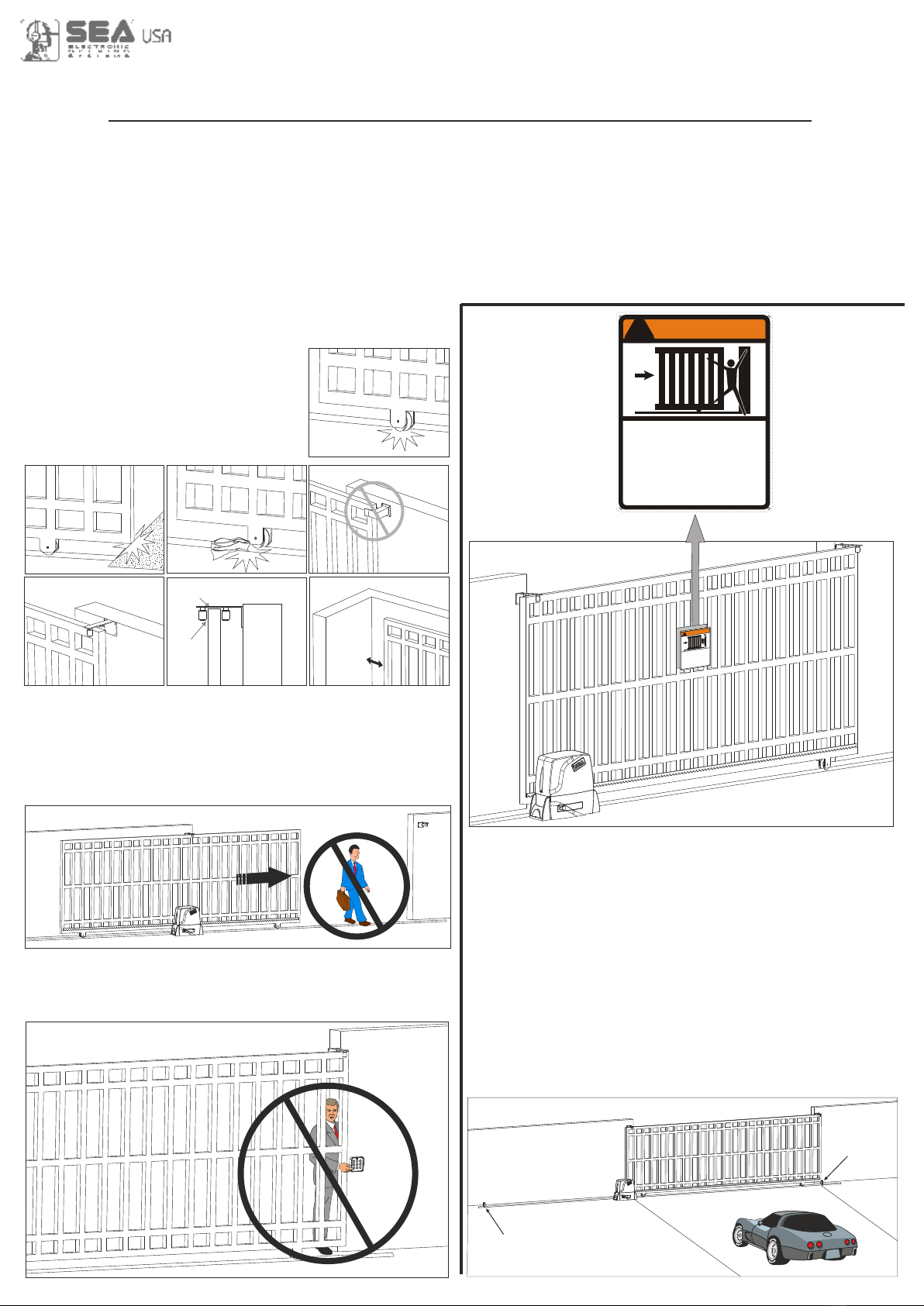
Install the warning signs, on both sides of the gate which
informs the pedestrians about the danger they run when
passing or resting in the environment of the gate (fig. 10).
Important:
For a higher security, SEA advices to install infrared
photocells.
2. PRECAUTIONS
Saturn and Boxer have been created for the automation of
gates used by vehicles only. Pay very much attention to
avoid the crossing of the gate path it is very dangerous for
pedestrians (fig. 8).
Make sure that no person not belonging to the company
somehow activates the automation or acts on it from the
outside (fig. 9).
GATE WARNINGS AND PRECAUTIONS
!
WARNING
Moving Gate Can Cause
Serious Injury Or Death
- KEEP CLEAR ! Gate may move at any time
without prior Warning.
- Do not let children operate the gate or play in
the gate area.
- This entrance is for vehicle only.
Pedestrians must use separate entrance
3. TYPE OF INSTALLATION
A front installation is the right and only possible installation,
it is highly recommended to install two security gate stops
on the two extremities of the rail to prevent the gate from
derailment (fig. 11).
Fig. 10
!
WARNING
Moving Gate Can Cause
Serious Injury Or Death
- KEEP CLEAR ! Gate may move at any time
without prior Warning.
- Do not let children operate the gate or play in
the gate area.
- This entrance is for vehicle only.
Pedestrians must use separate entrance
Fig. 11
Over-Travel Stop
Over-Travel
Stop
1. GATE ARRANGEMENT
The first thing to check is that the gate is in good running order as follows:
a) The gate is rigid and straight and runs smoothly throughout its travel.
b) That the inferior sliding guide-rail is perfectly straight and horizontal to avoid a derailment of the gate (fig. 1);
furthermore it must be free of irregularities and foreign bodies which could obstruct the normal run of the gate (fig. 2 - 3).
c) That the upper guides are not fixed (fig. 4) but furnished with rollers d) that the distance between the end of the gate
(in maximum opening position) and the eventual wall must be at least of 5 inches (fig. 7) which allow the sliding of the
gate without difficulties (fig. 5 and 6).
e) The lower support wheels have
sealed bearings or grease points.
f) The top guide must be
manufactured and installed so that
the gate is perfectly upright.
g) Physical gate stops must be
fitted to prevent the gate coming out
of its guides and track.
Fig. 8
Fig. 9
International registered trademark n. 2.777.971
7
SATURN 1200 FAST 24V
SATURN 1200 FAST 24V
S.500 SUPER FAST
SATURN 500 SUPER FAST 24V
SATURN 1500 24V OILSATURN 1500 24V OIL
SATURN 2000SATURN 2000
BOXER 1000BOXER 1000
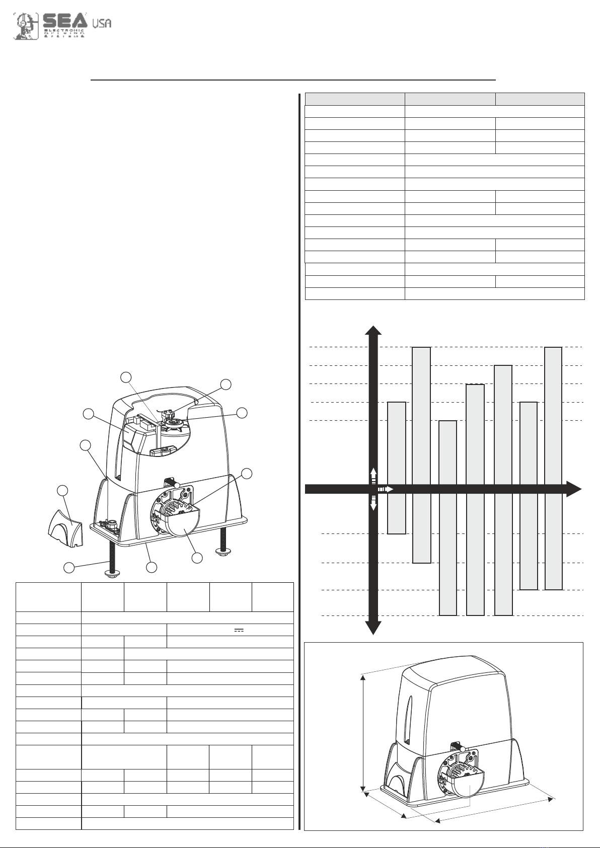
1 Adjustable foundation plate
2 Anchor bolts
3 Pinion protection
4 Adjusting screws cover
5 Pinion
6 Reducer release lever
7 Screw for mechanical
clutch adjustment
(where present)
8 Electronic unit
9 Oil filling up cap
10 Magnetic encoder
MAIN PARTS DENOMINATION
DIMENSIONS (inches)
12.59
13.58
8.46
FEATURES AND SPECIFICATIONS
BOXER 2000BOXER 2000
4409.24 lb
2204.62 lb
SATURN 1000
40%
25%
Use frequency
Gate maximum weight
Motor reducers
SAT.1000
55%
The SATURN and the BOXER are motor reducers
designed for the automation of sliding gates with grease
lubrication or in oil bath, depending on the versions. The
irreversibility of the motor reducers allows a perfect and
safe gate closing, and makes the installation of an elecric
lock unneccessary. In case of electric power cut, the lock
device placed on the front part of the motor reducer allows
the manual opening and closing. The operators are
equipped with an electronic clutch device and adjustable
mechanical clutch (if present), which provides an
adjustment of the thrust on the gate, furthermore the
electronic inversion system (optional) through encoder
makes out of the motor reducers a safe and reliable
operators allowing in a simple way to respect the laws in
force in the country where the product will be installed
10
7
5
3
1
2
4
6
8
9
TECHNICAL DATA
Power supply
Power
Absorbed current
Motor capacitor
Working frequency
Working Temperature
Thermoprotection
Weight
Anticrushing clutch
Protection degree
Pinion Z16 (Z20) speed
Maximum torque
Gate maximum weight
Gate maximum length
Mechanical clutch
Limit switch
120 V (±5%) 50/60 Hz
400W 500W
3,2 A 5,0 A
50 uf 70 uf
55%
-4°F +131°F
302°F
30.86 lb 33.06 lb
Electronic Electronic/Mechanical
IP55
31.16 (36.08) feet/min
55 Nm 70 Nm
2204.62 lb 4409.24 lb
32.80 feet
no yes
Inductive or mechanical
Boxer 1000 Boxer 2000
60%
3306.93 lb
SATURN - BOXER MOTOR REDUCERS USING GRAPHIC
Saturn 500
SUPER FAST
24V
Saturn
1000
Saturn
2000
Saturn 1500
OIL 24V
TECHNICAL
DATA
Power supply
Motor
Power
Absorbed current
Motor capacitor
Working frequency
Working Temperat.
Thermoprotection
Weight
Anticrushing clutch
Protection degree
Pinion Z16 (Z20)
Speed
Maximum torque
Gate max.weight
Gate max.length
Mechanical clutch
Limit switch
1102.31 lb
120V (±5%) 50/60 Hz
120V 24V
400W 500W 100W
3,2 A 5,0 A
50 uf 70 uf -
25% 40% 60%
-4°F +131°F
302°F -
28.66 lb 31.96 lb 31.52 lb
Electronic
Electr./Mech.
Electronic
IP55
31.16 (36.08)
feet/min
55 Nm 70 Nm 0 - 45 Nm 0 - 60 Nm 0 - 65 Nm
2204.62 lb
4409.24 lb
3306.93 lb
1102.31 lb
32.80 feet
No yes -
Inductive or mechanical
Saturn 1200
FAST 24V
(Z20) 78.6
feet/min
(Z16) 62.94
feet/min
(Z20) 49.20
feet/min
2645.54 lb
2645.54 lb
International registered trademark n. 2.777.971

8
Fig. 13
Z16
Z20
4.25 in
4.56 in
MINIMUN DIMENSION Q
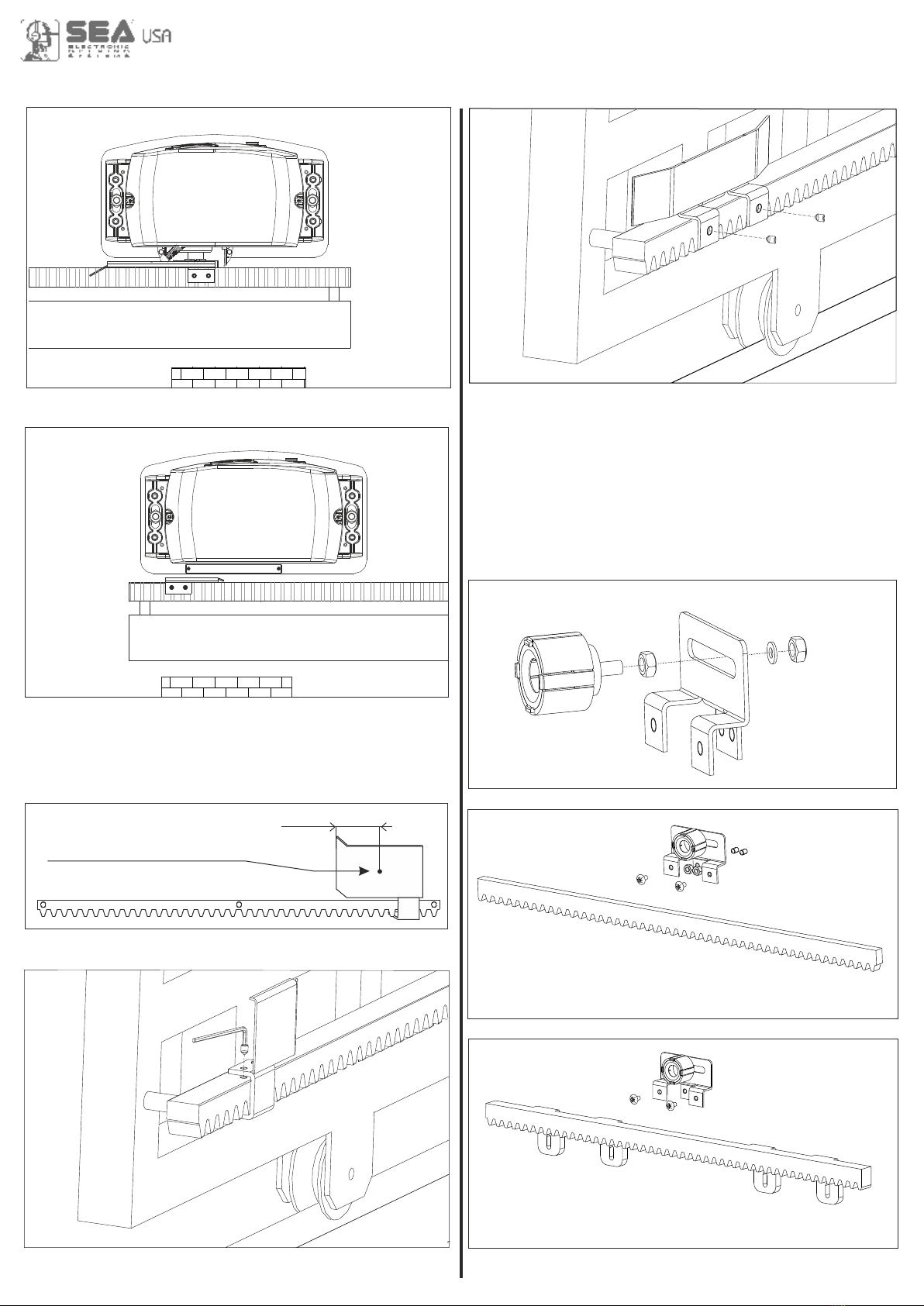
4.2. Before concreting in the plate insert a flexible plastic
duct into the special hole of the plate. Ø 1.18 in. Minimum
4.3. Before concreting in the plate, make sure that it is
perfectly leveled and that the distance of 2,28-2,63 in. as
shown in Fig. 13 is respected.
4. FOUNDATION PLATE ANCHORAGE
To install the foundation plate it is necessary to:
4.1. Prepare a concret basement with the dimensions
shown in Fig. 12 where the foundation plate and the
anchor bolts will be concreted.
NOTE: It is recommended, gate structure permitting, to lift
the foundation plate about 1.96 in. from the ground, in
order to avoid eventual water stagnation.
1.69-2.28
6. FITTING OF THE MOTOR REDUCER
6.1. Insert the 4 grains into the special holes, so that it is
possible to adjust the motor reducer height on the plate
(Fig. 15).
At the end of installation check if the 4 crub screws are
well gripped on the foundation plate.
6.2. Fix the motor reducer to the foundation plate with the 2
included nuts, adjusting the side position (Fig. 16) so to
respect the shown quota in (Fig. 13).
6.3. Remove the closing loading oil cap (red) and
substitute it with that supplied apart provided with the
airhole (black).
Fig. 16
5.90
16.53
9.84
Plinto
Fig. 12
2.28-2.63
2.55
Max 0.19 in.
5. CABLES PASSAGE ARRANGEMENT
Saturn and Boxer are provided with two different holes for
electric cables passage.
It’s very important to make the high - tension (120V~)
cables pass through one hole and the low - tension cables
(24V ) through the other one (Fig. 14)
MECHANICAL INSTALLATION
Fig. 14
Hole 1
Hole 2
Fig. 15
International registered trademark n. 2.777.971
9
Fig. 21
0.059 in.
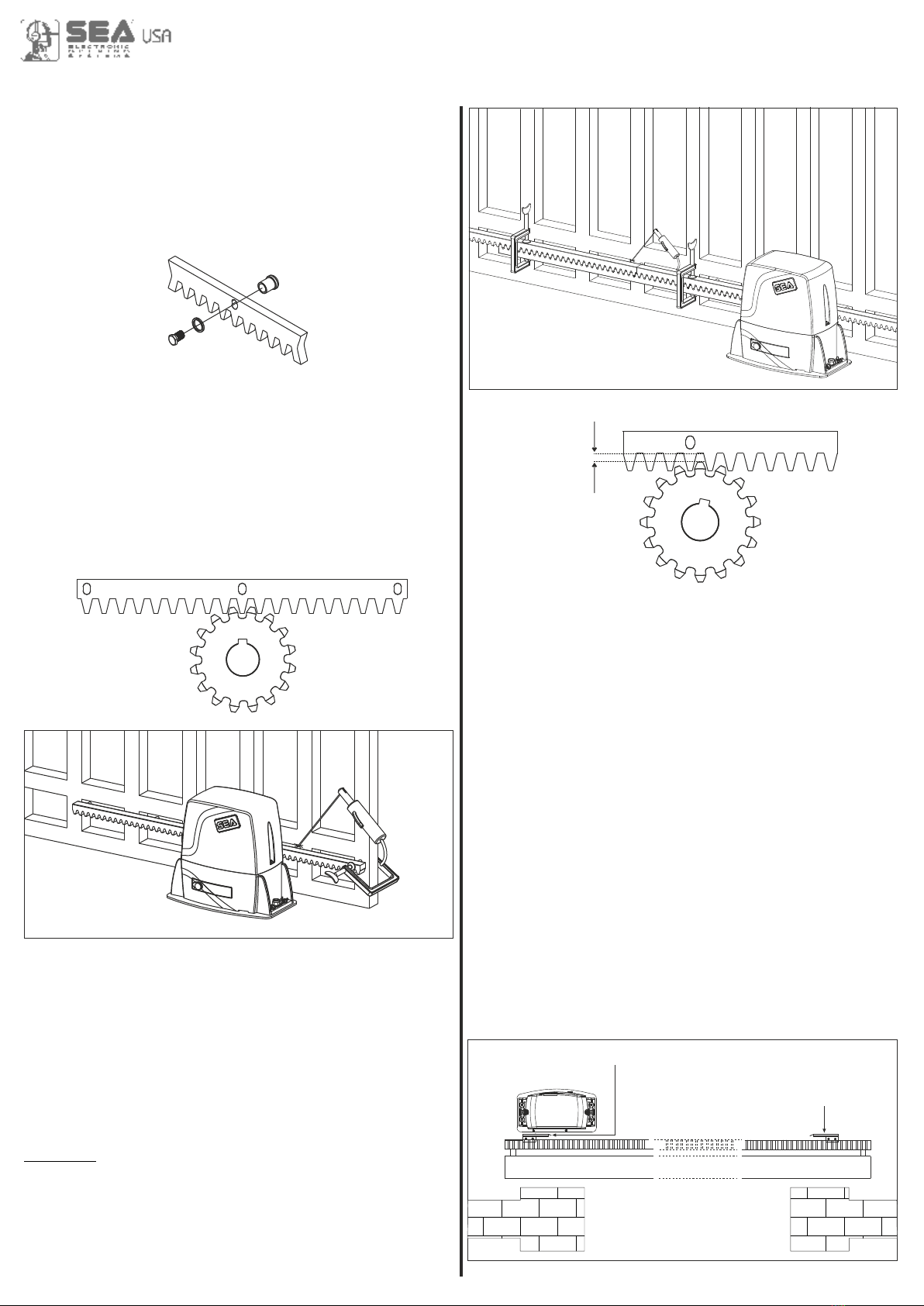
7.4. Make sure that all the gear rack elements are
perfectly aligned and placed correctly (teeth in phase). It’s
suggested to place two aligned elements infront of a third
one as shown in Fig.20;
7.5. Repeat the above described operation for all the
remaining gear rack elements which have to be installed;
7.6. To avoid that the door weights down on the pinion
(Fig.21) lift up the whole rack about 0.059 in.
Warning: Keep a gap of about 0,019 in. between pinion
tooth and gear rack tooth;
7.7. Make sure that the gear rack works at the center of
the pinion along all rack elements, if necessary, adjust the
distance pieces length.
Fig. 18
ABC
Fig. 17 Fig. 20
Fig. 19
8. LIMIT SWITCH ADJUSTMENT
8.1. In order to install and adjust the limit switch in opening,
follow the below mentioned instructions (Fig. 22):
- Take the gate to complete opening,
- Place the small plate on the gear rack so that the limit
switch is (small lever in case of mechanical limit switch
(Fig. 23); small pointers placed on the upper part in case of
inductive limit switch (Fig. 24)) in corrispondence of pointX
which is placed 1.96 in. from the folded side of the small
plate (fig. 25) and fix it with the delivered screws (Fig. 26 -
Fig.27).
8.2. In order to install and adjust the limit switch in closing,
follow the below mentioned instructions (Fig. 22):
- Take the gate to complete closing
- Place the small plate on the gear rack so that the limit
switch is in corrispondence of pointX which is placed 1.96
in. from the folded side of the small plate (fig. 25) and fix it
with the delivered screws (Fig. 26 - Fig.27).
Fig. 22
Limit switch in closing
Limit switch in opening
7. GEAR RACK MOUNTING
7.1. Release the motor and open the leaf completely;
7.2. Fix on each gear rack element the support pawls with
the appropriate lock screws, make sure to put them in the
upper part of the hole (Fig. 17) ;
7.3. Lean the gear rack element on the toothed pinion of
the motor in parallel to the ground slideway of the gate, as
shown in Fig. 18 and electrically weld the central pawl B to
the gate structure (Fig. 19).
Manually move the gate until pawl C is placed
corresponding to the pinion and fix it through electric
welding. Repeat the same procedure for pawl A after
having placed it corresponding to the pinion;
International registered trademark n. 2.777.971
10
Fig. 24
Adjusting the trimmer for braking, placed on the electronic
control unit, it is possible to make the gate stop on the
desired position.
Inductive limit switch
Fig. 26
1.96 in.
X
Fig. 25
Position in which must be the spring (mechanical limit
switch) or the pointer (inductive limit switch)
Mechanical limit switch
Fig. 23 Fig. 27
9. MAGNETIC LIMIT SWITCH
Fig.28
Fig.29
Fig.30
Steel rack
Plastic rack
International registered trademark n. 2.777.971
11
MAX 10 mm
Fig.31
Sliding gate
Magnet
Limit sheet
Rack
Pinion
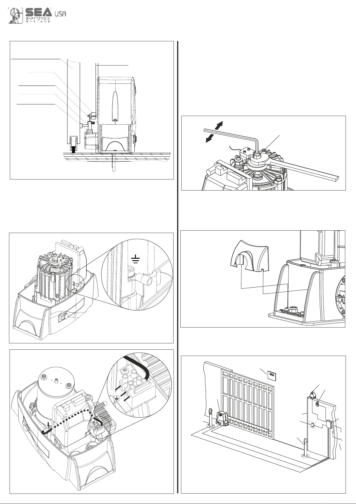
10. GROUNDING (Fig. 32 - Fig.33)
Fig. 32
Fig. 33
F
N
Example: Boxer
Example: Saturn 24V
11. CLUTCH ADJUSTMENT (Where present)
11.1. Switch off electric power.
11.2. In order to adjust the clutch it is necessary to:
- Act on the scrub screw “A” (Fig. 34) as follows:
- Turning clockwise = less clutch sensibility/more thrust
force
-Counter clockwise = more clutch sensibility/less thrust
force
12. SCREW COVER MOUNTING
At the end of the mechanical installation and after having
executed all the required adjustments, mount the two
screw covers on the operator as shown in Fig. 35.
Fig. 35
Fig. 34
A
Ex. Boxer
+ power
- sensibility
- power
+ sensibility
13. ELECTRIC CONNECTIONS OF THE
INSTALLATION (Fig. 36)
1) Saturn - Boxer
2) Photocell Sx
3) Photocell Dx
4) Mechanical safety edge
5) Key push botton
6) Flasher
7) Receiver
8) Warning notice
9) Junction box
10) Differential
Fig. 36
1
2
3
4
10
5
6
7
8
9
2
The cable mesures are indicated in mm
International registered trademark n. 2.777.971
12
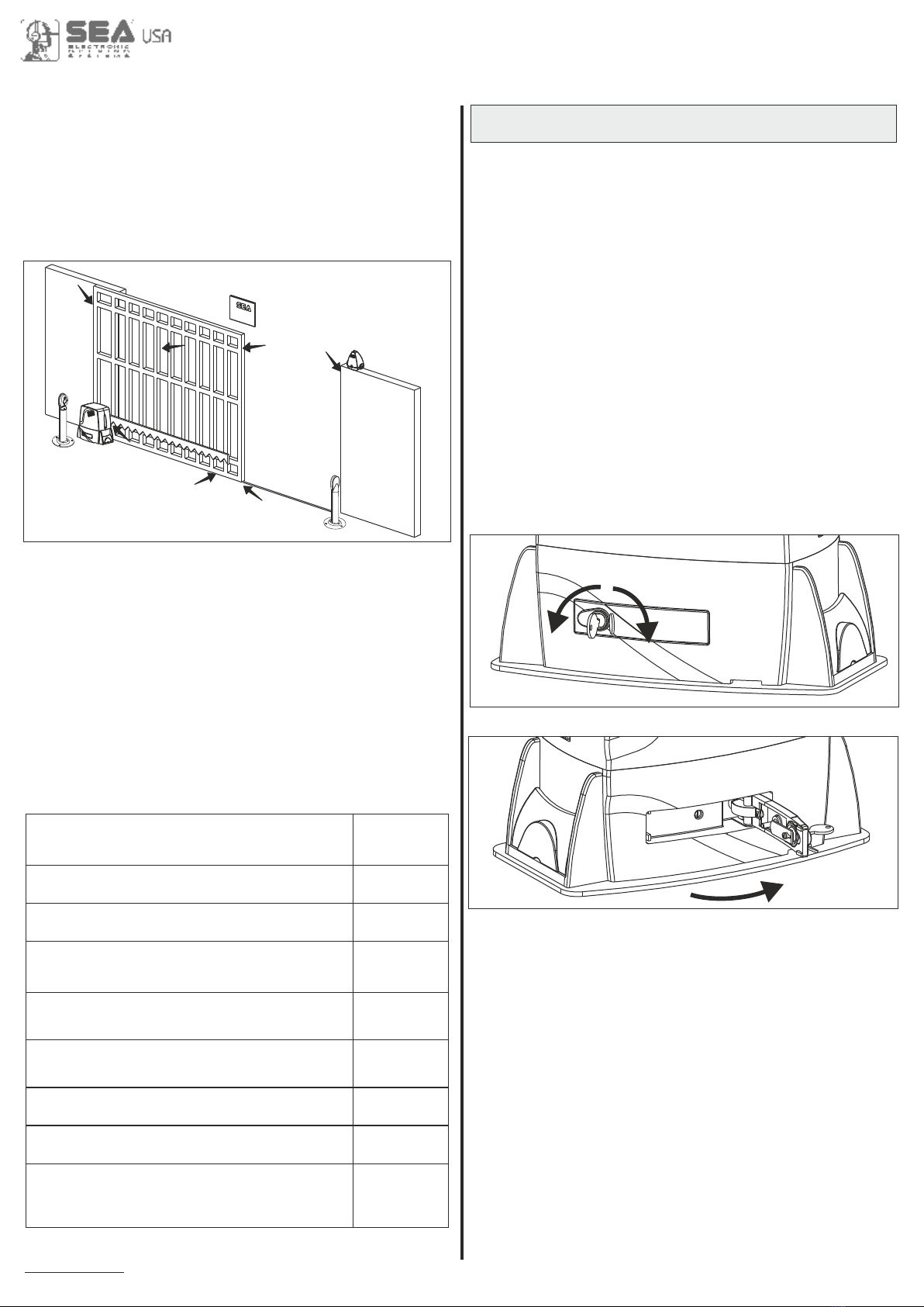
14. RISK EXAMINATION
The points pointed by arrows in Fig. 37 are potentially
dangerous. The installer must take a thorough risk
examination to prevent crushing, conveying, cutting,
grappling, trapping so as to guarantee a safe installation
for people, things and animals (Re. Laws in force in the
country where the installation has been made.)
15. NOTICE
SEA USA Inc. can not be deemed responsible for any
damage or accident caused by product breaking, being
damages or accidents due to a failure to comply with the
instructions herein. The guarantee will be void and the
manufacturer responsibility will be nullified if SEA USA Inc.
original spare parts are not being used. The electrical
installation shall be carried out by a professional
technician who will release documentation as requested
by the laws in force. Packaging materials such as plastic
bags, foam polystyrene, nails etc must be kept out of
children’s reach as dangers may arise.
Fig. 37
16. PERIODIC MAINTENANCE
All the above described operations must be done
exclusively by an authorized installer.
Check the oil level (where present)
(Use the oil level rod)
Change oil
Check the release functionality
Check the clutch functionality
(where present)
Check the distance between pinion and
gear rack (0,059 in.)
Check the usury status of pinion and
gear rack
Check the fixing screws
Check the connection cables integrity
Check limit switch functionality and status
in opening and closing and the related
small plates
Annual
4 years
Annual
Annual
Annual
Annual
Annual
Annual
Annual
Open
Close
Fig. 38
Fig. 39
17. RELEASE SYSTEM FOR SATURN AND BOXER
17.1. In order to release do as follows:
-Open the lock cover, insert the key and rotate it 90°
clockwise (Fig. 38).
- Pull the release lever until it stops, about 90°
approximately (Fig. 39).
Note: when you pull the release lever, the electronic
control unit receives a stop impulse thanks to a
micro-switch placed inside.
17.2. In order to relock do as follows:
- Push the release lever to complete closing.
- Rotate the key counter-clockwise and extract it.
- Close the protective lock cover.
Once the lock has been restored the electronic control unit
reactivates
Page for both instaler and user
International registered trademark n. 2.777.971

13
GENERAL WARNING: Installation must be realized using parts and accessories approved by SEA. SEA is
not responsible for incorrect installations and/or non-compliance with safety standards according to the law
in-force. SEA is in no way liable for any damages and/or malfunctioning due to using parts and accessories
non-compliant with the UL325 safety standards.
ORDERS: Orders are processed upon approval by SEA. Buyers must confirm orders by sending a written
Purchase Orders to SEA. Purchase Orders are intended as confirmation of orders and binding for the buyer,
which accepts SEA sales condition.
QUOTATION: Quotation and special offers with a non-specified duration expires automatically after 30 days.
PRICES: Prices are based on the Price List in force. Discounts and quotation from Sales Rep. and other
selling branches must be approved by SEA. Prices are F.O.B SEA Warehouse in Miami and do not include
shipments costs. SEA reserves the right to modify the price list at any time and provide notice to its sales
network.
PAYMENT: Method of payments and terms are notified by SEA and displayed on the commercial invoice.
DELIVERY: The delivery time on the invoice is not binding and represents an estimated delivery. Shipments
costs will be charged to the buyer and SEA is not responsible for delays and/or damages occurred to the
products during shipment.
COMPLAINS: Complains and/or claims must be notified to SEA within 7 business days after receiving the
products. Claims and complains must be supported by original documents. Customer must contact the
factory for instructions and authorization. Merchandise returned for credit must be current, uninstalled and
unused and returned in its original packaging. Freight must be pre-paid on all authorized returns.
REPAIRS: Repairs and parts are subject to the availability in stock. Shipment of products for repairs must be
pre-paid by the customer. Products shipped without authorization, sender’s details and description of the
problems will be refused. Customers must contact SEA for instructions.
WARRANTY: for the original buyer only:
Hydraulic and oil-bath motors: 36 months warranty from the date of invoice on manufacturing, assembling
and workmanship defects.
Electro-mechanic motors and electronic control systems: 24 months warranty from the date of invoice on
manufacturing, assembling and workmanship defects.
Lepus and Full Tank Standard model: 60 months warranty from the date of invoice on manufacturing,
assembling and workmanship defects.
No warranty will be recognized for damages due to incorrect installation and/or improper use for which the
product was intended. SEA warranty obligations shall be limited to repair or replace the defective
product/parts at SEA option, upon examination of the products by SEA technical Staff. All replaced parts must
remain property of SEA. The warranty status of the product remains an unquestionable assessment of SEA.
Buyer must ship pre-paid defective products. Products under warranty will be returned pre-paid by SEA.
Recognized defects, whatever their nature, will not produce any responsibility and/or damage claims to SEA
USA Inc and SEA s.r.l. Warranty shall not cover any required labor activities. Warranty will in no case be
recognized if alterations and any other changes will be found on products. Warranty will not cover damages
caused by carriers, expendable materials and faults due to improper use with the products specifications. No
indemnities are recognized during repairing and/or replacing of the products under warranty. SEA USA Inc.
and SEA s.r.l. decline any responsibility for damages to person and objects deriving from non-compliance
with safety standards, installation instructions or use of the products sold. It is intended that warranty will be
recognized only on products bought through the SEA authorized network. Products must be installed by
professionals. No warranty will be recognized if products are installed directly by the final user. Warranty does
not apply in case of unexpected events such as fire, flood, electrical power surge, lightning, vandalism and
others.
SEA USA Inc. is not responsible for errors in technical information printed in catalogs and installation
manuals.
SALES CONDITIONS
International registered trademark n. 2.777.971

Notes


web site: www.sea-usa.com
e-mail: [email protected]
International registered trademark n. 2.777.971
SEA USA Inc.
10850 N.W. 21st unit 160 DORAL MIAMI
Florida (FL) 33172
Phone:++1-305.594.1151 Fax: ++1-305.594.7325
Toll Free: 800.689.4716
This manual suits for next models
6
Table of contents
Other SEA Gate Opener manuals

SEA
SEA ALPHA Series Original instructions

SEA
SEA SUPER FULL TANK Series Original instructions

SEA
SEA LEPUS Series User manual

SEA
SEA TORG Instruction manual

SEA
SEA TAURUS Instruction manual

SEA
SEA LYRA User manual

SEA
SEA FULL TANK 100 User manual

SEA
SEA GATE 1 DG R2BF User manual

SEA
SEA ALPHA 200 PLUS User manual

SEA
SEA FLIPPER User manual

SEA
SEA ALPHA 200 STANDARD User manual

SEA
SEA TORG Series Instruction manual

SEA
SEA TAURUS BOX 1000 User manual

SEA
SEA JOINT Original instructions

SEA
SEA FIELD Series User manual

SEA
SEA FLIPPER 110V User manual

SEA
SEA SURF K 500 User manual

SEA
SEA SATURN User manual

SEA
SEA JOINT Original instructions

SEA
SEA Libra Mini Tank Original instructions


