Microdyn Nadir BIO-CEL EASY User manual

BIO-CEL®EASY
User Manual

BIO-CEL® EASY | USER MANUAL
MANN+HUMMEL Water & Fluid Solutions | REVISION DATE: 09/06/2021
2
Contact
Europe
Germany: +49 611 962 6001
Italy: +39 0721 1796201
info@microdyn
-nadir.com
Americas
USA: +1 805 964 8003
sales.mnus@microdyn
-nadir.com
Asia
Singapore: +65 6457 7533
China: +86 10 8413 9860
waterchina@mann
-hummel.com

BIO-CEL® EASY | USER MANUAL
MANN+HUMMEL Water & Fluid Solutions | REVISION DATE: 09/06/2021
3
Table
of Contents
1Introduction ......................................................................................................................................5
2Handling and Interim Storage .................................................................................................6
3Product Description....................................................................................................................7
3.1
ACCESSORIES & SPARE-PARTS................................................................................................ 8
4Process Description ...................................................................................................................9
4.1
MECHANICAL PRE-TREATMENT OF WASTEWATER.................................................................. 9
4.2
BIOLOGICAL PROCESSES ......................................................................................................... 9
4.3
FILTRATION PROCESS ...............................................................................................................11
4.4
CLEANING PROCESS ................................................................................................................12
5Process Design ......................................................................................................................... 16
5.1
BIO-CEL EASY P&ID & FUNCTIONAL DESCRIPTION .................................................................16
5.2
EQUIPMENT & TANK DESIGN ....................................................................................................19
6Commissioning ......................................................................................................................... 22
6.1
PRE-COMMISSIONING .............................................................................................................. 22
6.2
WATER COMMISSIONING ......................................................................................................... 23
6.3
POST-COMMISSIONING CHECK ............................................................................................... 24
7Performance Monitoring ........................................................................................................ 25
7.1
PERMEABILITY MONITORING................................................................................................... 25
7.2
MONITORING DIFFUSER PERFORMANCE ................................................................................ 26
8Decommissioning and Storage............................................................................................ 27
8.1
STORAGE OF WETTED MEMBRANES DURING MAINTENANCE ............................................... 27
8.2
STORAGE OF IMMERSED MODULES OUT OF OPERATION...................................................... 27
8.3
LONG TERM REMOVAL & STORAGE........................................................................................ 27
9Disassembly & Disposal ........................................................................................................ 29

BIO-CEL® EASY | USER MANUAL
MANN+HUMMEL Water & Fluid Solutions | REVISION DATE: 09/06/2021
4
9.1
DISASSEMBLING THE MODULE ............................................................................................... 29
9.2
DISPOSAL OF COMPONENTS & MODULE ................................................................................ 29
9.3
RETURNING DAMAGED MODULE............................................................................................. 29
9.4
DISPOSAL OF PACKAGING ...................................................................................................... 29
Appendix 1: Operational Sequence Chart.................................................................................30

BIO-CEL® EASY | USER MANUAL
MANN+HUMMEL Water & Fluid Solutions | REVISION DATE: 09/06/2021
5
1Introduction
This user manual is intended to provide general information only. For further details, please refer to the general BIO-CEL® User
Manual or contact your local MANN+HUMMEL Water & Fluid Solutions (WFS) representative. Please read the following instructions
carefully before handling BIO-CEL®EASY modules; inappropriate handling or operating of the modules may lead to decreased
performance or even damage.
This information is based on our current knowledge and is intended to provide only general notes on the product. At any time, we
reserve the right to make modifications due to new developments. Any existing property rights must be observed. Our products
are sold under our General Conditions of Purchase and Sale.
Intended use:
BIO-CEL EASY is designed for the treatment of municipal and industrial wastewater.
BIO-CEL EASY is not designed for the filtration of food materials, drinking water or flow different from wastewater as mentioned
above.
Figure 1. BIO-CEL®EASY

BIO-CEL® EASY | USER MANUAL
MANN+HUMMEL Water & Fluid Solutions | REVISION DATE: 09/06/2021
6
2Handling and Interim Storage
The following are recommendations for safe storage and transport of BIO-CEL®EASY prior to installation.
Please make sure that the required materials are available on site.
Caution: Transport with complete packaging only.
-Keep module in original packaging for further storage and transportation purposes and to move module to location
of installation.
- Leave module on pallet until beginning of installation.
To transport and temporarily store the module before installation, please consider the safety instructions listed below. These
instructions are also listed on the packaging. The membrane modules have a shelf life of 12 months when stored according to the
conditions below. More details regarding decommissioning and storage are given in section 8.
Transport with forklift
only.
Do not damage
outer packaging.
Handle the product
with care.
Packaging is
top-heavy.
Store packaging
upright with arrows
directed upwards.
Do not stack the modules.
Protect from direct
sunlight.
Store preserved modules
in the following
temperature range only:
5°C - 40°C
(41°F - 104°F).
Protect from
moisture
(< 70 % ambient
humidity).
When handling the module, please make sure to follow below safety notes.
Wear a safety helmet.
Wear safety shoes.
Wear safety gloves.
Read the manual before
using the product
BIO-CEL® EASY | USER MANUAL
MANN+HUMMEL Water & Fluid Solutions | REVISION DATE: 09/06/2021
7
3Product Description
BIO-CEL®EASY is a small but mighty MBR system built for customers whose water treatment needs fall into the 10 – 100 m3/d
‘sweet spot’ for the modules. This simple and efficient MBR module is easy to design, assemble, connect, move, and expand in any
customer facility. The BIO-CEL EASY module fits perfectly in the filtration tank: BIO-CEL®EASY TANK.
The perfect pair of tank and module ensures a plug-and-play experience.
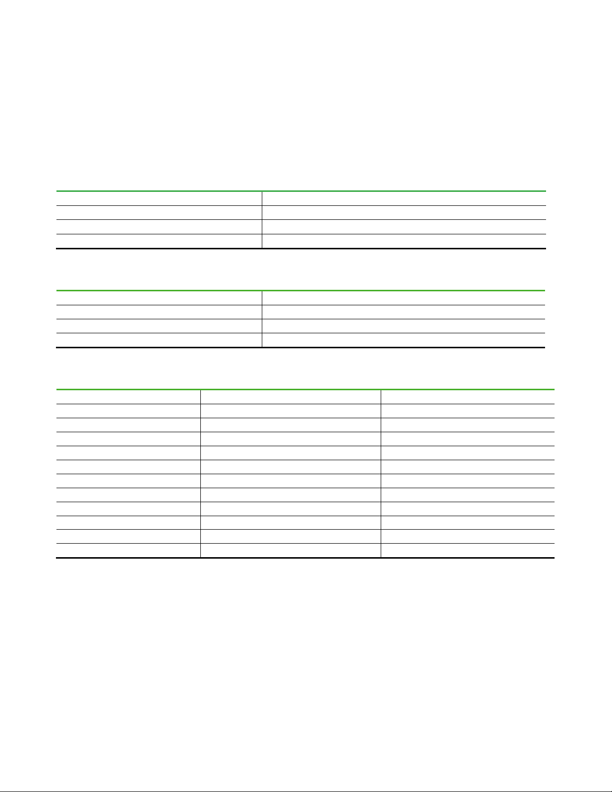
Please find general information on membrane characteristics, module specifications, and physical dimension on our data sheet
online (reprinted here in part).
Table 1. Membrane characteristics
Membrane NADIR®UP150
Membrane Polymer Polyethersulfone (PES)
Nominal Pore Size 0.04 µm
Preservative Glycerine 20 % / Sodium benzoate 3 %
Table 2. Module specifications
Housing Material Options Stainless Steel 1.4301/304 (V2A)
Drainage Layer Polyester (PET)
Diffusors Material Options Membrane hose: EPDM
Nominal Membrane Area 50 m2(538 ft2)
Table 3. Physical dimensions
Module Tank
Length 674 mm (2.2 ft) 1,066 mm (3.5 ft)
Width 590 mm (1.9 ft) 706 mm (2.3 ft)
Height 1,351 mm (4.4 ft) 2,036 mm (6.6 ft)
Dry Weight 95 kg (209 lb) 210 kg (463 lb)
Wet Weight without Solids 125 kg (275 lb) N.A.
Maximum Load for Liftingc330 kg (727 lb) N.A.
Filtration Tank Minimal Water Level 1,633 mm (5.3 ft) N.A.
Water Level N.A. 1,650 mm (5.4 ft)
Connection for Permeate ¾” G (inner thread) ¾” G (inner thread)
Connection for Aeration 1 ½” G (outer thread) 1 ½” G (inner thread)
Connection for Sludge Recirculation N.A. 1 ½”
c Sludge deposit must be removed before lifting unit

BIO-CEL® EASY | USER MANUAL
MANN+HUMMEL Water & Fluid Solutions | REVISION DATE: 09/06/2021
8
3.1
ACCESSORIES & SPARE-PARTS
Table 4 and Figure 2 show available accessories and spare parts. To ensure proper installation and operation of BIO-CEL®EASY,
certain accessories are necessary if the module is purchased not already installed in the tank. No spare parts are typically required
for BIO-CEL EASY within the first five years of operation. If spare parts are needed, they may be ordered as per the Table 4.
Table 4. Accessories & spare parts
Position Spare Part Remarks
1
BIO-CEL® EASY Membrane Stack
1 pcs membrane stack only, packed in a box. The BIO-CEL EASY consist of 2
membrane stacks.
2
BIO-CEL® EASY Permeate Piping Permeate piping for installation in standard BIO-CEL EASY tank
3
BIO-CEL® EASY Diffusor Set Set of 4 diffusors including O-rings
4 BIO-CEL® EASY Permeate Piping Permeate piping for installation in standard BIO-CEL EASY tank
5 BIO-CEL® EASY Tank Steel tank made of SS304 including steel parts to fix the BIO-CEL EASY in the tank.
6 BIO-CEL® EASY Frame Set of all steel parts (excluding tank)
Figure 2. BIO-CEL®EASY accessories & spare parts
BIO-CEL® EASY | USER MANUAL
MANN+HUMMEL Water & Fluid Solutions | REVISION DATE: 09/06/2021
9
4Process Description
4.1
MECHANICAL PRE-TREATMENT OF WASTEWATER
The selection of an appropriate pre-treatment process is essential for the efficient operation of the downstream processes in any
wastewater treatment plant. For MBRs, the pre-treatment process is essential as certain materials may exacerbate fouling/ragging
or even cause damage to the membrane.
The fine screening is the most critical component in the MBR pre-treatment process. The fine screens must be selected, designed,
installed, operated, and maintained properly to ensure sufficient protection of membranes over the life of the membranes. It is
important to test and verify the performance of the fine screening system for both hydraulic performance and removal efficiency
to ensure they meet design specifications.
The fine screening requirements for the BIO-CEL®EASY are as follows:
•Minimum: screens with ≤2 mm (0.08 inches) round-hole openings.
•The screen design, installation, and operation must not allow overflow or bypass of unscreened wastewater to the MBR
system in any circumstances.
The screening requirements for industrial applications may be different from those for municipal applications depending on the
nature of solids in the wastewater and what needs to be removed prior to the membranes.
4.2
BIOLOGICAL PROCESSES
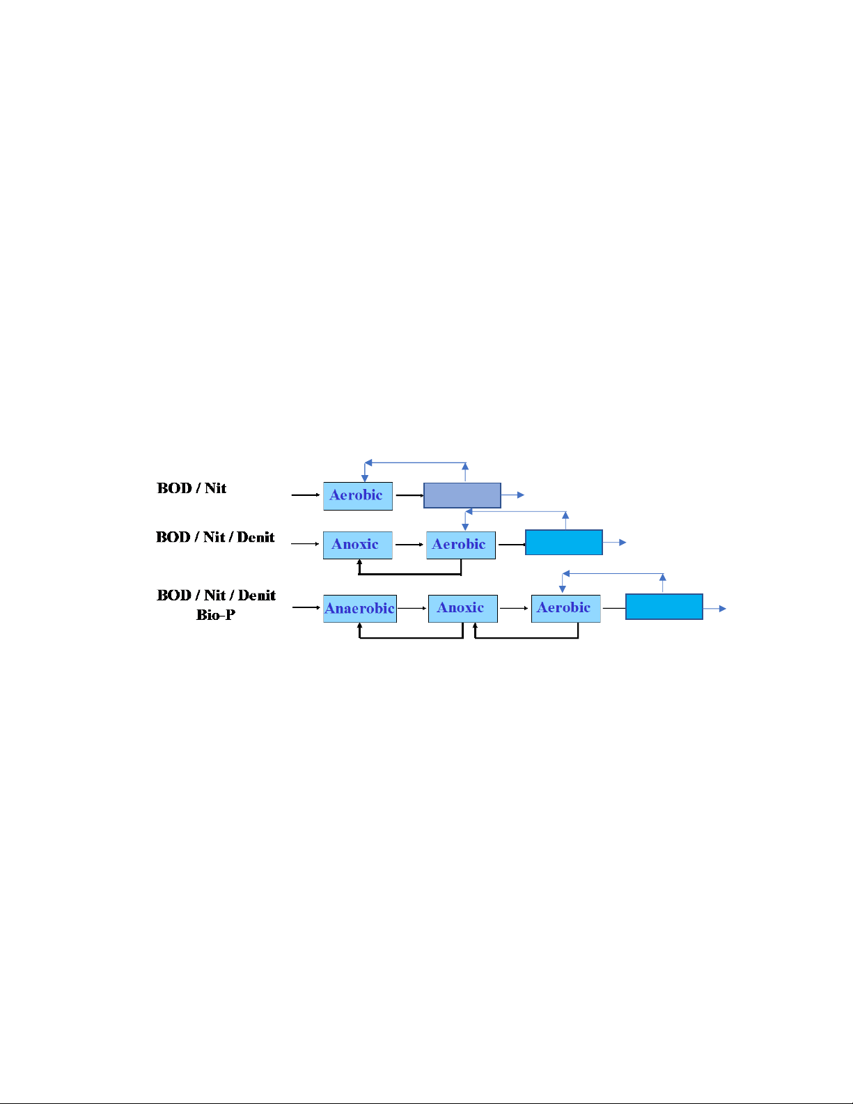
The most common biological configurations before the membrane filtration step are as follows:
In any biological configuration, the membranes should always filter mixed liquor from aerobic bioreactors. The mixed liquor is then
recirculated and returned from the membrane tank or from the aerobic tank back to the other zones depending on overall process
configurations. From the membrane point of view, however, the design considerations are always related to aerobic bioreactors.
The performance of systems using BIO-CEL EASY depends on the whole process including pre-treatment, biological treatment
process and mixed liquor quality. The mixed liquor filtered by the systems using BIO-CEL EASY must meet the quality
requirements listed in table 5. This list is intended for municipal wastewater treatment and additional criteria may be required for
other applications. The specific effluent quality requirements may also require additional mixed liquor qualities that are not listed
here. MANN+HUMMEL WFS should be consulted for specific cases.
A effective pre-treatment and biological treatment are the requirements for a well working filtration. In addition sludge filterability
testing may be used for monitoring the condition of sludge. Poor filterability may indicate high fouling potential and may lead to
low filtration performance. A detailed description of sludge filterability monitoring parameters is provided in Table 5.
Figure 3.
Overview of biological configurations
MBR
MBR
MBR

BIO-CEL® EASY | USER MANUAL
MANN+HUMMEL Water & Fluid Solutions | REVISION DATE: 09/06/2021
10
Table 5. Characteristics of a well-working biology
Parameter Acceptable Range Target Comments
Temperature
5-40°C
(41-104°F)
10-30°C
(50-86°F)
Lower temperatures will inhibit the bacteria and cause
insufficient BOD/COD removal
pH
6-8 7
MLSS Biology
lower than
membrane tank
6-10 g/L
MLSS Membrane Tank
< 15 g/L
6-10 g/L
10-12 g/L for PDF 1,
PHF
2
It may be required to adjust RAS flow rate to ensure the limits
are not exceeded during PHF events
Sludge Loading Rate
(F/M Ratio)
0.1-0.22 kgCOD/
(kgMLSS·d)
0.10 to 0.16
kgCOD/
(kgMLSS·d)
This assumes the sludge has a typical MLVSS/MLSS ratio of
0.75-0.8. In case of high inert content, the lower F/M-ratio
should be used. Alternatively, the F/M-ratio can be expressed
as recommended range of 0.13-0.19 kg COD/(kgMLVSS·d)
Dissolved
Oxygen (DO)
> 0.5 mg/L ≥1.0 mg/L
Relevant for the mixed liquor that goes into the membrane
filtration tanks
Sludge Volume
Index (SVI)
< 200 ml/g < 150 ml/g
Values higher than 200 ml/g will require biological
optimization
Sludge Retention
Time (SRT)
> 15 d 16-22 d
A sludge age of 10 days is acceptable for tropical systems
with complete nitrification and denitrification
Hydraulic Retention
Time (HRT)
> 6 h average
> 4 h for MDF3,
PHF
Soluble BOD5
< 5 mg/L < 1 mg/L
Soluble COD
< 50 mg/L 10-30 mg/L
Soluble Ammonia
< 2 mg/L < 1 mg/L Must be < 2 mg/L 100% of the time
Trash Content
< 1 mg/L of material
greater than 2 mm
< 10 mg/L of material
greater than 1 mm
Tested monthly per Mixed Liquor Sieve Test
FOG in Membrane
Tank
< 10 mg/L
< 2 mg/L
Notes:
General design/operation of MLSS above target level is possible but not recommended and needs special consideration in the
warranty contract.
The waste water load must be aerobically biodegraded until all residual BOD is removed and only a residual COD is present as
hard COD (non-biodegradable).
While complete nitrification and denitrification processes are not required for membrane operation, better membrane
performance is seen in systems with complete nitrification and denitrification.
Soluble COD for industrial applications may be higher (piloting is strongly recommended to determine applicable process
parameter). These limits are for municipal wastewater treatment and required permeate quality.
The MBR system should have proper pre-treatment, as discussed in Section 4.1, to remove sufficient amounts of FOG, sand,
coarse materials, and trash using fine screening. These are not part of the biological design but will impact the overall sludge
quality and membrane performance.
1 Peak Daily Flow (PDF)
2 Peak Hourly Flow (PHF)
3 Maximum Day Flow (MDF)

BIO-CEL® EASY | USER MANUAL
MANN+HUMMEL Water & Fluid Solutions | REVISION DATE: 09/06/2021
11
4.3
FILTRATION PROCESS
The main operation of BIO-CEL®MBR membrane modules involve repeated production cycles of filtration followed by a short
interval of mechanical cleaning that may consist only of backwash, relaxation, or a combination of the two. The duration of the
production cycle is the sum of the filtration duration plus the relaxation/backwash duration and the time required for valve switch-
over.
Filtration refers to the use of a vacuum (created by a permeate pump) as the driving force to induce water through the membrane
(from the outside of the membrane to the inside) to produce permeate. During filtration, there is a net flow of mixed liquor or feed
water solids toward the membrane surface. Some of this solid accumulation at the membrane surface is reduced by aeration.
Relaxation refers to a short period when filtration is stopped (by stopping the permeate pump or closing the permeate valve in
gravity flow operations) while membrane aeration is continued. During relaxation, there is a net flow of mixed liquor or feed water
solids away from membrane surface.
Backwash or, back pulse, refers to a short period when the permeate flow direction is reversed (compared to filtration). This
creates positive pressure and causes permeate flows from inside of the membranes to the outside. This cleaning uses permeate
produced during the production mode and is taken either from a permeate collection manifold or directly from a CIP/backwash
reservoir. During backwash, there is a net flow of mixed liquor or feed water solids away from membrane surface.
Backwash or relaxation (depending on operation type) occurs automatically during a normal production cycle. The duration and
frequency are an input depending on types of operation. The duration can be fine-tuned by the operator to address varying
operational conditions.
The following table shows the range of acceptable durations for filtration, relaxation, and backwash cycles for a BIO-CEL MBR
system.
Table 6. Durations for filtration, relaxation, and backwash for different sequence types
Cycle Step
Mixed Cycle
Relaxation Only
Filtration
510 s 540 s
Relaxation
30 s 60 s
Backwash
30 s -
Relaxation
30 s -
Notes:
The values in the Table 6 are standard values to start with. If the performance is not within acceptable ranges, the filtration,
relaxation, and/or backwash cycle time may be increased/decreased accordingly. Make sure that the pumps are designed to
handle a net/gross flux ratio of minimum 80%.
If the relaxation cycle is too short, it may reduce physical cleaning efficiency and may cause excessive or irreversible fouling. The
chemical cleaning frequency may also increase.
Backwash affects the system’s efficiency since produced permeate is returned into the process fluid and must be re-extracted.
It is important to allow enough time for the pump to ramp up and ramp down during backwash only cycles. This will prevent the
membranes from experiencing sudden pressure shocks. More details may be found in the BIO-CEL MBR PLC description.
For some venting options, the possibility for regular backwash is mandatory. Please make sure a suitable venting option is used.
BIO-CEL EASY produces very high permeate water quality. The pore sizes of the BIO-CEL EASY membrane are selected such that
all particulate materials (e.g. suspended solids) are rejected. However, dissolved and soluble materials such as dissolved organics,
dissolved phosphorous, or nitrates must be converted to a solid form in order to be removed by the membranes. This can be
achieved using biological treatment, precipitation, or other methods.
The Table 7 summarizes the permeate quality that can be achieved using BIO-CEL MBR modules for municipal applications
considering that the systems are designed, built, and operated according to MANN+HUMMEL WFS guidelines.

BIO-CEL® EASY | USER MANUAL
MANN+HUMMEL Water & Fluid Solutions | REVISION DATE: 09/06/2021
12
Table 7. Achievable permeate quality
Effluent Quality Parameter Expected Permeate Quality Achievable Permeate Quality
BOD5
Equal to soluble BOD5concentration in mixed liquor
< 1 mg/L
TSS
< 5 mg/L
< 2 mg/L
Turbidity
< 0.5 NTU
< 0.2 NTU
SDI
< 3
< 3
Total Phosphorous
Equal to soluble Total Phosphorous concentration in mixed
liquor
< 0.1 mg/L
Ammonia
Equal to soluble ammonia concentration in mixed liquor
< 0.1 mg/L
Total Nitrogen
Equal to soluble TN concentration in mixed liquor
< 3 mg/L
Bacteria Removal
> log 6
> log 6
Notes:
BOD5level is achievable only with appropriate biological system design and temperature.
Ammonia level is achievable only with appropriate biological system design and temperature.
Total nitrogen level is achievable only with appropriate biological system design and temperature.
Total phosphorous level is achievable with appropriate coagulant addition system.
The standard analytical method used for measuring total suspended solids (TSS) lacks precision at < 5 mg/L. A more precise
method is to use continuous online turbidity measurement. This is more accurate for the low turbidity ranges expected for
permeate quality.
Sampling procedures, volume, and location to be determined in detail.
Accurate microbiological results require frequent (very case specific) permeate piping disinfecting and proper permeate piping
design. Log removal values can vary based on feed water quality.
The SDI measurement procedure is described in the BIO-CEL®MBR Operation and Maintenance Manual.
4.4
CLEANING PROCESS
MANN+HUMMEL WFS recommends three types of chemical cleaning procedures.
•Maintenance Cleaning: Maintenance cleanings should be performed regularly and act as preventative maintenance for
the system. Maintenance cleanings are typically performed several times a month using lower concentrations of chemicals
for short periods of time (e.g. 1-2 hour). This cleaning is intended to maintain a sanitized system and to prevent significant
growth of fouling deposits or scales on membrane surfaces and within permeate piping. It is recommended to set up the
systems to perform maintenance cleaning automatically.
•Extended Maintenance Cleaning: The Extended Maintenance Cleaning is usually performed several times a year using
higher concentrations and fill volumes of chemicals for longer periods of time compared to the standard maintenance
cleaning. This cleaning is intended to significantly recover permeability and remove fouling deposits on membrane surfaces.
•Recovery Cleaning: This cleaning uses clean water and is intended to remove all fouling residuals from membrane
surfaces and “recover” membrane permeability close to its initial or acceptable value. It is recommended to use warm water
for a higher cleaning efficiency. The recovery cleaning is not part of routine maintenance but may be required in specific
cases when extended maintenance cleaning is not effective anymore. A Recovery Cleaning implies a module inspection and
removal of dewatered sludge if present.
Depending on the type of fouling and required cleaning, a sodium hypochlorite solution, citric acid solution, or both may be
required. Sodium hypochlorite is used to remove organic and biological fouling from the membrane while citric acid is used to
remove mineral scaling such as iron, metal salts, calcium salt, and other scaling compounds.
MANN+HUMMEL WFS recommends using these two cleaning agents. For more severe fouling or scaling, MANN+HUMMEL WFS
may be contacted for alternative chemical cleaning solutions and procedures.
The general chemical cleaning data must be considered before conducting chemical cleanings to maintain the integrity of the
membrane module. Table 8 shows general chemical data as a guidance to keep the given limits and thresholds.
BIO-CEL® EASY | USER MANUAL
MANN+HUMMEL Water & Fluid Solutions | REVISION DATE: 09/06/2021
13
Table 8. General chemical cleaning data
Parameter Units
pH Range (Operation/Cleaning)
2-11
Temperatures (Operation/Cleaning)
5-40°C (41-104°F)
Sodium Hypochlorite Target Concentration
200-2000 mg/L*
Total Chlorine Resistance
1,000,000 ppm•hours
Hydrogen Peroxide Target Concentration
0.5-1 wt% *
Citric Acid Target Concentration
0.2-1 wt % *
Total Soaking Time
1-24 hours
Chemical Fill Volume without Piping
2-5 L/m2(0.05-0.12 gal/ft2)
Backwash Flux with/without Chemicals
5-15 LMH (3-9 GFD)
Membrane Sheet Inner Volume
1 L/m2(0.024 gal/ft2)
TMP Limit During Filtration -400 mbar (-5.8 psi)
TMP Limit During Cyclic Backwash / Cleaning +150 mbar (+2.2 psi)
*It must be ensured that the allowed pH range (2-11) is not exceeded in any case.
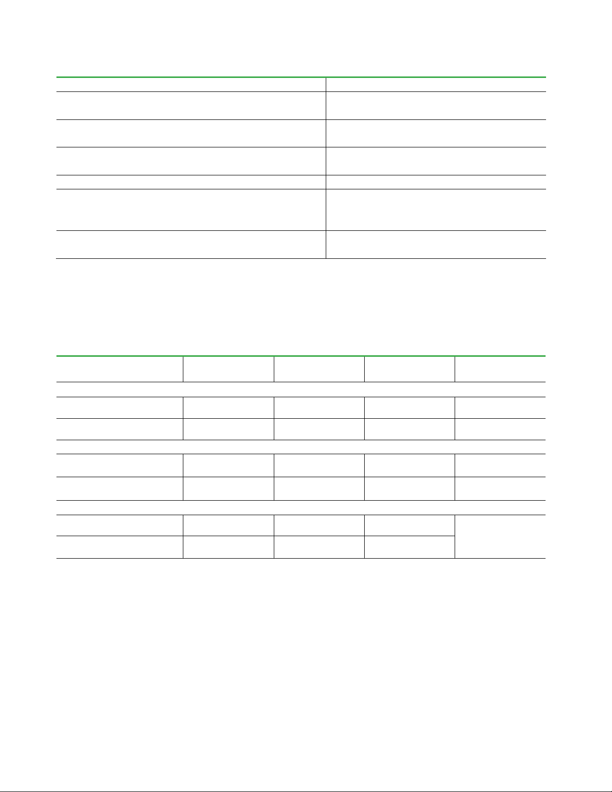
The standard maintenance cleaning and the extended maintenance cleaning is done with the modules submerged in mixed liquor.
The recovery cleaning is done with modules submerged in clean water. Table 9 gives typical concentration and operation ranges
for the different cleaning types.
Table 9. General guidelines for chemical maintenance cleaning
Chemical Typical Concentration
(range)
Typical Soaking Time
(range)
Typical Backwash
Flux
(range)
Typical Fill Volume
(range)
Maintenance Cleaning In-Situ (with mixed liquor in tank)
Sodium Hypochlorite 200 mg/L
(200 - 750 mg/l)
1 hour
(1 - 3 hours)
10 LMH
(5 - 15 LMH)
2 L/m²
(2 - 3 L/m²)
Citric Acid 2000 mg/L
5000 mg/L
1 hour
(1 - 3 hours)
10 LMH
(5 - 15 LMH)
2 L/m²
(2 - 3 L/m²)
Extended Maintenance Cleaning In-Situ (with mixed liquor in tank)
Sodium Hypochlorite 1000 mg/L
(1000 - 2000 mg/l)
6 hours
(6 - 24 hours)
10 LMH
(5 - 15 LMH)
4 L/m²
(4 - 5 L/m²)
Citric Acid 5000 mg/L
(5000 – 10,000 mg/l)
6 hours
(6 - 24 hours)
10 LMH
(5 - 15 LMH)
4 L/m²
(4 - 5 L/m²)
Recovery Cleaning (with clean water in tank or separate tank)
Sodium Hypochlorite
1000 mg/L
(1000 - 2000 mg/l)
8 hours (@30°C)
(8 - 24 hours) - Fill tank min. 5 cm
above the top of the
membranes
Citric Acid
5000 mg/L
(5000 – 10,000 mg/l)
6 hours
(8 - 24 hours)
-

BIO-CEL® EASY | USER MANUAL
MANN+HUMMEL Water & Fluid Solutions | REVISION DATE: 09/06/2021
14
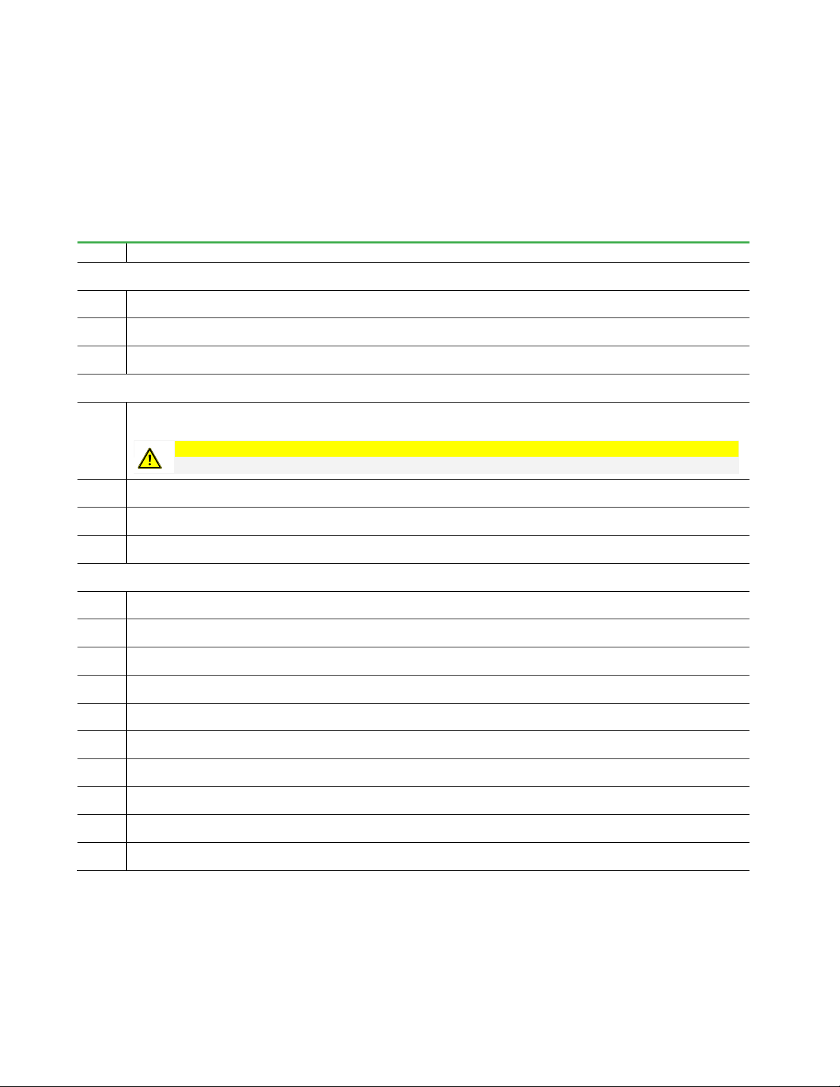
The main steps of the (extended) maintenance cleaning procedure are summarized in Table 10. Please note that this procedure is
the most efficient way for maintenance cleaning whereas less automated systems may use one initial dosing time and a few
additional dosing times.
Table 10. (Extended) Maintenance Cleaning procedure
Step Procedure
1
Stop filtration of filtration line scheduled to be cleaned. Continue to aerate membranes and recirculate mixed liquor for a minimum of 5 minutes.
2
Shut off mixed liquor recirculation pump and isolate membrane tank. Shut off membrane aeration system.
3
Backwash membranes in the train to reach a fill volume of at least 1.5 L/m² while dosing appropriate chemical.
4
Relax membranes to let the chemical soak for a minimum of 5 minutes.
5
Refresh the chemicals by backwashing the membranes in steps of a minimum of 30 seconds while dosing appropriate chemical.
6
Soak membranes for a minimum of 5 minutes.
7
Repeat steps 5 and 6 until the target chemical fill volume and soaking time is reached. It is typical to use a minimum of 6 repetitions to transfer all the
chemical to the membranes.
8
Backwash membranes in the train without adding chemicals to rinse out the chemicals from the piping. The typical rinse volume for the modules is 1
L/m².
9
Open the valves that isolate the membrane tank/line.
10
Turn on the mixed liquor recirculation pump and membrane aeration for a minimum of 5 minutes (minimum of 30 minutes for extended version).
11
Resume normal operation.
Notes:
A pH adjustment to pH 11 during hypochlorite cleaning is not required.
pH monitoring is required for acid cleanings. The pH should be between 2-3 for extended cleans.
pH outside the allowed range of 2-11 may damage the membranes.
BIO-CEL® EASY | USER MANUAL
MANN+HUMMEL Water & Fluid Solutions | REVISION DATE: 09/06/2021
15
In most cases, a recovery clean is performed with sodium hypochlorite and citric acid. Depending on the type of feedwater and the
degree of fouling and scaling, a second chemical clean with sodium hypochlorite after the citric clean may be necessary. The main
steps of the recovery cleaning procedure are summarized below. The following things and materials should be prepared or be
available:
•Compensating reservoir for mixed liquor
•Additional pump for transfer of mixed liquor and draining tank
•Preparation for potential Dewatering Recovery Procedure
Table 11. GENERAL RECOVERY CLEANING PROCEDURE
Step Procedure
Preparing MBR train
1
Stop filtration of membrane train scheduled to be cleaned. Continue to aerate membranes and recirculate mixed liquor for 15 minutes.
2
Shut off mixed liquor recirculation and isolate membrane tank. Shut off membrane aeration system.
3
Drain the membrane tank manually or by using the recirculation pump.
Cleaning MBR tank and modules
4
Perform Dewatering Recovery Cleaning if required to wash out dewatered sludge in-between the sheets. Use a water hose with a “soft” jet (2-3 m/s).
Do not use a strong water jet to clean the modules manually.
Caution
Using a strong water jet may cause membrane delamination.
5
Fill the membrane tank with permeate or water.
6
Aerate membranes for 30 minutes.
7
Drain the membrane tank again to remove all excess sludge removed from membranes.
Performing chemical clean
8
Fill up the membrane tank with water for cleaning to a minimum of 5 cm above the membrane modules.
9 Add chemicals through a separate line directly to the membrane tanks. Start Aeration before adding chemicals; use 5 minutes of air scour at 50%
standard air scour rate to mix the chemicals in the tank.
10 Soak membranes in the cleaning solution. Air scour the modules for 5 minutes every hour to mix and refresh the chemicals in-between the sheets.
11 Drain the cleaning solution and refill with fresh water for the second cleaning solution.
12 Repeat steps 8-11.
13 Open the valves that isolate the membrane tank/train.
14 Turn on membrane aeration and start to recirculate mixed liquor for a minimum of 60 minutes.
15 Continue to recirculate mixed liquor until the membrane tank cleaning volume has been completely replaced.
16 If necessary due to effluent limits, backwash membranes in the train without adding chemicals to rinse out the chemicals in the membranes. The
typical rinse volume for the modules is 1 L/m².
17 Resume normal operation.
Notes:
A pH adjustment to pH 11 during hypochlorite cleaning is not required.
pH monitoring is required for acid cleanings. The pH should be between 2-3.
pH outside the allowed range of 2-11 may damage the membranes.

BIO-CEL® EASY | USER MANUAL
MANN+HUMMEL Water & Fluid Solutions | REVISION DATE: 09/06/2021
16
5Process Design
5.1
BIO-CEL EASY P&ID & FUNCTIONAL DESCRIPTION
Figure 4 shows a simplified P&ID of the MBR process (considering only nitrification as a biological step - pre-treatment and
denitrification is not shown here).
A list of all components and instruments according to the simplified P&ID in Figure 4 is given in Table 12. Please refer to Appendix 1
for the operational sequence chart of the filtration process considering a set-up as given in Figure 4 and a nomenclature as per
Table 12.
Section 4.3 covers some general notes on the main sequences of the filtration process, section 4.4 covers detailed descriptions of
the different cleaning types. However, this section gives more specific information in terms of sequence programming, which
should be used in addition to the operation sequence chart in Appendix 1.
The main standard control strategy is to run the filtration tank in permanent overflow. The recirculation pump P05 is running 3-5
times the permeate flow rate of P04. This assures a constant level in the filtration tank during normal operation and controls the
sludge concentration. The filtration process goes in standby mode once the level in the aeration tank falls below a critical level.
The following modes are recommended to be implemented in the PLC:
SHUTDOWN/OFF
All aggregates are off. This mode is usually used for maintenance purposes. Please note that sludge settling will occur once the
aeration in the filtration is permanently switched off.
STANDBY
Several triggers may cause a tank to go to STANDBY rather than going to SHUTDOWN. These triggers include the following:
-a low aeration tank level,
-a low membrane tank level (in case of malfunction of P05, for instance),
-a loss of compressed air,
-hitting the TMP thresholds.
Figure 4.
Simplified P&ID

BIO-CEL® EASY | USER MANUAL
MANN+HUMMEL Water & Fluid Solutions | REVISION DATE: 09/06/2021
17
In the above cases, the tank will immediately proceed to STANDBY. The permeate pump P04 and recirculation pump P05 ramp
down and Vx1-01 closes. To prevent sludge settling, the blower G02 operates for 5 minutes every 30 minutes.
If the STANDBY triggers no longer exist and a start trigger is active, the tank proceeds into FILTRATION.
FILTRATION
In FILTRATION mode, Vx1-01 is open and the permeate pump P04 is running in the forward direction. Vx4-01 must be closed. The
standard value for the filtration time is 510 seconds. For FILTRATION mode it is mandatory that the blower G02 and the
recirculation pump P05 are running as per designed flow rates. The TMP threshold is -400 mbar. Malfunction of the mentioned
equipment or reaching the TMP threshold will trigger a stop of the filtration process. The plant goes in STANDBY mode in this case.
VENTING
For VENTING, Vx1-01 closes after Vx4-01 is opened and the permeate pump P04 is put into backwash mode. Vx1-01 and Vx4-01
must never be open at the same time, as this would lead to a complete draining of the permeate piping system. The air collected in
the venting tank will be discharged via Vx4-01 from the system. The outgoing pipe can discharge the air/water into the permeate
tank or into the membrane tank. It is required to adjust the venting cycle with regards to frequency and length for the required
flow rates during start-up. The venting tank is usually performed after the first relaxation step.
BACKWASH
As described in section 4.3, the filtration cycle can be operated with or without backwash. If backwash is used, P04 is operated in
the reverse direction at a defined flow rate (corresponding to 10 LMH). In case the TMP hits the threshold of +150 mbar, the plant
goes in STANDBY mode. For BACKWASH, a min level in the permeate tank is required. The standard value for backwash time is 30
seconds.
RELAXATION
In RELAXATION mode, permeate pump P04 is off and Vx1-01 is closed (to prevent any permeation). The blower G02 and the
recirculation pump P05 are still running. The standard value for relaxation time is 30 seconds (if used with backwash in the
filtration cycle) or 60 seconds (if backwash is used only for maintenance cleaning).
(EXTENDED) MAINTENANCE CLEANING
Please refer to section 4.4 for a detailed description of the cleaning procedure. Vx1-01 is open while P04 runs in the reverse
direction. Depending on the chemical to be dosed, Vx2-01 or Vx2-03 is open with P02 or P03 running for chemical dosing.
P03/P02 shall only run if P04 is running. The TMP threshold of +150 mbar applies here as well.
RECOVERY CLEANING
Please refer to section 4.4 for a detailed description of the cleaning procedure. Since the chemicals are dosed into the filtration
tank directly, the chemicals are dosed via Vx2-02 or Vx2-04.

BIO-CEL® EASY | USER MANUAL
MANN+HUMMEL Water & Fluid Solutions | REVISION DATE: 09/06/2021
18
Table 12. Nomenclature of components & instruments of the given P&ID
TAG-# Description Unit
G01
Blower for biology
G02
Blower for membrane tank
P01
Inflow pump to biology (project specific)
P02
Dosing pump for chemicals (alkaline cleaner)
P03
Dosing pump for chemicals (acidic cleaner)
P04
Process permeate pump (reversible for filtration and backwash)
P05
Recirculation pump (in membrane tank, not required if membrane modules are installed in
biology)
P06
Drain pump (removal of excess sludge)
Vx1-01
Permeate header valve to permeate pump (open/closed)
Vx2-01
Valve chemical line (alkaline cleaner) maintenance cleaning
Vx2-02 Valve chemical line (alkaline cleaner) recovery cleaning
Vx2-03 Valve chemical line (acidic cleaner) maintenance cleaning
Vx2-04
Valve chemical line (acidic cleaner) recovery cleaning
Vx4-01
Venting eject valve (open/closed)
Vx4-02
Membrane tank drain valve
Vx4-03
Membrane aeration valve
FI 02-001
Flow control chemical pump P02 l/h (gpm)
FI 03-001
Flow control chemical pump P03 l/h (gpm)
FI 04-006
Flow control sludge draining m³/h (gpd)
FICR 01-001
Flow control recirculation m³/h (gpd)
FICR 04-004
Flow control permeate m³/h (gpd)
FIR 01-001
Flow control process air biology Nm³/h (SCFM)
FIR 04-007
Flow control crossflow aeration Nm³/h (SCFM)
LAL 02-001
Low level alarm B2 (min) -
LAL 03-001
Low level alarm B3 (min) -
LIC 05-001
Level measuring min for P04 (min) meter (feet)
LISA 01-001
Level measuring biology (min and max) meter (feet)
LISA 04-003
Level measuring filter tank (min and max) meter (feet)
PISA 04-008
Pressure sensor for crossflow pipe membrane tank mbar (psi)
PISAR 04-005
Pressure indicator for permeate pipe (overpressure/vacuum) mbar (psi)
QIC 01-001
Oxygen sensor mg/l
QIC 04-001
pH and T sensor - ; °C (°F)
QIC 04-003
MLSS sensor g/l
BIO-CEL® EASY | USER MANUAL
MANN+HUMMEL Water & Fluid Solutions | REVISION DATE: 09/06/2021
19
5.2
EQUIPMENT & TANK DESIGN
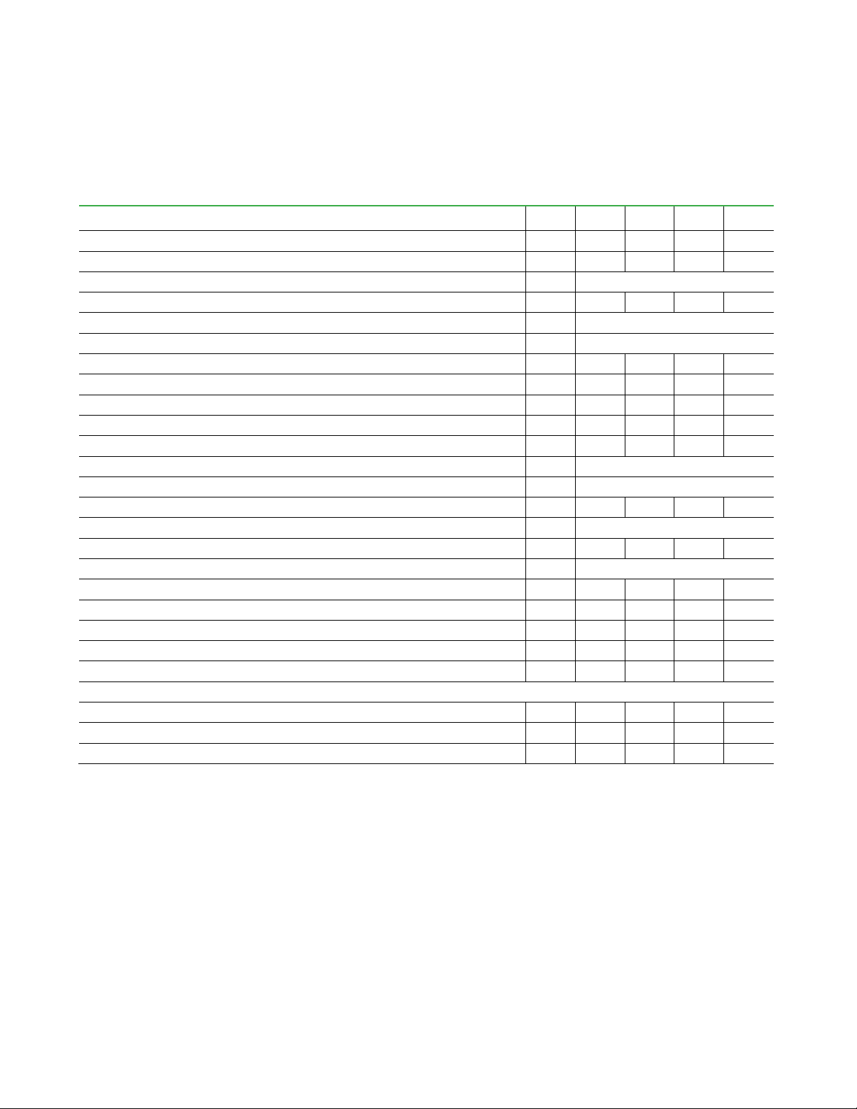
Table 13 shows the most important design parameters with required equipment and tank sizes for different loads of municipal
wastewater. Flow and flux rates are assuming filtration tank influent values as per Table 5.
Table 13. Design parameters, equipment, and tank sizes for different loads of municipal wastewater
Units
100
KLD
75
KLD
50
KLD
25
KLD
Daily Average Flow
m³/d 100 75 50 25
Hourly Peak Flow
m³/h 5,0 3,8 2,5 1,3
Peak Factor
- 1,2
Number of Modules
- 4 3 2 1
Average Flux
l/m2*h 20,8
Average Flow per Module
m³/h 1,0
Recommended Filtration Tank Volume
m35,70 4,60 3,1 1,26
Minimum Water Level
m 1,63 1,63 1,63 1,63
Recommended Width of Tank*
m 1,78 0,99 0,99 0,70
Recommended Length of Tank*
m 1,95 2,82 1,95 1,10
Permeate Pump Reversible + VFD Controlled
m³/h 5,9 4,4 2,9 1,5
Filtration Design Pressure**
mbar + 150
Filtration Design Vacuum Pressure**
mbar - 400
Air Blower for MBR Cross-Flow +VFD Controlled***
Nm³/h 128 96 64 32
Air Blower Design Pressure
mbar 197
Pump for Sludge Recirculation Between MBR Tank and Nitrification
m³/h 19 15 10 5
Venting Unit
l 10
Permeate Tank (min)
m³ 1,0 0,8 0,5 0,5
Chemical Dosing Pump (DP) NaClO
l/h 6,7 5,0 3,3 1,7
Chemical Dosing Pump (DP) Citric Acid
l/h 10 8 5 3
Main Air Collector (SS)
Ø mm 70 60 50 50
Main Permeate
Anoxic Tank Volume Required****
m³ 10 7 5 2
Aeration Tank Volume Required (Using Filtration Tank Volume)****
m³ 20 15 10 5
Estimated Total Airflow Demand for Biology Considering Membrane Aeration****
Nm³/h 99 74 50 25
Notes:
The values above are only a first estimation and for basic engineering of the membrane plant!
*Dimensions are reflecting minimum values, service of modules needs to be done outside the tank.
**This pressure is referring to the transmembrane pressure and does not take local pressure losses in pipes or height
differentials into consideration.
***The capacity of blower has been calculated for the final number of BIO-CEL®EASY modules. The output of the blower must
be regulated based on the number of modules in operation.
****All calculations are based on the German Guideline DWA-A-131 (2016).

BIO-CEL® EASY | USER MANUAL
MANN+HUMMEL Water & Fluid Solutions | REVISION DATE: 09/06/2021
20
Table 14 shows the most important design parameters and required equipment and tank sizes for different loads of industrial
wastewater. Industrial wastewater often shows higher amounts of non-biodegradable substances, which may lead to more fouling.
Flow and flux rates are therefore lower compared to municipal wastewater. However, if the filtration tank influent values are as per
Table 5, flow rates and fluxes of Table 13 can be applied for this application, as well.
Table 14. Design parameters, equipment, and tank sizes for different loads of industrial wastewater
Units
48
KLD
36
KLD
24
KLD
12 KLD
Daily Average Flow
m³/d 48 36 24 12
Hourly Peak Flow
m³/h 2,4 1,8 1,2 0,6
Peak Factor
- 1,2
Number of Modules
- 4 3 2 1
Average Flux
l/m2*h 10
Average Flow per Module
m³/h 0,5
Recommended Filtration Tank Volume
m35,70 4,60 3,1 1,26
Minimum Water Level
m 1,63 1,63 1,63 1,63
Recommended Width of Tank *
m 1,78 0,99 0,99 0,70
Recommended Length of Tank*
m 1,95 2,82 1,95 1,10
Permeate Pump Reversible + VFD Controlled
m³/h 2,8 2,1 1,4 0,7
Filtration Design Pressure**
mbar + 150
Filtration Design Vacuum Pressure**
mbar - 400
Air Blower for MBR Cross-Flow +VFD Controlled***
Nm³/h 128 96 64 32
Air Blower Design Pressure
mbar 197
Pump for Sludge Recirculation Between MBR Tank and Nitrification
m³/h 10 8 5 3
Venting Unit
l 10
Permeate Tank (min)
m³ 0,8 0,5 0,5 0,5
Chemical Dosing Pump (DP) NaOCl
l/h 7 5,0 3,0 2,0
Chemical Dosing Pump (DP) Citric Acid
l/h 14 11 7 4
Main Air Collector (SS)
Ø mm 70 60 50 50
Notes:
The values above are only a first estimation and for basic engineering of the membrane plant!
*
**This pressure is referring to the transmembrane pressure and does not take local pressure losses in pipes or height
differentials into consideration.
***The capacity of blower has been calculated for the final number of BIO-CEL®EASY modules. The output of the blower must
be regulated based on the number of modules in operation.
Venting Unit
The vacuum needed to extract permeate through the membranes also introduces air into the permeate pipes, which must be
expelled. To counteract the tendency for air accumulation, the piping system must only have one high point, and a venting system
must be located at this point. To ensure that the venting system is at the highest point, there should be an incline in the piping
between the venting system and the membranes and a decline in the piping from the venting system to the permeate tank (at a
minimum, the pipes between these points in the system should have no slope at all). See Figure 6.
Table of contents
Other Microdyn Nadir Cleaning Equipment manuals


Popular Cleaning Equipment manuals by other brands


Almeco
Almeco JetBlack Safety Cleaning Booth Installation, operation and maintenance instructions

Sealey
Sealey SM22 instructions

Ryobi
Ryobi EZCLEAN RY3112FB Operator's manual

Ecolab
Ecolab Hybrid 7 Foamatic MA2iM Directions for use

Kärcher
Kärcher K 3.500 manual

Westfalia
Westfalia 92 11 98 Original instructions


