L&R 4000 Series User manual

1
L&R Model 4000 Series
Ultrasonic Cleaning System
Operator's Manual
L&R Manufacturing Company
577 Elm Street
Kearny, NJ 07032-3604
Phone: 201-991-5330 Fax: 201-991-5870
CN 85001 Rev E

2
Contents
Specifications
1.0 Introduction
2.0 Method of Operation
3.0 Installation Instructions
4.0 Operation Instructions
5.0 Operation Warnings & Cautions
6.0 Interconnection Wiring Diagram
7.0 Warranty and Records
WARNING: If the equipment is used in a manner not
specified by the manufacturer the protection provided by
the equipment may be impaired.

3
Specifications - Ultrasonic Cleaning System
* Note Heated Tanks are 50/60 Hz
** Tank to be located in a dry location, 0-35°C, RH 96% Non-Condensing non-corrosive
atmosphere below 2000 M altitude.
*** Do Not position equipment so that it is difficult to operate the disconnecting device.
**** Disconnect unit from mains by unplugging the line cord.
1.0 Introduction
1.1 Your Ultrasonic Cleaning System is easy to operate and install.
Optimum cleaning results will result if certain guidelines are adhered to:
1.1.1 Keep solution level high.
1.1.2 Keep water/soap ratio adequate.
1.1.3 Rinse out tank when "sludge" covers tank bottom.
1.1.4 Read and observe Operation Warnings and Cautions (Section 5.0).
1.2 Please call for information, suggestions or if you have any concerns.
1.3 Please read the entire manual before using system.
MODEL
NUMBER
OVERALL
SIZE
TANK
SIZE WEIGHT SONIC
POWER
Heat
Watts
Heater
Line
Frequency
Heater
Volts
HEATER
Fuse
401206
(HEATED) 19” x 15” x 14” 12” x 6” x 8” 32 4.1w/in2590 W 50/60Hz 117
230
T15.0A/117V
T10.0A/230V
4005 14” x 12” x 14” 12” x 10” x 10” 46 5w/in2N/A N/A N/A
4105
(HEATED) 14” x 12” x 14” 12” x 10” x 10” 46 5w/in2450 W
50/60Hz 117
230
T15.0A/117V
T10.0A/230V
4010 16” x 12” x 16” 16” x 12” x 12” 77 5w/in2N/A N/A N/A
4110
(HEATED) 16” x 12” x 16” 16” x 12” x 12” 77 5w/in2900 W
50/60Hz 117
230
T20.0A/117v
T15.0A/230V
4022 22” x 18” x 20” 20” x 16” x 16” 101 3.8w/in2N/A N/A N/A
4122
(HEATED) 22” x 18” x 20” 20” x 16” x 16” 101 3.8w/in22000 W 50/60Hz 117
230
T30.0A / 117v
T20.0A/230V
4042 26” x 22” x 20” 24” x 20” x 20” 170 3.8w/in2N/A N/A N/A
4142
(HEATED) 26” x 22” x 20” 24” x 20” x 20” 170 3.8w/in24000 W 50/60Hz 230 only T30.0/230V
SS6530
19264 31” x 17” x 11” 30” x 12” x 6” 75 1.7w/in21000 W 50/60Hz
117
T15.0A/117V

4
2.0 Method of Operation
2.1 The ultrasonic cleaner is designed to clean various parts from truck radiators
to rifle barrels using the appropriate cleaning solution.
2.2 The 4002 ultrasonic generator converts line voltage at 50/60 Hz to a suitable high
voltage at 43 KHz that drives the stack transducers mounted on the tank bottom.
The applied High Frequency High voltage causes the transducers to vibrate and in
turn causes cavitation in the solution. As these cavities collapse the dislodge soils on
the object to be cleaned.
2.3 Using the correct solution allows "wetting" of water molecules to dirt/part
molecules for easier separation.
3.0 Installation Instructions
After carefully removing the ultrasonic cleaning system from its' carton and
wood box, remove all packing material and plastic covers and proceed as
follows:
3.1 Place the cleaner on a level surface, allowing for air flow at front and
rear of generator.
3.2 Check drain pipe and plug making sure that they are reasonably tight.
Use Teflon pipe thread sealer when replacing plug or cap.
3.3 Fill tank with recommended L&R solutions or equivalent to approximately two
inches from the top edge of tank. Note that solution displacement, when
submerging part to be cleaned, must be taken into consideration.
3.4 Make sure that the generator’s "Power" switch is off.
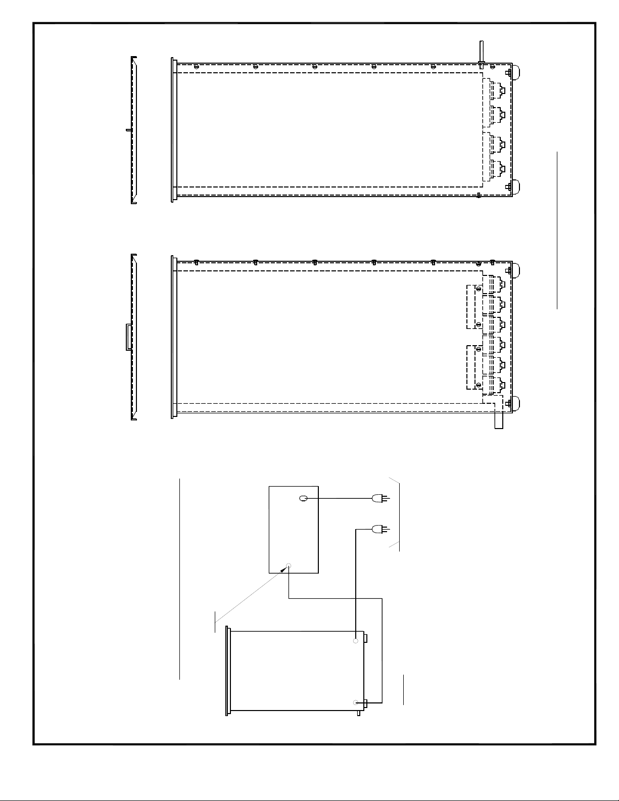
3.5 See Section 6.0 for Interconnection Wiring Diagram. Connect tank ultrasonic
power cable to its connector at rear of generator. Connect Protective Ground
wires if supplied. Make all connections prior to plugging system into the
power lines.
4.0 Operation Instructions
4.1 After filling tank with solution to an appropriate level, place item to be
cleaned in rack or on support and lower into tank. Pieces should be tilted
as needed to allow air bubbles to escape.
4.2 Turn machine on and run for an appropriate time. Usually this will be 5 to
15 minutes. Because cleaning jobs vary, testing will need to be performed
for the particular cleaning task (consult attached sheets for suggestions).
4.3 After item(s) is/are cleaned; remove, rinse off and dry as needed.
4.4 Turn generator off.

5
5.0 Operation Warnings and Cautions
5.1 Ground unit properly. Use only approved grounded power supply.
5.2 Do not operate system without cleaning solution in tank.
5.3 Do not allow solution level to drop below four inches from tank top.
5.4 Do not overfill tank.
5.5 Use recommended L&R solutions or equivalent for best results.
5.6 Allow clearance at sides and rear of generator for air flow.
5.7 Avoid use of flammable solutions such as gasoline, benzene, benzol, etc.
5.8 Connect generator to proper 50/60 Hz socket with third wire ground.
5.9 Always turn unit "off" when not in use.
5.10 Keep tank covered with supplied tank cover.
5.11 Avoid placing hands in the machine.
5.12 Service must be done by competent personnel only.
5.13 Be sure to unplug the machine before moving it.
5.14 Do not subject your machine to shock impact.
5.15 Do not immerse machine in water or any other liquid.
5.16 Do not use acid or bleach in your stainless steel tank as pinholes will be
created.
5.17 Do not use water alone as the carrier bath. A wetting agent, such as L&R
General Purpose Cleaner Concentrate, is required for proper transference
of ultrasonic energy.
Operation Warnings and Cautions!

6
MULTICABLE
TANK & WRAPPER ASSEMBLY
REAR VIEW
3 WIRE POWER RECEPTACLE
TO PROPER GROUNDED
SECOND: CONNECT EACH A.C. POWER CORD
WITH A.C. POWER CABLES DISCONNECTED
TO BNC CONNECTOR AT REAR OF GENERATOR
FIRST: CONNECT TANK ULTRASONIC POWER CABLE
A.C.
CONNECTOR
40KHZ
GENERATOR
TANK
INTERCONNECTION WIRING DIAGRAM

7
Please Record:
Serial # ______________________
Order Date _____________
One Year Limited Warranty
L&R Manufacturing Company warrants this product for a period of one year
from the date of purchase to be free of defects in material and workmanship.
Machine will be repaired free of charge to the customer during the warranty
period.
This warranty does not include damage or product failure resulting from
misuse, abuse or transportation damage. Operating the machine dry is the
most common misuse which results in failure.

8
REVISION HISTORY
C/N 85001
REVISION ECN# DESCRIPTION APPROVED DATE
C 8294 SEE ECN J.P.M. 01/22/2007
D 8316 REVISED SHEET 3,
SEE ECN 8316.
J.P.M. 01/24/2007
E 8725 REVISED SHEET 3
2000 M WAS 2000 Ft
J.P.M. 11/17/2010
This manual suits for next models
10
Table of contents
Other L&R Cleaning Equipment manuals
Popular Cleaning Equipment manuals by other brands

Santoemma
Santoemma Elite-Silent Using and maintenance manual

Sonic
Sonic UW565 Series Operating instructions manual

Thomas
Thomas AQUA FLOOR CLEANER Instructions for use

Omegasonics
Omegasonics RESTORATION PRO 3600PW Operation & instruction manual

djm direct
djm direct VMA915-O instructions

AWH
AWH TANKO CP Series Operating & installation instructions