Microdyn Nadir MICRODYN BIO-CEL XS-1 User manual

Headquarters
MICRODYN-NADIR GmbH
Building D512
Kasteler Straße 45
65203 Wiesbaden
Germany
info@microdyn-nadir.de
www.microdyn-nadir.de
USA Office
MICRODYN-NADIR US, Inc.
93 South La Patera Lane
Goleta, CA 93117
USA
info@microdyn-nadir.com
www.microdyn-nadir.com/en
www.microdyn-nadir.com/trisep
China Office
MICRODYN-NADIR (Xiamen) Co. Ltd.
No. 66 Jinting North Road Xinglin
Xiamen, China 361022
infochi[email protected]om
Singapore Office
MICRODYN-NADIR Singapore Pte. Ltd.
18 Tuas Avenue 8
Singapore 639233
info@microdyn-nadir.com
MICRODYN BIO-CEL XS-1 Pilot Plant Manual // Revision: A // Date: Jul. 25, 2018
Technical Manual
MICRODYN-NADIR
MICRODYN BIO-CEL®XS-1 Pilot Plant
Manual

Table of Contents
2 | 24
MICRODYN BIO-CEL XS-1 Pilot Plant Manual // Revision: A // Date: Jul. 25, 2018
Table of Contents
1About this Document ...............................................................................................4
2Safety & Warning......................................................................................................5
Safety Guidelines.......................................................................................................5
DOs & DON’Ts...........................................................................................................6
General Operational Safety ........................................................................................7
Interim Storage...........................................................................................................7
Transport & Handling..................................................................................................8
Modifications..............................................................................................................9
Commissioning...........................................................................................................9
Operation...................................................................................................................9
Cleaning & Storage Chemicals...................................................................................9
3Product Description MICRODYN BIO-CEL®XS-1..................................................10
Membrane................................................................................................................10
Laminate..................................................................................................................10
Module.....................................................................................................................11
4MICRODYN BIO-CEL®XS-1 Pilot Plant..................................................................12
Equipment................................................................................................................12
Functional Description..............................................................................................13
Connections and Interfaces......................................................................................14
4.3.1 Waste water/ sludge supply..........................................................................14
4.3.2 Clean water supply.......................................................................................14
4.3.3 Permeate discharge.....................................................................................14
4.3.4 Filtration tank overflow .................................................................................14
4.3.5 Surplus sludge.............................................................................................14
4.3.6 Power supply/emergency shutdown .............................................................14
5Installation..............................................................................................................15
6Commissioning ......................................................................................................16
Start-up....................................................................................................................16
Start-up with clean water..........................................................................................16
Start-up with aerated sludge.....................................................................................16
7Operation................................................................................................................17
Operational Sequence and PLC Settings..................................................................17
Cleaning...................................................................................................................22
8Shut-Down and Transport......................................................................................24

Table of Contents
3 | 24
MICRODYN BIO-CEL XS-1 Pilot Plant Manual // Revision: A // Date: Jul. 25, 2018
Figure Index
Figure 1. BIO-CEL XS-1 module............................................................................................10
Figure 2. BIO-CEL Laminate..................................................................................................11
Figure 3. drawing (left) and photo (right) of the pilot plant.......................................................12
Figure 4. Pilot plant and auxiliary equipment..........................................................................13
Figure 5. P&ID of the pilot plant.............................................................................................15
Figure 6: Control Panel –Overview.......................................................................................19
Figure 7: Control Panel - Plant...............................................................................................19
Figure 8: Control Panel –System Control..............................................................................20
Figure 9: Control Panel –Parameters 1.................................................................................20
Figure 10: Control Panel –Parameters 2...............................................................................21
Figure 11: Control Panel –Chart ...........................................................................................21
Table Index
Table 1: NADIR-UP150 properties .........................................................................................10
Table 2: BIO-CEL XS-1 module properties.............................................................................11
Table 3: Overview of equipment.............................................................................................12
Table 4: Overview of operation settings..................................................................................18
Table 5: Maintenance Cleaning procedure*............................................................................22
Table 6: Recovery Cleaning procedure*..................................................................................23

4 | 24
MICRODYN BIO-CEL XS-1 Pilot Plant Manual // Revision: A // Date: Jul. 25, 2018
1 About this Document
This operating manual contains information about the MICRODYN BIO-CEL®XS-1 pilot plant.
The plant is constructed for mobile applications at changing locations. The following chapters
comprise descriptions of the general plant design and the test area aswell as importantoperating
information and safety instructions.
The suitability of the BIO-CEL modules installed in this plant for a special application depends on
the quality of the medium to be filtered, the applied biology and its quality. The suitability also
depends on keeping the directives for the process technology. In general, the BIO-CEL
instruction manual must be considered for the operation of BIO-CEL modules.
All information in this manual corresponds to the actual knowledge of MICRODYN-NADIR. It
should provide an overview of the most important data that are needed to operate the pilot plant.
Please make sure that you always use the up-to-date version of this manual.
MICRODYN-NADIR reserves the right to update data due to new developments. The data given
in this manualcannot betakento claim warranties. MICRODYN-NADIRdoesnot give guarantees
for the performance or life time of the product used in the pilot plant.
MICRODYN-NADIR refuses responsibility for any defects occurring directly and indirectly with
objects or persons if these defects are attributed to improper handling or to not complying with
safety and operating conditions as mentioned in this manual respectively.
The system is property of MICRODYN-NADIR. Improper handling can result in defects of parts
of the plant or the membrane module. Please check the system and the modules regularly by
appropriate tests and measuring. If the filtrate quality worsens, this may be due to several
reasons. Please insure just at the time of start-up that suitable measuring devices for the
detection and prevention of possible defects are available.
Warranty claims are refused for any defects due to improper handling of the modules (see BIO-
CEL manual) or to disregarding the operating parameters given in this operating manual or the
module data sheet.
The leaser takes care of the correct return of the system to MICRODYN-NADIR. At the time of
delivery, the pilot plant is cleaned, and it must be returned also clean. If the plant is not cleaned
before return, all the costs for cleaning will have to be paid by the leaser.
All the components inside the system must be fastened before the transport to prevent sliding or
falling. (Further instructions for the transport see chapter 0.)
Any defects at the pilot plant must be reported to MICRODYN-NADIR immediately. If defects are
not reported, and therefore further defects occur, the emerging costs must be paid by the leaser.
In the case of failure or operation disruption please immediately inform your contact partner or
MICRODYN-NADIR.
5 | 24
MICRODYN BIO-CEL XS-1 Pilot Plant Manual // Revision: A // Date: Jul. 25, 2018
2 Safety & Warning
This operations and maintenance (O&M) manual highlights certain potential hazards related to
handling, operation and maintenance of the equipment. The intent of this chapter is to
supplement any safety and health standards that are applicable to the facility in which the
equipment is being used. The manual does not cover the full spectrum of published safety and
health standards that are mandated by law. Consequently, users should not assume that they
are responsible only forthose standardsreferencedin this manual or thatthose standards quoted
are current. The user of this manual is responsible for ensuring that their own safety program and
operation and maintenance procedures comply with all applicable safety rules, regulations and
standards in accordance with prudent industry standards. In the event that the safety
recommendations in this manual conflict with local safety and health laws, regulations and/or
standards, the user is encouraged to follow the more stringent standard or law.
Safety Guidelines
It is highly recommended to follow the safety guidelines provided in this manual, to comply with
applicable local safety rules, regulationsand standards or to operate andmaintain the equipment
according to prudent industry practices. Failure to follow these safety guidelines, local safety
rules, regulations and standards may result in a potentially hazardous situation. The severity of
the potentially hazardous situations highlighted in this manual have been indicated using the
symbols listed below.
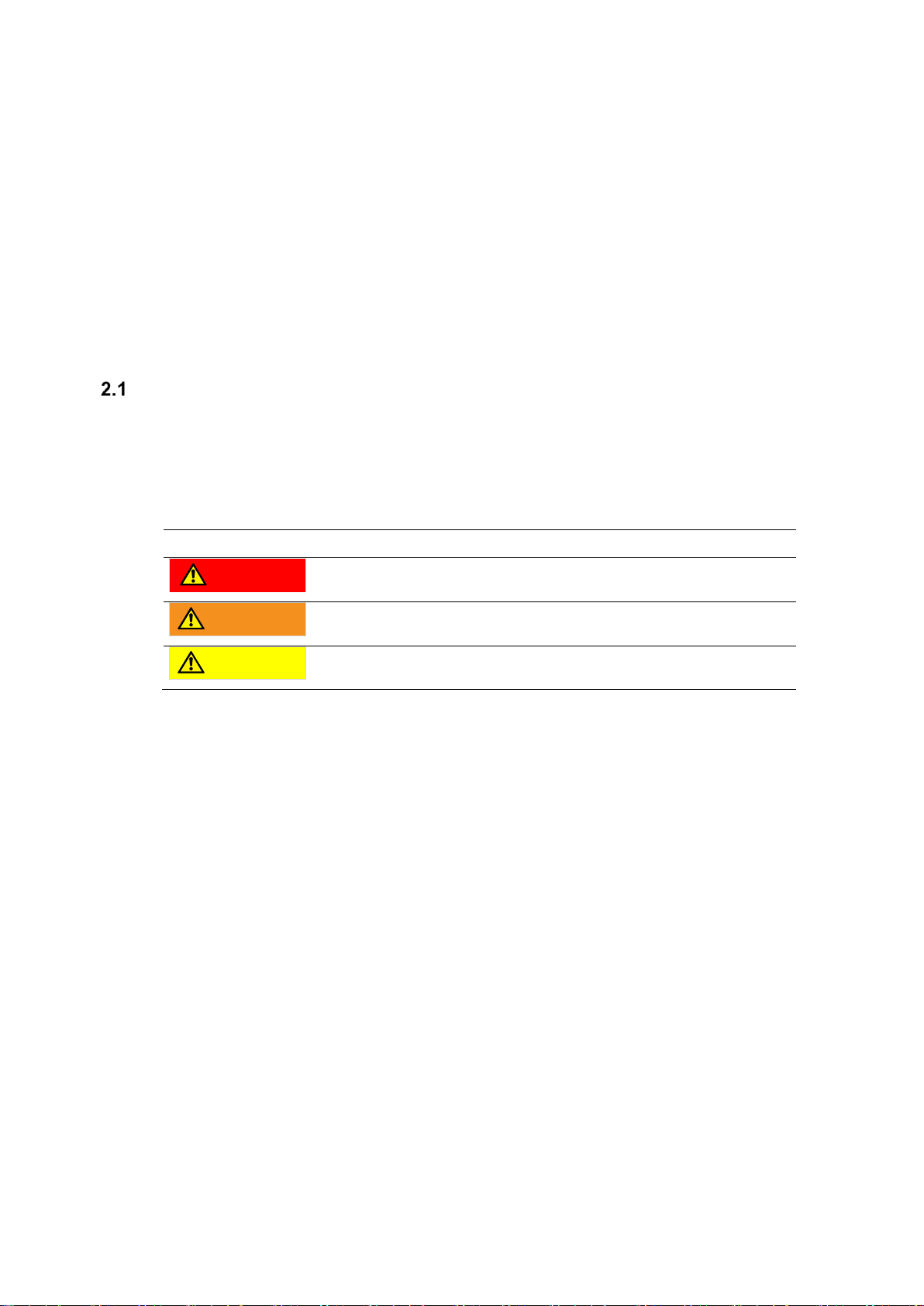
Symbol
Meaning
a
DANGER
DANGER indicates an imminently hazardous situation. If not avoided, it may
result in death, serious injury, or equipment damage.
WARNING
WARNING indicates a potentially hazardous situation. If not avoided, it may
result in death, serious injury, or equipment damage.
CAUTION
CAUTION indicates a potentially hazardous situation. If not avoided, may
result in injury or equipment damage.
DANGER - PRESSURIZED DEVICE: Improper installation, operation or maintenance of the
equipment, including but not limited to the membrane units, electrical system and piping may
result in loss of life, severe bodily injury and/or propertydamage. Please read and understand all
equipment guidelines provided before attempting to open, operate or service the equipment.
Failure to follow these instructions and observe precautions may result in malfunction and
catastrophic failure. Misuse, incorrect assembly or use of damaged or corroded components may
result in serious injury.
WARNING: Certain operating situations require the use of chemicals and other hazardous
substances. Material safety data sheets (MSDS) should be provided by chemical suppliers and
all instructions therein should be adhered to. Safety briefings for the operating personnel should
be carried out by plant health and safety personnel. Always use caution and wear the correct
personal protective equipment (PPE) when handling chemicals.
WARNING: Comply with all pressure and temperaturelimits specified in the technical data sheet
when operating membrane products.
WARNING: The use of chemicals that are not approved or in concentrations higher than those
specified, may cause premature failure of the equipment, including the membrane products.
WARNING: Do not perform any equipment or membrane maintenance unless the system control
power is OFF, the pump starters are OFF, lock out/tag out procedures have been followed and
internal pressure has been relieved from the equipment. Failure to do so may result in serious
injury or death.
WARNING: Do not drink treated water. Treated water is not potable.
CAUTION: The membranes should not be allowed to dry out. The membranes must remain wet
at all times including when the equipment is shut down or for maintenance. Dried out membrane
may result in irreversible membrane damage.

6 | 24
MICRODYN BIO-CEL XS-1 Pilot Plant Manual // Revision: A // Date: Jul. 25, 2018
CAUTION: No anti-foam agents of any kind are to be added into the equipment, without prior
review and written approval from MICRODYN-NADIR. If approved, the anti-foam agents should
only be used in accordance with the conditions specified by MICRODYN-NADIR.
CAUTION: Silicone-based materials, such as waterproofing sprays, lubricating or cutting fluids,
or greases, should not be used in or around the equipment. Using these materials may result in
complete and irreversible membrane fouling.
DOs & DON’Ts
DO –Conduct a site-specific safety review before installation and operation of the equipment.
DO –Install and operate the equipment following the recommendations within this manual.
DO –Familiarize yourself with this entire manual and the equipment, including the controls,
before attempting to operate or perform maintenance on the equipment.
DO –Follow equipment manufacturer recommendations for operation and maintenance.
DO –Wear the appropriate personnel protective equipment.
DO –Routinely inspect for wear and tear on equipment and perform maintenance when
necessary.
DO –Monitor the equipment’s performance and maintain log sheets.
DO –Contact MICRODYN-NADIR with any questions or concerns related to the equipment.
DO –Follow all applicable safety practices and precautions.
DON’T – Install or operate the equipment without knowledge of its operations.
DON’T – Allow unqualified personnel to operate or perform maintenance on the equipment.
DON’T – Allow unsafe conditions: such as water on the floor, worn equipment, exposed wires,
etc.
DON’T – Exceed the mentioned thresholds (i.e. for temperature, pressure, chemical limits) of
the membrane and/or equipment.
DON’T – Use chemicals without prior review and understanding of their MSDS information and
compliance with applicable safety precautions.
DON’T – Use chemicals which have not been approved by MICRODYN-NADIR in writing.
DON’T – Operate the system for purposes other than those described in this manual.
DON’T – Allow the biological processes to perform differently from their intended conditions.
7 | 24
MICRODYN BIO-CEL XS-1 Pilot Plant Manual // Revision: A // Date: Jul. 25, 2018
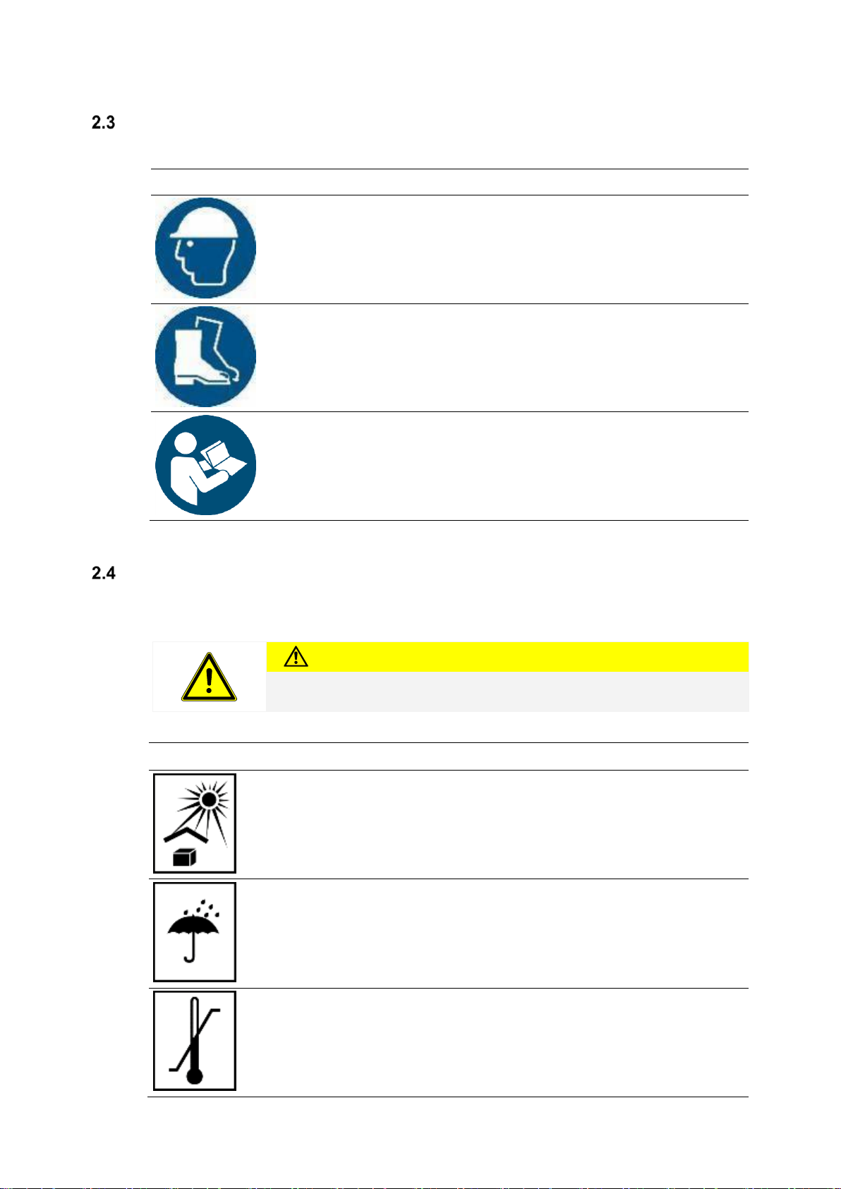
General Operational Safety
Symbol
Instruction
Wear a safety helmet.
Wear safety shoes.
Read the manual before using the product.
Interim Storage
The membrane modules have a shelf life of 12 months when stored according to the conditions
below. More details regarding decommissioning and storage are given in Chapter 8.
Caution
INSTALL THE MEMBRANE MODULE INTO THE TANK DIRECTLY PRIOR TO
WATER COMMISSIONING.
Symbol
Instruction
Do not place the product under direct sunlight.
Do not exceed a humidity of 70 % during storage.
Do not place the product in rain. The membrane is preserved and after the
preservative is washed out, the membrane module should be kept wet at
all times to prevent irreversible damage from drying out.
Store within the following temperature range only: 5-40°C (41-104°F).
Note that this product is not frost-resistant.

8 | 24
MICRODYN BIO-CEL XS-1 Pilot Plant Manual // Revision: A // Date: Jul. 25, 2018
Symbol
Instruction
Always place the product upright unless stated differently in a specific
instruction document.
Handle the product with care. No direct contact with the membrane itself
should occur. Ensure that no damage occurs to the membrane during
transport, assembly and installation. Do not separate the membrane
sheets if they are attached to each other.
Do not damage the outer packaging at the top of the product with knives
or sharp tools. The product must be stored in the delivered packaging till
commissioning is performed.
Transport & Handling
Symbol
Instruction
Only use the eye bolts at the lifting points for elevating the product.
Do not step or stand under a suspended load.
Be cautious of forklift traffic.
The product is top-heavy.
Do not stack the product.

9 | 24
MICRODYN BIO-CEL XS-1 Pilot Plant Manual // Revision: A // Date: Jul. 25, 2018
Modifications
MICRODYN-NADIR must be notified of any modifications to the product or any provided parts.
Commissioning
The commissioning process should be performed by personnel trained by MICRODYN-NADIR
or under the supervision of MICRODYN-NADIR.
Operation
Ensure the proper use of all equipment e.g. pumps, blowers. Contact the manufacturer of these
devices for handling instructions.
The membrane is preserved and after the preservative is washed out, the membrane module
should be kept wet at all times to prevent irreversible damage from drying out.
Cleaning & Storage Chemicals
To safely perform chemical cleanings and safely store chemicals, please follow the instructions
provided bythe chemical manufacturer. The pHrange and maximum concentrationforchemicals
used for cleaning purposes should not exceed the limits of the MICRODYN BIO-CEL®MBR
module as listed on the module data sheet. For further information, please contact the chemical
manufacturer.

10 | 24
MICRODYN BIO-CEL XS-1 Pilot Plant Manual // Revision: A // Date: Jul. 25, 2018
3 Product Description MICRODYN BIO-CEL®XS-1
The MICRODYNBIO-CEL®XS-1 is avery compactmembrane module for pilot testing and small-
scale applications. It combines the membrane unit and the aeration system into one easy to
handle module.
Figure 1. BIO-CEL XS-1 module
Membrane
The membrane used is the NADIR®-UP150, a membrane specifically developed for MBR
applicationsThis membrane has been used for numerous MBR plants worldwide. The membrane
is characterized by an excellent chemical and mechanical durability. It is also hydrophilic, which
allows high flows with a low fouling potential.
Table 1: NADIR-UP150 properties
Material
Nominal pore size
Allowable pH range
Allowable temperature range
Preservative
polyethersulphone (PES)
0.04µm (150 kDa).
2-11
40 °C
Glycerine 20% / Sodium benzoate 3%
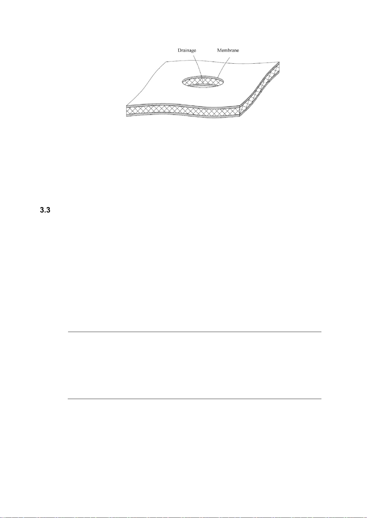
Laminate
The membrane is fused with a drainage layer (polyester) in a lamination process. A solid
connection and at the same time a high water permeability are realized with this process. This
compound creates a backwashable membrane laminate (
Figure 2). This self-supporting membrane laminate with only 2 mm thickness has a high packing
density and a low specific weight.
11 | 24
MICRODYN BIO-CEL XS-1 Pilot Plant Manual // Revision: A // Date: Jul. 25, 2018
Figure 2. BIO-CEL Laminate
Module
The single laminate sheets are combined inthe module. Themodule housing provides protection
for the membranes and mechanical stability. It also helps to direct the cross flow of air and
activated sludge through the laminate sheets.
The membrane modules of the MICRODYN BIO-CEL®XS-1 series are made of polyethylene
(frame), PVC (membrane cassettes and aeration system) and a few parts of stainless steel
(clamping elements). They areresistant to corrosion when used in activated sludge. The aeration
system is integrated in this module and is located at the base of the module. The air is required
in order to generate a small amount of cross flow in the module and on the membrane surface in
order to be able to discharge the sludge out of the module. The pressure differences and the
turbulences created by the air dissolve adhering particles from the membrane surface. The fine-
bubble aerators are made of polyurethane (PUR) with small slit openings to achieve the highest
possible oxygen yield and to prevent sludge penetration even when the modules are in stand-by.
Table 2: BIO-CEL XS-1 module properties
Housing material
Dry weight
Length
Width
Height
Diffuser Material
Nominal membrane area
Polyvinyl chlorides (PVC), Polyethylen (PE)
45kg (99lb)
280mm (0.9ft)
747mm (2.5ft)
1515mm (5.5ft)
Polyurethane (PUR), Polypropylene (PP)
10m² (108ft²)

12 | 24
MICRODYN BIO-CEL XS-1 Pilot Plant Manual // Revision: A // Date: Jul. 25, 2018
4 MICRODYN BIO-CEL®XS-1 Pilot Plant
The pilot plant solely contains the membrane filtration part for separating cleaned waste water
from activated sludge –the main pre-treatment steps (mechanical pre-treatment) is not part of
the pilot plant. You may use the integrated 1 mm inlet screen as a final step of the pre-treatment
or directly guide the pre-treated waste water to the filtration tank. Instructionsfor the construction
of the pre-treatment can be found in the MICRODYN BIO-CEL® Design Guidelines.
Figure 3. drawing (left) and photo (right) of the pilot plant
Equipment
The equipment installed in the pilot plant is listed below. The specifications are equal to the
specifications in the P&ID (Figure 5. P&ID of the pilot plant).
Table 3: Overview of equipment
Specification
Abbreviation
Description
Remark
Membrane
module
1 x BIO-CEL XS-1
10m²
membrane
surface
Tanks
B1
Inlet tank screen
1mm bar screen
B2
Screenings tank
Not on P&ID
B3
Filtration tank
900 L
B4
Permeate tank
35 L
Pumps
P1
Feed pump
(not included in
delivery)
P2
Permeate pump
80 –250 L/h
Blower
G1
Blower for cross flow aeration
Sensors
PICR
Pressure sensor permeate
FICR
Flow meter permeate
LS
Level permeate tank
LSIC
Filling level membrane tank
Schaltschrank
Gebläse
Siebgutkasten
Zulauf-Bogensieb Permeatbehälter
Permeatpumpe
Inlet Screen
Control panel
Blower
Screenings
tank
Permeate
tank
Permeate
pump
13 | 24
MICRODYN BIO-CEL XS-1 Pilot Plant Manual // Revision: A // Date: Jul. 25, 2018
Specification
Abbreviation
Description
Remark
TIR
Temperature aeration tank
TI
Temperature air
PI
Pressure indicator air
FI
Flow indicator air
Valves
V6
Excess sludge outlet / drain
V7
Permeate pipe
V8
Permeate sampling
V9
Permeate pipe
V10
Air pipe
V11
Air pipe
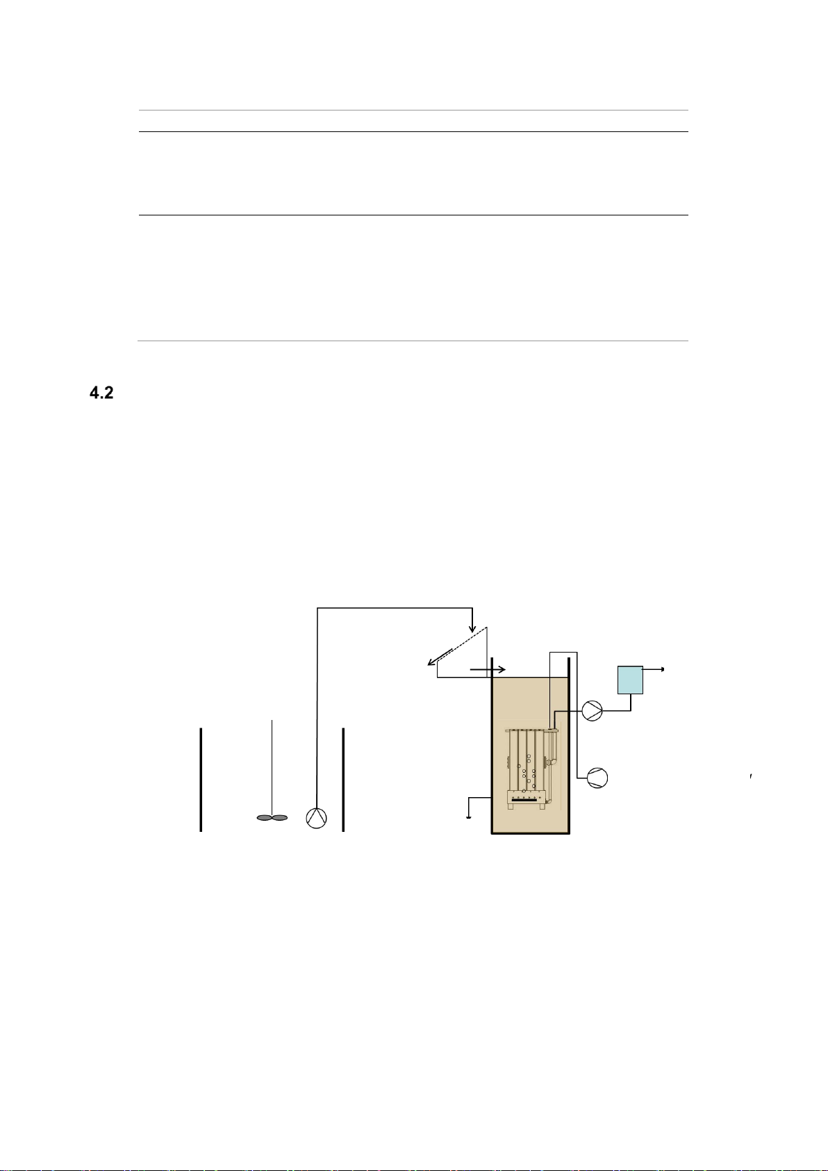
Functional Description
The MICRODYN BIO-CEL®XS-1 pilot plant serves to separate the aerated sludge from cleaned
waste water by means of membrane filtration. The aeration tank of the pilot plant is fed with the
mechanically pre-treated waste water via flexible pipes. Before the effluent reaches the filtration
tank it is flowing through a 1mm bar screen to remove any coarse materials (optional). The
filtration tank is a round tank with an inner diamerter of 75cm and houses the membrane module.
It is possible to operate thefiltration tank with an intermittent denitrification,in this case a separate
anoxic tank for the denitrification is not required.
Figure 4. Pilot plant and auxiliary equipment
The raw waste water is transported into the plant by means of an external pump. Feed supply
and sludge discharge are not part of this plant. They must be provided by the leaser.
The membrane filtration process consists of the steps:
•filtration
•backwashing
•relaxation
•(de-aeration)
Feed line
Feed (aeration) tank
Permeate
tank
Permeate
overflow
Permeate pump
Blower for cross-
flow and aeration
Drain, excess
sludge outlet
Screenings
discharge

14 | 24
MICRODYN BIO-CEL XS-1 Pilot Plant Manual // Revision: A // Date: Jul. 25, 2018
•cleaning
During filtration permeate is sucked through the membranes. After regular and well-defined
periods of time a so-called periodical backwashing is made to keep the membrane surface free
of deposits. In doing so, the permeate pump delivers permeate against the filtration direction.
There is always a relaxation period between the two modes of filtration and backwashing. This
period is called relaxation phase. Usually, in longer, regular time delays the permeate pipe is de-
aerated. Due to the arrangement of the permeate tank, de-aeration is not necessary in this
special case. Cleaning procedures are carried out after definite periods of times to maintain the
membrane permeability. The exact description and the operation principle of the MICRODYN
BIO-CEL®XS-1 modules are to be taken from the BIO-CEL operation and maintenance manual.
The plant is controlled via the integrated touch panel at the switch cabinet. A detailed description
is given in chapter 7.
Connections and Interfaces
4.3.1 Waste water/ sludge supply
The pilot plant may be operated with aerated sludge from a biological cleaning facility (e.g. a
waste water treatment plant) or with raw waste water (after mechanical pre-treatment).
The leaser/operator will use his own pump or feed supply (e.g. by means of controlling the valve
via level differences). The feed pipe from the feed source to the connector at the pilot plant is
supplied by the leaser/operator.
4.3.2 Clean water supply
The MBR pilot plant must be provided with clean water. The leaser/operator has to make sure
that clean water is supplied to the plant, because it is needed for intensive cleaning as well as
for the start-up and shut-down procedures.
4.3.3 Permeate discharge
The cleaned waste water (permeate) is discharged from the plant in free fall.
The drain pipe from its connection to the pilot plant to the suitable terminal reservoir is provided
by the leaser/operator. The proper and professional discharge and disposal has to be warranted
by the operating company.
4.3.4 Filtration tank overflow
The pilot plant is equipped with an emergency overflow of the filtration tank. This overflow must
be connected to the drain or to the waste water feed tank.
4.3.5 Surplus sludge
Surplus sludge is discharged by a manual valve (V6) near the bottom of the filtration tank. The
drain pipe from this connection to a suitable terminal reservoir is provided by the leaser/operator.
The proper and professional discharge and disposal has to be warranted by the operating
company.
4.3.6 Power supply/emergency shutdown
Electric power is supplied via a main high-voltage lead (16A), and an appropriate electrical
connection must be provided by the leaser/operator.
15 | 24
MICRODYN BIO-CEL XS-1 Pilot Plant Manual // Revision: A // Date: Jul. 25, 2018
5 Installation
The installation and adjustment of technical componentsof the MICRODYN BIO-CEL®XS-1 pilot
plant must imperatively be done by expert staff. The pilot plant must be operated by personnel
trained by MICRODYN-NADIR. The operation of the pilot plant mustbe monitored byexpert staff.
The pilot plant must be installed horizontally on a plane surface.
Figure 3 shows a possible setup for system integration of the BIO-CEL XS-1 pilot plant. The
following works needed to be performed before commissioning date:
1. All tanks which are intended to be used for piloting must be cleaned.
2. Connect all auxiliary tanks and pipes according to chapter 4.3.1 - 4.3.5.
3. The membrane module is stored with a preservative solution. Avoid wetting the
membranes until the pilot plant is ready for commissioning. Once wet, the membranes
have to remain submerged in water at all times.
4. Prepare a recent water analysis of the feed water (including at least COD/BOD/NH4-N,
TP and TSS)
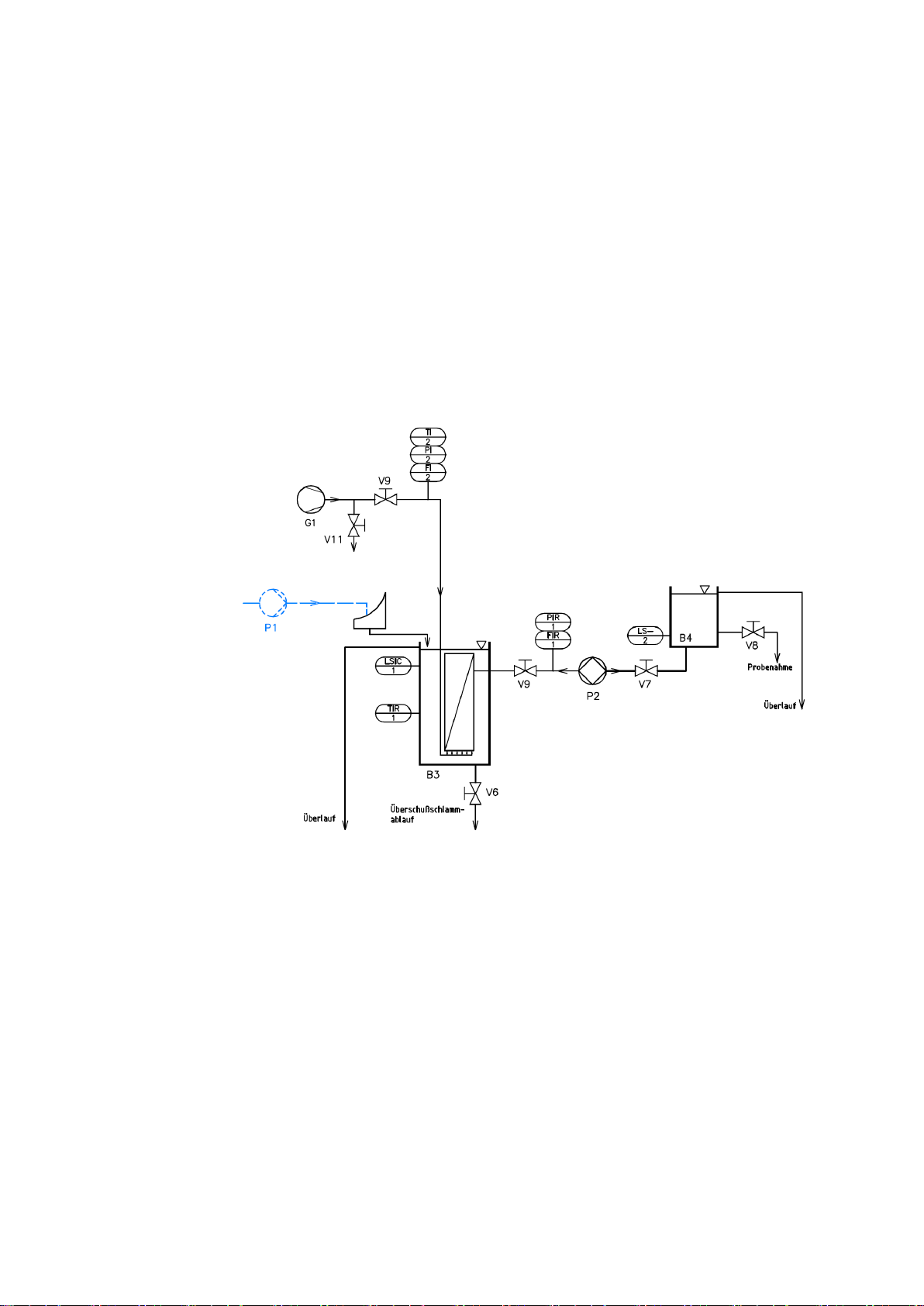
Figure 5.P&ID of the pilot plant

16 | 24
MICRODYN BIO-CEL XS-1 Pilot Plant Manual // Revision: A // Date: Jul. 25, 2018
6 Commissioning
Before the start-up the instructions of the MICRODYN BIO CEL®Operation and Maintenance
manual are to be adhered imperatively. For start-up a supervisor of MICRODYN-NADIR is
recommended onsite.
Start-up
1. Connect electricity
2. Fasten all screw connections of pipes
3. Check, whether the hand valves are easy to move, and control the valve positions
Start-up with clean water
In starting-up with clean water all components are tested with respect to functionality. Leakages
must be eliminated, and program parameters may be corrected.
1. Fill clean water into the filtration tank up to the overflow (in ideal case let the water
overflow continuously).
2. Fill clean water into the permeate tank, permeate piping will be filled as well.
3. Open manual valves V7, V9, V10, V11
4. Switch on panel
5. All electronically controlled actuators/sensorshave to be checked inmanual operation
(see instruction manual for the plant control)
a) Check the pump performance (never run pump with closed V7 and/or V9)
b) Check the blower performance (adjust V10 and V11 in a way to achieve 5-6
Nm3/h air flow)
CAUTION
Air flow to diffuser must not exceed 6 Nm3/h. Too high air flow can cause
irrevocable damage of diffuser.
Notice: In the beginning increased foaming will be noticed, due to the stabilizing agent on the
membranes. Thus, during the start-up procedure, the filtration tank should once be emptied
completely and refilled with water to wash out the stabilizer.
Start-up with aerated sludge
Before the plant can be operated in the automatic mode, all fault messages and the
communication with external components (e.g. with a feed pump) must be checked.
Feed flow and effluent flow must be checked.
The permeate pipe must be de-aerated often during the first filtration cycles, until all air has
passed from the system.
At the beginning of the pilot phase the plant is operated with aerated sludge without sludge
discharge to achieve the designated TSS concentration of about 10-12 g/l as possible fast. The
age of the seed sludge should be at least 5 days.

17 | 24
MICRODYN BIO-CEL XS-1 Pilot Plant Manual // Revision: A // Date: Jul. 25, 2018
7 Operation
TheMICRODYNBIO-CEL®XS-1 module is operated asdeadend filtration, but with air crossflow,
which is induced by a blower. The permeate pump is controlled by the given flow. The cycle of
filtration is:
•Filtration (510 s standard operation)
•Relax 1 (50 s standard operation)
•Back washing (30 s standard operation)
•Relax 2 (10 s standard operation)
The abovelisted intervals arefreely adjustable within acertain range, so that aflexible adaptation
to the operational conditions on site is possible. Plesae note, that usually a regular de-aeration
is necessary for propper function of the filtration stage. Due to the position of the permeate tank,
the permeate system de-aerates trough the tank automatically, so that no separate de-aeration
step is necessary.
For backwashing the conveying direction of the permeate pump is changed. Filtrate from the
permeate tank is pressed into the membrane pockets, reversing the flow and removing the filter
cake and all particles that have entered the membrane pores. In addition to the back washing,
the air crossflow remains on to clear the removed particles off the membrane surface. For this,
the permeate tank must always be filled. The allowable pressure during backwashing is limited
to avoid membrane damage.
An accumulation of air bubbles in the permeate line due to outgassing can occcur, especially
during high transmembrane pressures. To avoid this effect, the permeate tank is situated at the
highes point of the permeate line so the air can easily escape.
The pilot plant runs fully automated after the initial start up.
The power supply of the plant can be interrupted by means of a master switch at the switch
cabinet in the control cabinet.
In emergency cases the plant can be shut down as follows:
Shutdown of the feed pump (P1) and shutdown of the permeate pump (P2) at the control
computer. To switch off the power supply turn the master switch in position “0”.
Operational Sequence and PLC Settings
The operation sequence starts with filling the filtration tank with waste water. Thefilling sequence
is triggered by thelevel sensor in the filtration tank.Filling ends when the max level inthe filtration
tank is reached and starts again when the min level is reached.
The next step is the denitrification phase (if required). During this phase, the aeration is mainly
switched off to maintain anoxic conditions in the filtration tank. The blower is only running for
short amounts of time to ensure the sludge is properly mixed. The duration of the denitrification
phase iscontrolledby a timer and can be adjusted tomatch the local requirements, if notrequired
set TDN to 0.
master switch

18 | 24
MICRODYN BIO-CEL XS-1 Pilot Plant Manual // Revision: A // Date: Jul. 25, 2018
After the denitrification follows the filtration. To start this phase, there is a pre-aeration cycle to
get the sludge mixed. The pre-aeration also serves as an initial cleaning of the membrane
surface. The duration of the pre-aeration is adjustable.
Next comes the filtration, which consist of 4 steps (filtration, relaxation 1, back washing and
relaxation 2), as mentionend previously. During filtration the level inside the filtration tank will go
down. Filtration will continue until the level hits the min level. Once this happens the operation
sequence starts anew with the filling sequence.
The operation sequence as well as the recommended settings are descibed in Table 4: Overview
of operation settings.
Table 4: Overview of operation settings
Operation step
Description
Settings
Recommended
Filling of the
aeration tank (FILL)
Feed pump starts at Lmin and
stopps at Lmax
Blower off
LMIN = 150 –160 cm
LMAX = 165 –175 cm
LMIN = 155 cm
LMAX = 170 cm
Denitrification (DN)
Denitrification with intermittent
aeration for sludge mixing
TDN = 0 - 99 min
TDN = 30 min
Intervall between the aeration
times
Blower off
TDN,DELAY = 0-99 min
TDN,DELAY = 10
min
Aeration for sludge mixing
Blower on
TDN,MIX = 0-99 sec
TDN,MIX = 10 sec
Filtration (FN)
Pre-aeration to make sure the
sludge is well aerated and
mixed
Blower on
TPRE = 0-99 min
TPRE = 10 min
Filtration, Permeate pump is
running
Blower on
TFILT = 0-999 sec
QFILT = 80-250 L/h
TFILT = 510 sec
QFILT = 130 L/h
Relax 1
Back wash (Permeate pump
running in reverse)
Relax 2
Blower on
TR1 = 0-999 sec
TBW = 0-999 sec
QBW = 80 –500 L/h
TR2 = 0-999 sec
TR1 = 50 sec
TBW = 30 sec
QBW = 130 L/h
TR2 = 10 sec
There are start and stop ramps for the permeate pump to avoid sudden pressure shocks in the
system. These rams are pre-set and cannot be changed. The ramping time is set to TRAMP = 5
sec. The up ramp is always part of the pump interval, the down ramp is part of the following
interval.
Example:The permeate pumpis set to runfor 510 sec.,followed by 50 sec. relaxation. Theactual
runtime will be 5 sec. ramping up, 505 sec. running at target flow, 5 sec. ramping down followed
by 45 sec. relaxation.
Figure 6 to 11 show the control panel graphics to navigate trough the PLC settings.

19 | 24
MICRODYN BIO-CEL XS-1 Pilot Plant Manual // Revision: A // Date: Jul. 25, 2018
Figure 6: Control Panel –Overview
Figure 7: Control Panel - Plant

20 | 24
MICRODYN BIO-CEL XS-1 Pilot Plant Manual // Revision: A // Date: Jul. 25, 2018
Figure 8: Control Panel –System Control
Figure 9: Control Panel –Parameters 1
Table of contents
Other Microdyn Nadir Cleaning Equipment manuals


Popular Cleaning Equipment manuals by other brands

WOLFF
WOLFF Cleanfox 7.5 Use and maintenance

Omegasonics
Omegasonics RESTORATION PRO 3600PW Operation & instruction manual

Kärcher
Kärcher K 4.94 M manual

Matrix Cleaning Systems
Matrix Cleaning Systems 4x4SD10KW User instructions

Uzin Utz
Uzin Utz WOLFF 168801 Translation of original operating manual

MS Schippers
MS Schippers MS Greenline 0809889 Operation manual


