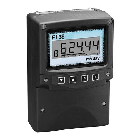
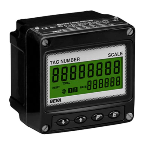
BEKA BA354D User manual

Issue: 5
16th September 2008
BA354D
Intrinsically safe
4/20mA loop-powered
field mounting
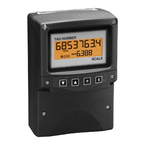
rate totaliser
issue 5

2
1. Description
2. Operation
2.1 Controls
2.2 Displays
3. Intrinsic Safety Certification
3.1 ATEX certificate
3.2 4/20mA input
3.3 Reset terminals
3.4 Zones, gas groups & T rating
3.5 Certification label information
4. System Design for Hazardous Areas
ATEX certification
4.1 Flow transmitter loops
4.2 Remote indication
4.3 Resetting the total display to zero
5. Installation
5.1 Location
5.2 Installation procedure
5.3 EMC
6. Programming and Calibration
6.1 Calibration structure
6.2 Accessing programme functions
6.3 Summary of programmable
functions.
6.4 Root extractor
6.5 Resolution
6.6 Position of the decimal points
6.7 Calibration of rate display using an
external current source.
6.8 Calibration of rate display using
internal references.
6.9 Conditioning sub-menu
6.9.1 AC rejection
6.9.2 Calibration of internal
references.
6.10 Resetting grand total
6.11 Timebase
6.12 Function of the Ppush-button
6.13 Total scale factor
6.14 Percentage clip-off
6.15 Local reset of total display
6.16 Security code
6.17 Over and under-range
7. Calibration Examples
7.1 Using an external current source
7.2 Using the internal references
8. Maintenance
8.1 Fault finding during commissioning
8.2 Fault finding after commissioning
8.3 Servicing
8.4 Routine maintenance
8.5 Guarantee
8.6 Customer comments
9. Accessories
9.1 Units of measurement and
instrument identification.
9.2 Alarms
9.2.1 Solid state output
9.2.2 Intrinsic safety
9.2.3 Programming and
adjustment
9.2.4 Alarm enable
9.2.5 Type of alarm
9.2.6 Setpoint adjustment
9.2.7 Alarm function
9.2.8 Alarm output status
9.2.9 Hysteresis
9.2.10 Alarm delay
9.2.11 Alarm silence time
9.2.12 Access setpoint
9.2.13 Adjusting alarm setpoints
from display mode.
9.3 Display backlight
9.4 External push-buttons
9.5 Pipe mounting kits
9.6 Stem mounting kit
10. Index
Appendix 1
ATEX dust certification
CONTENTS
The BA354D is CE marked to show compliance with the
European Explosive Atmospheres Directive 94/9/EC
and the European EMC Directive 2004/108/EC

3
1. DESCRIPTION
The BA354D is an intrinsically safe 4/20mA loop-
powered rate totaliser primarily intended for use
with flowmeters. The instrument simultaneously
displays the rate of flow and the total flow in
engineering units on two separate displays. The
BA354D only introduces a 1.1V drop which allows
it to be installed into almost any 4/20mA flow loop.
No additional power supply or battery is required.
The BA354D has been certified intrinsically safe by
European Notified Body Intertek Testing Sevices
(ITS) to the ATEX Directive 94/9/EC for use in
explosive gas and combustible dust atmospheres.
The EC-Type Examination Certificate specifies that
under fault conditions the voltage, current and
power at input terminals 1 and 3 will not exceed
those specified for simple apparatus in Clause 5.4
of EN50020:1994.
ATEX dust certification is an option – See
Appendix 1.
Housed in a robust IP66 glass reinforced polyester
(GRP) enclosure with an armoured glass window,
the BA354D is surface mounting, or may be pipe
mounted using one of the accessory kits. A stem
mounting kit is also available allowing direct
mounting onto a flowmeter conduit entry.
2. OPERATION
Fig 1 shows a simplified block diagram of a
BA354D. The 4/20mA input current flows through
resistor R1 and forward biased diode D1. The
voltage developed across D1, which is relatively
constant, is multiplied by a switch mode power
supply and used to power the instrument. The
voltage developed across R1, which is proportional
to the 4/20mA input current, provides the input
signal for the analogue to digital converter.
Each time a 4/20mA current is applied to the
instrument, initialisation is performed. After a short
delay the following display sequence occurs:
All segments of the display are activated for
about 3 seconds.
Decimal points on large display are
sequentially activated for about 3
seconds.
Rate display and totaliser start to
function using calibration information
stored in the instrument's permanent
memory.
If the 4/20mA current is disconnected during
operation the latest total and grand total are stored
in permanent memory.
Fig 1 Simplified block diagram of BA354D
2.1 Controls
The BA354D is controlled and calibrated via four
push-button switches which are located behind the
instrument control cover, or as an option on the
outside of the instrument cover. In the operating
mode i.e. when the instrument is displaying rate
and total flow the switch functions are:
Summary of Switch Functions
PDisplays input current in mA or as a
percentage of span.
Down Shows rate display calibration at 4mA
input
Up Shows rate display calibration at
20mA input
E+Down Grand total –
displays least significant 8 digits
E+Up Grand total –
displays most significant 8 digits.
Down Resets total display
+Up programmable function
Note: When optional alarms are fitted the push-
buttons may be programmed to have alternative
functions – see section 9.2

4
Full Description of Switch Functions
PWhile this button is pushed the rate
display will show the input current in
mA, or as a percentage of the
instrument span depending upon how
the instrument has been programmed.
When the button is released the normal
display in engineering units will return.
The function of this push-button may be
modified when alarms are fitted to the
instrument.
Down While this button is pushed the
instrument will show the calibrated rate
display with 4mA input - usually zero for
flow applications. When the button is
released the flow rate will again be
displayed.
Up While this button is pushed the
instrument will show the calibrated rate
display with 20mA input. When the
button is released the flow rate will
again be displayed.
E+ Down While these buttons are pushed the
total display will show the least
significant eight digits of the grand total,
and the grand total annunciator will be
activated.
E+Up While these two buttons are pushed the
total display will show the most
significant eight digits of the grand total
and the grand total annunciator will be
activated.
Down Resets the total display to zero
+Up when these two push-buttons are
operated simultaneously.
Selectable function from programme
menu.
See section 6.15
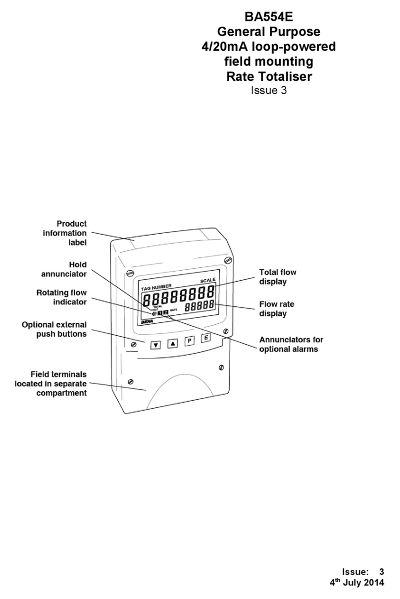
2.2 Displays
The BA354D has two digital displays and
associated annunciators, plus a flow indicator as
shown on page 1.
Rate Shows the flow rate on the smaller
Display five digit display.
Total Shows the total flow on the larger
display eight digit display. Is set to zero when
reset is operated.
Flow This disc in the lower left hand
indicator corner of the display 'rotates' when the
input current exceeds 4mA.
INTRINSIC SAFETY CERTIFICATION
3.1 ATEX certificate
The BA354D has been issued with an EC-Type
Examination Certificate by Notified Body ITS
Intertek Testing and Certification confirming
compliance with the European ATEX Directive
94/9/EC for Group II, Category 1, gas and dust
atmospheres, EEx ia IIC T5. The instrument
bears the Community Mark and, subject to local
codes of practice, may be installed in any of the
European Economic Area (EEA) member
countries. ATEX certificates are also acceptable
for installations in Switzerland.
This manual describes installations in explosive
gas atmospheres which conform with BS
EN60079:Part14:2003 Electrical Installation in
Hazardous Areas. When designing systems for
installation outside the UK, the local Code of
Practice should be consulted.
For the use in the presence of combustible dust,
please refer to Appendix 1 which describes
installations complying with BS EN 50281-1-
2:1999. Please note that dust certification is an
option which must be specified when the
instrument is ordered.
3.2 4/20mA input
In Europe, sources of energy which do not
generate more than 1.5V; 100mA and 25mW are,
for intrinsic safety purposes, considered to be
simple apparatus (Clause 5.4 of EN50 020:1994).
Although the BA354D indicator does not itself
comply with the requirements for simple apparatus,
the EC-Type Examination Certificate specifies that
under fault conditions the voltage, current and
power at the 4/20mA input terminals 1 and 3 will
not exceed those specified for simple apparatus in
Clause 5.4 of EN50020:1994. This allows the
BA354D 4/20mA input terminals to be connected
into any intrinsically safe circuit protected by a
Zener barrier or galvanic isolator without the need
for additional certification, providing the output
parameters of the circuit do not exceed:
Uo 30V dc
Io 200mA dc
Po 0.85W
The BA354D EC-Type Examination Certificate
specifies that the maximum equivalent capacitance
and inductance between the two 4/20mA input
terminals 1 and 3 is:
Ci 20nF
Li 10µH
5
To determine the maximum permissible cable
parameters these figures must be subtracted from
the maximum cable capacitance and inductance
permitted by the system certificate of the loop into
which the BA354D is connected.
3.3 Reset terminals
The BA354D total display may be reset to zero by
connecting the reset terminals RS1 and RS2
together. These two terminals have the following
output and input safety parameters:
Uo 5V dc
Io 1.3mA dc
Po 1.6mW
Ui 28V dc
Ii 98mA dc
Pi 0.65W
The maximum equivalent capacitance and
inductance between them is:
Ci 1.2nF
Li 0µH
The total display may be reset to zero from within
the hazardous area by any mechanically operated
switch connected directly to terminals RS1 and
RS2. Alternatively, the BA354D may be
programmed so that the total display is reset to
zero when the Up and Down push-buttons are
operated simultaneously.
To reset the total display from the safe area a
Zener barrier or intrinsically safe relay is required
to transfer the contact closure into the hazardous
area. The BA354D system certificates define
suitable interface devices together with the
maximum permissible cable parameters. Almost
any intrinsically safe relay with certification
permitting the contacts to be connected to
equipment in the hazardous area may be used.
Alternatively, one of the positive diode return Zener
barriers listed in the system certificate may be
used - see Fig 3A.
3.4 Zones, gas groups and T rating
The BA354D has been issued with an EC Type
Examination certificate confirming that it complies
with the requirements for Group II Category 1 G
EEx ia IIC T5 (Tamb –40 to 60oC) specified in the
ATEX Directive. When connected to a suitable
system the BA354D may be installed in:
Zone 0 explosive gas air mixture
continuously present.
Zone 1 explosive gas air mixture
Likely to occur in normal
operation.
Zone 2 explosive gas air mixture not
likely to occur, and if it does will
only exist for a short time.
Be used with gases in groups:
Group A propane
Group B ethylene
Group C hydrogen
Having a temperature classification of:
T1 450°C
T2 300°C
T3 200°C
T4 135°C
T5 100°C
At an ambient temperature between –40 and
+60°C.
Note: the guaranteed operating temperature range
is –20 to +60°C
This allows the BA354D to be installed in all Zones
and to be used with most common industrial
gases.
3.5 Certification Label Information
The certification label is fitted in a recess on the
top outer surface of the enclosure. It shows the
ATEX certification information plus BEKA
associates’ name and location. Non European
certification information may also be included. The
instrument serial number and date of manufacture
are recorded on a separate label inside the
terminal compartment.

6
4. SYSTEM DESIGN FOR HAZARDOUS AREA
4.1 Flow transmitter loops
A BA354D rate totaliser may be connected in
series with almost any intrinsically safe 4/20mA
flow loop and calibrated to display the rate of flow
and total flow. There are two basic design
requirements:
1. The intrinsic safety output parameters of the
4/20mA loop, which are defined by the Zener
barrier or galvanic isolator, must be less
than:
Uo 30V dc
Io 200mA dc
Po 0.85W
2. The loop must be able to tolerate the
additional 1.1V required to operate the
indicator.
Fig 2 illustrates an application in which a BA354D
indicator is connected in series with a 2-wire flow
transmitter protected by a Zener barrier.
Fig 2 BA354D in a flow loop
4.2 Remote indication
A BA354D may be driven via an intrinsically safe
interface from a 4/20mA safe area signal to
provide a remote indication of rate and total flow
within a hazardous area. The type of interface is
not critical, either a Zener barrier or a galvanic
isolator may be used, providing that Uo, Io and Po
are not exceeded.
If one side of the 4/20mA current loop may be
earthed, a single channel Zener barrier provides
the lowest cost protection. If the 4/20mA signal is
not isolated, then two Zener barriers, a two
channel Zener barrier or a galvanic isolator must
be used.
When the hazard is a IIC gas, and two single
channel Zener barriers or a two channel Zener
barrier are used, only one barrier or channel may
be a 28V 300ohm device. A 10V 50Ωor diode
return barrier may be used for the second channel
to form a safe combination.
Again it is necessary to ensure that the voltage
capability of the 4/20mA signal is sufficient to drive
the indicator plus the voltage drop introduced by
the intrinsically safe interface. Figs 3A, 3B and 3C
show the alternative circuits which may be used.
Fig 3A Simplest circuit with one side of
20mA current loop connected to
earth.
Also shows optional resetting from
safe area.

7
Fig 3B Two Zener barrier channels are
required if the 4/20mA current loop
can't be earthed at the barrier
busbar.
Also shows optional resetting from
hazardous area
Fig 3C Galvanic isolator can be used with any
4/20mA current loop.
4.3 Resetting the total display to zero
The BA354D may be programmed to reset the
total display to zero when the Up and Down
buttons are pushed simultaneously for 2 seconds,
or an external switch located in the safe or the
hazardous area may be used. Fig 3A illustrates
how the total display may be reset from the safe
area via a single channel diode return Zener
barrier. A certified intrinsically safe relay or
certified opto-isolator may also be used.
Fig 3B shows how the total display may be reset to
zero by an external switch in the hazardous area.
The switch must be mechanically operated and
able to withstand a 500V dc insulation test, but no
Zener barrier or galvanic isolator is required.

8
5. INSTALLATION
5.1 Location
The BA354D rate totaliser is housed in a robust
IP66 glass reinforced polyester (GRP) enclosure
incorporating an armoured glass window and
stainless steel fittings. It is suitable for exterior
mounting in most industrial environments,
including off-shore and waste water treatment.
Please consult BEKA associates if high vibration is
anticipated.
The BA354D enclosure is surface mounting.
Accessory kits described in sections 9.5 & 9.6 of
this manual enable the instrument to be mounted
onto a vertical or horizontal pipe, or directly onto a
flowmeter conduit entry.
The field terminals and the two mounting holes are
located in a separate compartment with a sealed
cover allowing the instrument to be installed
without exposing the display assembly.
Terminals 2 and 4 are internally joined and may be
used for linking the return 4/20mA wire - see Fig 2.
Similarly terminals 5 and 6 are internally joined and
may be used for linking the cable screens. The
BA354D earth terminal is connected to the internal
EMC filters. For maximum radio frequency
interference rejection this terminal should be
connected to a local earth, or to a cable screen
which is earthed in the safe area. To prevent
circulating currents, cable screens should only be
earthed at one point in the safe area.
The BA354D enclosure is supplied with a bonding
plate to ensure electrical continuity between the
three conduit / cable entries.
5.2 Installation Procedure
Fig 4 illustrates the instrument installation
procedure.
a. Remove the instrument terminal cover by
unscrewing the two captive 'A' screws.
b. Mount the instrument on a flat surface and
secure with two M6 screws through the 'B'
holes. Alternatively use one of the mounting
kits described in section 9.5
c. Remove the temporary dust seals from the
three cable entries and install the required
glands, conduit fittings or blanking plugs.
Note: the temporary dust seals do not
provide IP66 protection.
d. Connect the field wiring to the terminals as
shown in Fig 5.
e. Replace the instrument terminal cover and
evenly tighten the two 'A' screws.
Fig 4 BA354D installation procedure
5.3 EMC
The BA354D complies with the requirements of
the European EMC Directive 2004/108/EEC. For
specified immunity all wiring should be in
screened twisted pairs, with the screens earthed
in the safe area.
Additional immunity may be obtained by
connecting the BA354D earth terminal to a local
earth, or to a cable screen which is earthed in the
safe area. If this terminal is not connected,
personal and intrinsic safety will not be degraded.

9
Fig 5 Dimensions and terminal connections

10
6. PROGRAMMING & CALIBRATION
The BA354D is programmed and calibrated via
four push-buttons which are located behind the
instrument control cover. If frequent access to
the push-buttons is required, the rate totaliser can
be supplied with duplicate membrane push-buttons
mounted on the outside of the control cover.
All the programming functions are contained in an
easy to use menu which is shown diagramatically
in Figs 7A and 7B. Each function is summarised
in section 6.3 which includes references to more
detailed information. Although this simple menu
driven system enables most adjustments to be
made without repeated reference to this manual, it
is recommended that at least the summary of the
programmable functions in section 6.3 is read
before attempting programming or recalibration.
When the instrument is fitted with alarms, the basic
menu is expanded to include the alarm functions
that are described in section 9.2 of this manual.
Note: While the instrument is being programmed
or calibrated totalisation is suspended, any flow
occurring during this time will not be recorded.
6.1 Calibration structure
Fig 6 shows the BA354D calibration structure. The
4/20mA input current, which in flow applications
represents flow rate, is displayed on the five digit
rate display. Using the instrument 'CAL' or 'SEt'
functions this display may be calibrated to show
the flow rate in engineering units. Both the zero
(display at 4mA) and the span (display at 20mA)
are adjustable, although for flow application the
display at 4mA is usually zero. The position of
the decimal point in the rate display is defined by
the d.p. function. To simplify calibration the
BA354D uses floating point arithmetic, moving the
rate display decimal point position will therefore
affect totalisation.
Fig 6 Calibration structure
The BA354D total display is calculated from the
rate display using two serial factors: the timebase
't-bASE' and the total scaling factor 'SCALE-t'.
The timebase divides the rate display according to
whether the rate display represents flow per
second, per minute or per hour. The total scaling
factor 'SCALE-t' is a wide range programmable
dividing factor allowing the rate and total displays
to be in different units.

11
For example, if a BA354D is displaying rate in litres
per minute, setting 'SCALE-t' to 4.5461 produces a
total display in UK gallons. Alternatively, setting
'SCALE-t' to 4546.1 will produce a total display in
thousands of UK gallons.
The total is calculated and the display updated
twice per second, which defines the resolution of
the total flow display. When total alarms are used
for batching applications, this resolution may
define the accuracy of the system.
6.2 Accessing programming functions
Throughout this manual push-buttons are shown in
italics e.g. P or Up push-button, and legends
displayed by the instrument are shown within
inverted commas e.g. 'CAL' and ' ALr2'.
Access to the programme menu is obtained by
operating the Pand Epush-buttons
simultaneously. If the instrument is not protected
by a security code the first parameter 'root' will be
displayed. If a security code other than the default
code 0000 has already been entered, the
instrument will display 'COdE'. Press Pto clear
this prompt and enter the security code for the
instrument using the Up or Down push-button
adjust each digit, and the P push-button to move
control to the next digit. If the correct code has
been entered pressing Ewill cause the first
parameter 'root' to be displayed. If an incorrect
code is entered, or a push-button is not operated,
the instrument will timeout after ten seconds and
automatically return to the display mode.
Apart from defining the position of the decimal
point in the rate display all programme functions
and prompts are shown on the large eight digit
display.
Once within the main programme menu the
required parameter can be reached by scrolling
through the menu using the Up and Down push-
buttons as shown by the programme structure in
Figs 7A and 7B. When returning to the operating
mode following recalibration or changes to any
parameters, the total display will show circulating
decimal points for a few seconds while the new
information is stored in permanent memory.
All new BA354D are supplied calibrated as
requested at the time of ordering. If calibration
information is not supplied, the BA354D will be set
to display a rate of 0.00 with 4mA input and 100.00
with 20mA input. The total scale factor will be set
to 1 with a timebase of seconds.

12
CLr.YES
t-bASE C--P
4-20 00000 00 OFF
LOC-rSET
0000
COdE
When fitted alarms
appear here
Clear
grand total
or
to select
CLr-YES
confirmed by
entering
WARNING
Cleared grand
total can not
be recovered
Timebase
or
between
4-20mA and
to toggle
or
Function of
P button
% of span to next digit.
Total scale
to adjust value
Press or
and to move
factor
Press +
to position
decimal point
% clip-off
to adjust value
Press or
between
0 and 10% or
and
pressing
Define Security
Enter by
Code
to move to
next digit
Local reset
or
Fig 7B. Programme Structure
CLr.Gtot
EEEEEEE
EPPEPE
PE PE PEPE
PP
To Cond
function on
Fig 7A
SurE
P E
SurE using
or
to adjust
display and
to move
to next digit
P
CLIP-OFF
SCALE-t
tb-1
to define rate
display timebase
select
tb-1 for flow/sec
tb-60 for flow/min
tb-3600 for flow/hour
to turn the local
reset function
On or OFF.
When On total
display is reset to
zero when
and
are operated
simultaneously

13
Display
1, 2, 5 or 10 digit
rate display
resolution P
P
P
P
E
P
E
P
E
E
E
P
PP
E
E
EE
P
E
P
E
P
E
P
E
P
E
P
E
P
E
PEEE
P
P
EEEEEEE
E
P
E
function on
Fig 7B
To GLr.tot
Fig 7A. Programme Structure
THESE REFERENCES
BEFORE ATTEMPTING TO ADJUST
READ INSTRUCTION MANUAL
WARNING
Calibration of internal references
internal references
Without need for accurate input
current set required display at
Calibration of rate display using
to move to next digit
4mA by pressing or and
Similarly set the required
full scale display
accurate 20mA input current
scale display using an
Similarly set the required full
to move to next digit
pressing or and
set required zero display by
With accurate 4mA input current
external current source
Calibration of rate display using
displays
toggle between
and to
decimal point
position of
to select
or
Decimal point
or
to select
Resolution
On and OFF
between
to toggle
or
extraction
Square root
mode
Display
Ent
.020A
Ent
.004A50
Cond
SurE
FrE rEF
SPAn
19999
SEt
ZErO
19999
SPAn
1999919999
ZErO
CAL
00000
d.P.
00000000
rESn
10
access
allows direct
Code 0000
next digit
to move to
and
pressing
Enter code by
Security Code
On
root
XXXX
COdE

14
6.3 Summary of programmable functions
This section summarises all of the programmable
functions. When read with Figs 7A and 7B it
provides a quick aid for calibrating the instrument.
If more detail is required, each section contains a
reference to a full description of the function.
SUMMARY
Display Description of function
'root' Square root extractor
Enables the square root extractor for
linearising the output from differential
flowmeters.
Percentage clip-off, below which the
instrument does not totalise, is
automatically set to 5% of maximum
flow when the 'root' function is turned
'On'.
See section 6.4
'rESn' Display resolution
Selects the resolution of the least
significant digit of the rate display. May
be set to 1, 2, 5 or 10 digits.
See section 6.5
'd.P.' Decimal points
Defines the position of the decimal
point in both the rate and total displays.
See section 6.6
'CAL' Calibration of rate display using
external current source.
Enables the zero and span of the rate
display to be adjusted using an external
current source such as a calibrator.
Also enables a complete loop to be
calibrated from primary element to the
indicator display.
When used with an accurate traceable
current source this is the preferred
method of calibration.
See section 6.7
'SEt' Calibration of rate display using
internal references.
Enables the zero and span of the rate
display to be adjusted without the need
for an accurate input current or
disconnection from the 4/20mA loop.
See section 6.8
Display Description of function
'Cond' Indicator conditioning
This is a protected sub-menu which
contains the calibration routine for the
two internal references 'rEF', and the
mains (line) frequency selection
function 'FrE'.
See section 6.9
CAUTION
Please read sections 6.9 and
6.9.1 of this manual before
changing any of the
parameters in this sub-menu.
Incorrect adjustment may
result in reading errors.
'CLr. Gtot' Clears grand total
This function resets the grand total to
zero when 'CLr YES' is selected, and
'SurE' is entered to confirm the
instruction.
Note: Once cleared, a grand total can
not be recovered.
See section 6.10
't-bASE' Timebase
Three selectable divisors which
define whether the rate display
represents flow per second, per
minute or per hour.
See section 6.11 & Fig 6.
‘C - - P' Function of P push-button in
display mode
The instrument may be programmed
to show on the rate display the input
current in milliamps, or the input as a
percentage when the Ppush-button
is operated in the display mode.
Select ‘PC’ to display % of span and
‘4-20’ to display the input current.
See section 6.12

15
Display Description of function
'SCALE-t' Total Scale Factor
Defines the arithmetic relationship
between the rate and total displays.
May be adjusted between 0.0001
and 65535
SCALE-t = Units of rate display
Units of total display
To calculate SCALE-t the required
units of measurement for the total
display must be converted to the
units of measurement used for the
rate display.
See section 6.13, 7 and Fig 6.
'CLIP-OFF' Percentage Clip off
To prevent the totalisation of very
low flow rates, this function enables
the user to select a percentage rate
below which the rate display is
forced to zero. Adjustable between
0 and 10% of flow for linear inputs,
and 5 to 10% when the root function
is used to linearise a square law
input.
See section 6.14
'LOC.rSEt' Local reset of total display
When turned 'On' this function
enables the total display to be reset
to zero by simultaneously operating
the Up and Down push-buttons.
See section 6.15
'COdE' Security code
Defines a four digit numeric code
which must be entered to gain
access to programmable functions.
Default code 0000 disables the
security function and allows
unrestricted access to all
programmable functions.
See section 6.16
6.4 Root extractor: root
This function is primarily intended for use with
differential flowmeters which have a square law
4/20mA output. The root extractor linearises the
flow signal and enables the BA354D to display rate
and total in linear units.
To activate the square root extractor select 'root'
from the menu and press P which will reveal if the
function is 'On' or 'OFF'. If the function is set as
required, press Eto return to the menu, or press
the Up or Down button to change the setting,
followed by the E button to return to the main
menu.
For reference, the following table shows the output
current from a non-linearised differential flowmeter.
% of full flow Current output mA
2.5 4.01
10.0 4.16
25.0 5.00
50.0 8.00
75.0 13.00
100.0 20.00
6.5 Resolution: rESn
This function defines the resolution of the least
significant rate display digit. Decreasing the
display resolution can improve the readability of a
noisy signal. Select 'rESn' from the menu and
press Pwhich will reveal the current display
resolution. To change the resolution press the Up
or Down button to select 1, 2, 5 or 10 digits,
followed by the Ebutton to return to the menu.
6.6 Position of the decimal points: d.P.
This function positions the decimal point in both
the rate and total displays.
The rate display can have up to five digits and the
decimal point may be positioned between any of
them, or omitted. The BA354D uses floating point
arithmetic so moving the position of the rate
display decimal point will affect totalisation.
Similarly the total display has eight digits and the
decimal point may be positioned between any of
them, or may be omitted.
To adjust the position of either decimal point select
'd.P.' from the main menu and press P. This will
activate both displays with one digit plus the
following decimal point of the total display flashing.
If only the least significant digit is flashing, this
indicates that the decimal point is omitted.
The position of the decimal point can be moved by
pressing the Up or Down push-button. Operating
the P push-button will toggle control

16
between the two displays. When both decimal
points have been correctly positioned press Eto
return to the main menu.
If the application requires flow rate to be the
primary display i.e. shown on the large display,
the d.P. function enables the rate and total
displays to be interchanged. The rate display will
continue to have five digits but the total display will
be reduced from eight to six digits. The rate and
total annunciators will also be interchanged.
Pressing the Up and Down buttons simultaneously
will interchange the displays.
6.7 Calibration of the rate display using an
external current source: CAL
This function enables the zero and span of the rate
display to be adjusted using an external current
source such as a 4/20mA calibrator. When used
with an accurate traceable current source this is
the preferred method of calibration.
To calibrate the instrument, select 'CAL' from the
main menu and press P. The indicator will display
'ZErO' which is a request for a 4mA input current.
Adjust the external current calibrator to 4.000mA
and again press P which will reveal the existing
zero rate display. For flow applications this will
usually be zero. Each digit of the rate display can
be changed by pressing the Up or Down buttons.
When the first digit is correct pressing Pwill
transfer control to the next digit. The most
significant digit, which can be 1 or 2 is set by
rolling over the previous digit. When all the digits
have been adjusted, press Eto enter the new zero.
The indicator will display 'Ent' for a few seconds
while the information is being stored in memory,
and will then return to the 'ZErO' prompt.
To adjust the rate display at 20mA, press the Up
button which will cause the instrument to display
'SPAn'. Adjust the external current calibrator to
20.000mA and again press P which will reveal the
existing full scale display. Each digit of the rate
display can be changed by pressing the Up or
Down buttons. When the first digit is correct
pressing Pwill transfer control to the next digit.
The most significant digit, which can be 1 or 2 is
set by rolling over the previous digit. When all the
digits have been adjusted press E to enter the new
span. The instrument will display 'Ent' for a few
seconds while the information is being stored in
memory, and will then return to the 'SPAn' prompt.
Finally press Eagain to return to the main menu.
This function may also be used to calibrate a
complete loop including the flow meter.
6.8 Calibration of rate display using internal
references: SEt
This function enables the zero and span of the rate
display to be adjusted without the need for an
accurate external current source, or for
disconnection from the 4/20mA loop. The
accuracy of this method depends upon the
accuracy of the internal references which should
be regularly calibrated as described in section
6.9.2
To calibrate the rate display select 'SEt' from the
main menu and press P. The instrument will
display 'ZErO', pressing Pagain will reveal the
current display at 4mA. For flow applications this
will usually be zero. Each digit of the rate display
can be changed by pressing the Up or Down
buttons. When the first digit is correct pressing P
will transfer control to the next digit. When the
least significant digit has been adjusted, press Eto
return to the 'ZErO' prompt which completes the
adjustment.
To adjust the rate display at 20mA, press the Up
button which will cause the instrument to display
'SPAn'. Pressing P again will reveal the indicator
display. Each digit can be changed by pressing
the Up or Down buttons. When the first digit is
correct, pressing Pwill transfer control to the next
digit. The most significant digit, which can be 1 or
2, is set by rolling over the previous digit. When all
the digits have been adjusted press E to return to
the 'SPAn' prompt, followed by Eto return to the
main menu.
6.9 Conditioning sub-menu: Cond
This sub-menu allows the mains (line) frequency at
which the instrument has maximum ac rejection to
be selected and the two internal references to be
calibrated. These functions are contained in a
protected sub-menu to minimise the possibility of
accidental adjustment. To gain access to the sub-
menu select 'Cond' from the main menu and press
P which will cause the instrument to display '0000'.
Using the Up, and Down buttons and the P button
to move to the next digit enter the password 'SurE'.
Pressing E will then give access to the sub-menu.
Note 'S' is entered as '5'.

17
6.9.1 AC rejection: FrE
WARNING
If the mains filter frequency is
changed, the rate display and the
internal references (if used) must be
recalibrated.
To provide maximum low frequency rejection the
internal digital filter may be set to operate at 50 or
60Hz to correspond with the local mains (line)
frequency. To change the frequency select 'FrE'
from the 'Cond' sub-menu and press Pwhich will
reveal the current setting. The setting can be
changed by pressing the Up or Down buttons
followed by the Ebutton to return to the sub-menu.
6.9.2 Calibration of internal references:
rEF
The BA354D contains two references representing
4 and 20mA. These are used in the 'SEt' function
which enables the rate display to be calibrated
without an external current calibrator. They are
also used in the 'C--P' function when the P push-
button is programmed to display the input current
in the operating mode. If either of these two
functions are used, the internal references should
be routinely calibrated against an external 4/20mA
calibrator connected to the input terminals of the
instrument. See section 8.4
To calibrate the internal references select 'rEF'
from the sub-menu and press Pwhich will result in
a '.004A' prompt being displayed. Adjust the
external current calibrator to 4.000mA and again
press P . The instrument will display 'Ent' while the
4mA reference is being updated and will then
return to the '.004A' prompt.
To re-calibrate the 20mA internal reference, press
the Up button which will cause the instrument to
display '.020A'. Adjust the external current
calibrator to 20.000mA and again press P. The
instrument will display 'Ent' while the 20mA
reference is being updated and will then return to
the '.020A' prompt. This completes calibration of
the internal references, two operations of the E
button will return the instrument to the 'Cond'
prompt in the main menu.
6.10 Resetting grand total: CLr. Gtot
The grand total is a separate sixteen digit counter
which duplicates the total display but is not zeroed
when the total display is reset to zero. The grand
total may be viewed in the
operating mode in two eight digit sections as
described in section 2.1 of this manual.
The grand total counter can only be reset to zero
from the 'CLr. Gtot' function in the main
programme menu. To zero the grand total
counter select 'CLr. Gtot' and press P which will
cause the instrument to display 'Clr. no' with 'no'
flashing. Continuously press the Up or Down
push-buttons until 'CLr. YES' is displayed and then
press Pwhich will result in a '0000' prompt. Using
the Up, and Down buttons and the P button to
move to the next digit, confirm the request by
entering the password 'SurE'. Note 'S' is entered
as '5'. Pressing E will then reset the grand total
counter to zero and return the instrument to the
'CLr. Gtot' prompt in the main menu.
WARNING
After resetting the grand total
counter to zero the old grand total
can not be recovered.
6.11 Timebase: t-bASE
Together with the total scale factor 'SCALE-t', this
function defines the arithmetic relationship
between the rate and total displays. The
timebase divides the rate display by 1, 60 or 3,600
depending upon whether the BA354D rate display
represents flow per second, per minute or per
hour. See Fig 6.
To check or change the timebase select 't-bASE'
from the main menu and press Pwhich will reveal
the current setting. Pressing the Up or Down
button will index though the following three options.
BA354D
Rate display
Represents
Flow
Select
In
t-bASE
menu
Total display
= rate display
divided by
Per second tb – 1 1
Per minute tb – 60 60
Per hour Tb – 3600 3600
Select the required divisor and press Eto return to
the main menu.
6.12 Function of the Ppush-button: C - - P
This parameter defines the function of the Ppush-
button when the BA354D is in the operating mode.
Either the input current in milliamps or the input as
a percentage of the span may be shown.

18
To check or change the parameter select 'C - -P'
from the main menu and press Pto reveal the
current setting. Pressing the Up or Down button
will toggle the instrument between the two options;
'4-20' and 'PC', the input current in milliamps and
the input as a percentage of span. When the
required option is displayed press Eto store the
selection and return to the main menu.
Accuracy of both these options depends upon the
accuracy of the internal references which should
be periodically calibrated - see section 6.9.2
6.13 Total scale factor: SCALE-t
Together with the timebase 't-bASE', this is a
dividing factor which defines the arithmetic
relationship between the rate and total displays.
The total scale factor may be set to any value
between 0.0001 and 65535* allowing the total flow
and rate of flow to be displayed in different
engineering units.
SCALE-t = Units of rate display
Units of total display
When calculating SCALE-t the required units of
measurement for the total display must be
converted to those used for the rate display as
shown in following example:
The BA354D rate display represents litres per
second but the total flow display is required in UK
gallons. There are 4.5461 litres in a UK gallon.
SCALE-t = Units of rate display
Units of total display
= 1 litre = 1 litre _
1 gallon 1/(4.5461) litres
SCALE-t = 4.5461
Alternatively if the total display is required in
thousand of UK gallons
= 1 litre = 1 litre _
1 gallon 1/(4546.1) litres
SCALE-t = 4546.1
The total scale factor SCALE-t is not dependent on
the rate display units of time. i.e. flow units per
second, minute or per hour. The timebase t-bASE
accounts for these differences.
To check or change the total scale factor select
'SCALE-t' from the main menu and press Pto
reveal the existing setting, one digit will be
flashing. The value of the flashing digit can be
changed by pressing the Up or Down buttons.
When this digit is correct pressing Pwill transfer
control to the next digit.
To position the decimal point, move the flashing
digit to the left hand side of the required decimal
point position and simultaneously press the Up and
Down buttons.
When the required total scale factor has been
entered, press E to store the number and return to
the main menu.
*Note: The maximum numerical value of SCALE-t
is 65535 irrespective of the decimal point position.
i.e. 6.5535; 65.535; 655.35; 6553.5 and 65535.
6.14 Percentage Clip-off: CLIP-OFF
To prevent totalisation of very low flow rates which
over long periods may result in significant
totalisation errors, the BA354D rate display can be
forced to zero when the flow rate falls below a
specified value. The threshold may be adjusted
between 0 and 10% of flow for linear inputs, and
between 5 and 10% of flow for square law inputs
linearised by the root extractor.
To check or change the clip-off threshold select
'CLIP-OFF' from the main menu and press Pto
reveal the current setting. The threshold, which is
shown as a percentage of total flow, may be
adjusted in one percent increments using the Up or
Down buttons. When set as required, press the E
button to enter the revised figure and return to the
main programme menu.
6.15 Local reset of total display:
LOC. rSET
This function enables the operator to reset the
BA354D total display to zero by operating the Up
and Down push-buttons simultaneously. To
check the status of the local reset function select
'LOC. rSET'' from the menu and press P which will
reveal if the function is 'On' or 'OFF'. If necessary
press the Up or Down button to change the setting,
followed by the E button to return to the main
menu.

19
6.16 Security code: COdE
The calibration and conditioning of the instrument
may be protected by a four digit security code
which must be entered before access to the
programme menu is granted. New instruments
are programmed with the default security code
0000 which allows unrestricted access to all
programming functions.
To enter a new security code select 'COdE' from
the menu and press P which will cause the
instrument to display the current security code.
Each digit of the code can be changed using the
Up and Down push-buttons, and the Pbutton to
move to the next digit. When the required code
has been entered press E to return to the main
menu. The revised security code will be activated
when the indicator is returned to the operating
mode.
If the security code is lost, access to the
programmable functions can be obtained by
moving the internal security link to the override
position. The original security code can then be
viewed by selecting 'CodE' from the main menu
and pressing P.
Fig 8 Location of security code override link
To gain access to the security code link, remove
the instrument control cover by undoing the two 'C'
screws - see Fig 4. If the instrument is fitted with
external push-buttons the connecting ribbon cable
should be un-plugged. The security code
override link is located on the inner row of the five
pin connector shown in Fig 8.
6.17 Over and under-range
If the rate display range is exceeded, the four least
significant digits will be blanked. Under-range is
indicated by a flashing '-1' and over-range by '1'.
Under and over-range are also indicated if the
input current falls below approximately 3.6mA or
rises above approximately 21mA.
If the input current falls below approximately 3mA
the instrument initialisation sequence is performed
as described in section 2.
When the total display exceeds 99999999 it will
automatically roll-over to zero and continue
counting. If this is likely to happen the grand total
should be reset at the start of the operation, the
most significant eight digits of the grand total will
then indicate how many times the total display has
rolled-over. The most significant eight digits of the
grand total can be viewed by pressing the Eand
Up buttons simultaneously Up to 108roll-overs
can be counted.

20
7. CALIBRATION EXAMPLES
This section includes two examples illustrating how
a BA354D rate totaliser may be programmed and
calibrated to display the rate of flow and total flow
measured by a flow meter with a 4/20mA output.
Section 7.1 describes the preferred method of
calibration using an external traceable 4/20mA
calibrator. Section 7.2 contains an example of
calibration using the BA354D internal 4 and 20mA
references, which although not traceable, are
adequate for many industrial applications.
7.1 Using an external current source
In this example the BA354D rate totaliser is
connected to a flowmeter having an output of
20mA at a flow of 1100 litres / minute. The
BA354D is required to display flow in litres per
minute and total flow in cubic metres with a
resolution of 0.1 cubic metres. Totalisation is to
occur for flow rates between 1 and 100% of
maximum flow. The frequency of the mains supply
is 50Hz and a security code of 1209 is required.
In the operating mode the BA354D is required to
display the input current as a percentage of span
when the Ppush-button is operated.
Step 1 Connect instrument to calibrator
Connect the BA354D to an accurate
current source such as a calibrator.
Terminal 1 positive and terminal 3
negative. The instrument will perform
the initialisation routine described in
section 2, and then display the input
current on the rate display using the
existing calibration information.
Step 2 Enter the programming mode
With an input current between 4 and
20mA put the instrument in the
programming mode by simultaneously
pressing P and E. Assuming a security
code has not already been entered the
instrument will respond by displaying
'root' which is the first function in the
main menu. See Figs 7a and 7b.
Step 3 Turn square root extractor off
With 'root' displayed, press Pwhich will
reveal the root extractor status. The
root extractor can be turned on or off by
operating the Up or Down buttons.
Select 'OFF', and press Eto return to
the 'root' prompt in the main menu.
Step 4 Select frequency of maximum
mains (line) rejection
Scroll though the main menu until
'Cond' is displayed and press Pwhich
will result in the instrument displaying
'0000' with the most significant digit
flashing. To prevent accidental
adjustment the Cond sub-menu is
protected by the code word 'SurE''
which should be entered character by
character using the Up and Down
buttons plus Pto move control to the
next digit. Note: S is entered as 5.
When 'SurE' has been entered pressing
Ewill result in the 'FrE' prompt. Press
Pto enter the function and using the Up
or Down buttons select '50'. Finally,
press Etwice to return to the 'Cond'
prompt in the main menu.
Step 5 Define function of P push-button
Select 'C--P' from the main menu and
press P to reveal the function of the P
button in the operating mode. Select
percentage 'PC' and return to the main
menu by pressing E
Step 6 Define rate display resolution
Select 'rESn' from the main menu and
press P to reveal the current resolution
of the rate display. Using the Up, and
Down push buttons select a resolution
of '1' and return to the 'rESn' prompt in
the main menu by pressing E.
Step 7 Position rate & total decimal points
Select ‘d.P.’ from the main menu and
press P. The rate and total displays will
be activated with one digit of the total
display flashing. Press the Up or Down
push-button until the second least
significant digit of the total display and
following decimal point are flashing.
This gives the required total display
resolution of 0.1
Press Pto move control to the rate
display. Using the Up or Down push-
button move the flashing digit to the
least significant position (right hand
side) which will result in no decimal
point being displayed.
Table of contents
Other BEKA Measuring Instrument manuals

BEKA
BEKA FOUNDATION BA444NDF-F User manual

BEKA
BEKA BA354NE User manual

BEKA
BEKA BA327E-SS User manual

BEKA
BEKA BA544D User manual

BEKA
BEKA BA304E User manual

BEKA
BEKA BA554D User manual

BEKA
BEKA BA304SG User manual

BEKA
BEKA BA324D User manual

BEKA
BEKA BA418CF-F Installation and operating instructions

BEKA
BEKA BA304ND User manual
Popular Measuring Instrument manuals by other brands

bluelab
bluelab Guardian Monitor Wi-Fi manual

Hioki
Hioki SM-8216 instruction manual

Chopin
Chopin Infraneo Maintenance manual

Brigade
Brigade Backsense BS-8100 Installation & operation guide

Vaisala
Vaisala Radiosonde RS41-D user guide

Absolute Process Instruments
Absolute Process Instruments APD 4008 quick start guide