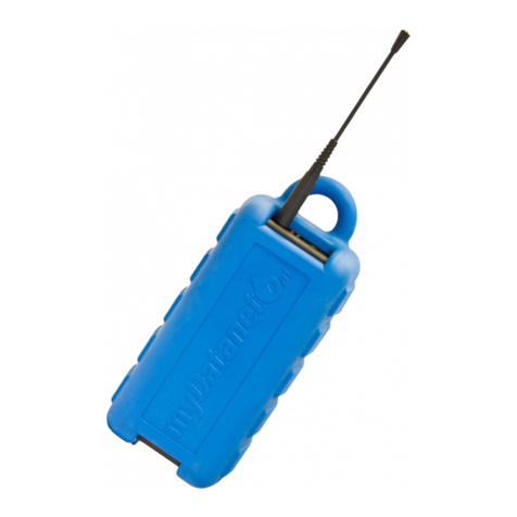
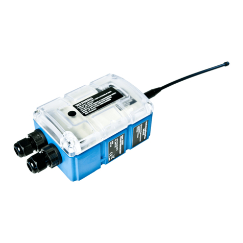
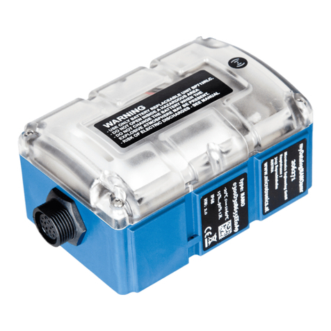
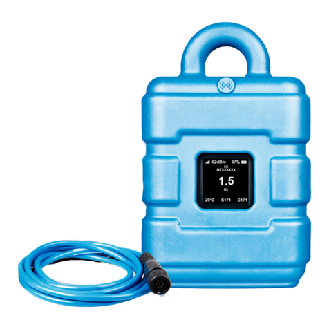
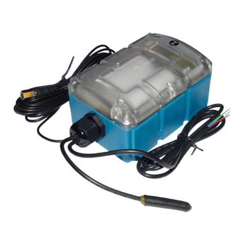
Microtronics myDatalogNANO Ex User manual

User manual for the portable ATEX data logger
myDatalogNANO Ex
Rev. 01 valid from:
lFirmware version: 03v006
lModem version: 03v004
lServer version: 40.1
lHardware version: 2.0
User manual
300489
Microtronics Engineering GmbH | www.microtronics.at
Hauptstrasse 7 | 3244 Ruprechtshofen | Austria
Tel +43 2756 77180 23 | Fax +43 2756 77180 33 | support@microtronics.at


Chapter 1 Table of contents
User manual for the portable ATEX data logger myDatalogNANO Ex 1
Chapter 1 Table of contents 3
Chapter 2 Declaration of conformity 9
2.1 Declaration of conformity - Appendix 10
Chapter 3 Technical data 13
Chapter 4 General specifications 15
4.1 Translation 15
4.2 Copyright 15
4.3 General descriptive names 15
4.4 Ex protection 16
4.5 Safety instructions 17
4.5.1 Use of the hazard warnings 17
4.5.2 General safety instructions 17
4.5.3 Safety and preventative measures for handling GSM/GPRS modems 18
4.5.3.1 Safety and precautionary measures for the installation of the GSM/GPRS modem
18
4.5.3.2 Safety measures for installing the antenna 18
4.6 Overview 19
4.6.1 Block diagram 20
4.7 Intended use 20
4.8 General product information 21
4.9 Device labelling 21
4.10 Installation of replacement and wear parts 22
4.11 Storage of the product 22
4.12 Obligation of the operator 23
Chapter 5 Functional principle 25
5.1 Internal processing of the measurement values 27
5.1.1 Filter module 27
Rev. 01 3

5.1.2 Overflow module 28
5.1.3 Scale module 28
5.1.4 Decay module 28
5.1.5 Hold module 29
5.1.6 Alarm/trigger module 30
5.1.7 Record module 31
5.1.7.1 Alarm flags 32
5.1.7.2 Trigger flags 32
5.2 Functionality of the internal data memory 32
5.3 Procedure in case of connection aborts 33
5.4 ALOHA transmission mode 34
5.5 Automatic selection of the GSM network 35
5.5.1 Ban list 36
Chapter 6 Storage, delivery and transport 37
6.1 Inspection of incoming deliveries 37
6.2 Scope of supply 37
6.3 Storage 37
6.4 Transportation 37
6.5 Return 38
Chapter 7 Installation 39
7.1 Dimensions 39
7.2 Installing the myDatalogNANO Ex 39
7.2.1 Wall mounting 40
7.2.2 Top-hat rail assembly 42
7.2.3 Pipe assembly 43
7.3 Safety instructions for the cabling 44
7.3.1 Information on preventing electrostatic discharges (ESD) 44
7.4 Electrical installation 44
7.4.1 Connecting the sensors 45
7.4.1.1 Connection examples 47
4Rev. 01

Chapter 1 Table of contents
7.4.2 Connecting the GSM antenna 47
7.4.3 Optimum antenna positioning for assembly in a shaft 48
7.4.3.1 Typical influences on the signal quality 48
7.4.3.2 Possibilities for improving the signal quality 49
7.4.3.3 Procedure for determining the optimum position of the antenna 49
7.4.4 Technical details about the universal inputs 49
7.4.4.1 Digital modes (digital, day counter, pulse counter, frequency, PWM) 50
7.4.5 Technical details about energy management 51
7.4.6 Technical details about the device operating time 51
Chapter 8 Initial Start-Up 53
8.1 User information 53
8.2 General principles 53
8.3 Commissioning the system 53
8.4 Testing communication with the device 55
Chapter 9 User interfaces 57
9.1 User interface on the myDatalogNANO Ex 57
9.1.1 Operating elements 57
9.1.1.1 Solenoid switch 57
9.1.1.2 Status LED 58
9.2 User interface on the myDatanet-Server 59
9.2.1 Site configuration 59
9.2.1.1 Site 59
9.2.1.2 Comments 59
9.2.1.3 Measurement channels 59
9.2.1.3.1 Basis 59
9.2.1.3.2 Config 61
9.2.1.3.3 Alarms 66
9.2.1.3.4 Trigger 67
9.2.1.4 Calculated channels 68
9.2.1.4.1 Basis 68
Rev. 01 5

9.2.1.4.2 Calculation 69
9.2.1.4.3 Alarms 70
9.2.1.5 Output channels 70
9.2.1.6 Internal channels 70
9.2.1.6.1 Basis 70
9.2.1.6.2 Alarms 71
9.2.1.6.3 Trigger 71
9.2.1.7 Alarm settings 72
9.2.1.8 Basic setting 73
9.2.1.9 FTP export settings 75
9.2.2 Device configuration 75
9.2.2.1 Comments 75
9.2.2.2 Measurement instrument 75
9.2.2.3 Device-specific settings 77
9.2.2.4 GPRS 77
Chapter 10 myDatanet server 79
10.1 Overview 79
10.1.1 Explanation of the symbols 79
10.2 "Customer" area 80
10.3 "Site" area at customer level 81
10.3.1 Reports 82
10.3.2 Map view 82
10.4 Recommended procedure 82
10.4.1 Creating the site 82
10.4.2 Assigning a device to the customer 83
Chapter 11 XML interface 85
11.1 General 85
Chapter 12 Maintenance 87
12.1 General maintenance 87
12.2 Replacing the battery pack 88
6Rev. 01

Chapter 1 Table of contents
Chapter 13 Removal/disposal 91
Chapter 14 Troubleshooting and repair 93
14.1 General problems 93
14.2 Log entries and error codes 94
14.2.1 Modem error 98
14.3 Evaluating the device log 101
14.3.1 Evaluating the device log on the myDatanet server 101
14.3.2 Evaluating the device log using DeviceConfig 101
Chapter 15 Spare parts and accessories 103
15.1 Assembly sets 103
15.2 Antennas 103
15.3 Battery packs 103
15.4 Cable 103
15.5 Other accessories 103
Chapter 16 Application example 105
16.1 Flow rate measurement (in lines) 105
16.1.1 Requirements 105
16.1.2 Required configuration 105
Chapter 17 Document history 107
Chapter 18 Glossary 109
Chapter 19 Contact information 111
Rev. 01 7


Chapter 2 Declaration of conformity
Rev. 01 9

2.1 Declaration of conformity - Appendix
10 Rev. 01

Chapter 2 Declaration of conformity
Rev. 01 11


Chapter 3 Technical data
Voltage supply BP713RLC Batterie : 2 x Li-SOCl2 cells fully fabricated with 13Ah
lUm: 7,8V
Housing Material: UL94HB/UL94V0 (housing/lid)
Weight: 510g (incl. battery)
Degree of protection: IP68
Dimensions (WHD): 86 x 152 x 64mm (without connection cable)
Ex certification II 3G Ex ic IIA T4 Gc
Operating
temperature
Standard: -10...+50°C, 15...90%rH non-condensing
Extended: -20...+60°C (functional parameters may be impaired)
Storage
temperature
-30...+85°C
Display LED for indicating the operating state and error codes
Operation Solenoid switch for initiating ALOHA transmission mode
Antenna
connector
TNC-F
Universal inputs 2 x digital
lUo: 7,8V
lIo: 35,8mA
lPo: 69,8mW
lCo: 21µF 1)
lLo: 1000µH 1)
Modes:
lPWM: 1...99% , max. 25Hz , min. pulse length 20ms
lFrequency: 1...25Hz
lDigital: low <2,3V, high >2,4V
lDay counter: Minimum pulse length 20ms
lInterval counter: Minimum pulse length 20ms
Additional information is provided in "Technical details about the universal
inputs" on page 49.
Data memory Internal flash memory for up to 26.360 measurement cycles
Data type f32(32 Bit floating point)
Data transmission By means of GSM/GPRS quad-band modem to the respective myDatanet server
SIM The myDatalogNANO Ex is equipped with an integrated SIM chip.
Country list profile of the SIM chip: 1 (see www.microtronics.at/footprint)
Monthly data
volume
t.b.d. at two-minute measurement cycle and 120-minute transmission cycle
Rev. 01 13

1)The specified values for Coand Loapply to the sensor connector. The values for Lcable and Ccable indicated on the type
plate of the connection cable must be taken into consideration when determining the maximum cable length.
14 Rev. 01

Chapter 4 General specifications
The information in this manual has been compiled with great care and to the best of our knowledge.
The manufacturer, however, assumes no liability for any incorrect specifications that may be
provided in this manual. The manufacturer is not responsible for direct, indirect, accidental or
consequential damages which arise from errors or omissions in this manual even if advised of the
possibility of such damages. In the interest of continuous product development, the manufacturer
reserves the right to make improvements to this manual and the products described in it at any time
and without prior notification or obligation.
Note: The specifications in this manual are valid as of the versions listed on the front page. Revised versions of this
manual, as well as software and driver updates are available in the service area of the myDatanet server.
4.1 Translation
For deliveries to countries in the European Economic Area, the manual must be translated into the
language of the respective country. If there are any discrepancies in the translated text, the original
manual (German) must be referenced or the manufacturer contacted for clarification.
4.2 Copyright
The copying and distribution of this document as well as the utilisation and communication of its
contents to others without express authorisation is prohibited. Contraventions are liable to
compensation. All rights reserved.
4.3 General descriptive names
The use of general descriptive names, trade names, trademarks and the like in this manual does not
entitle the reader to assume they may be used freely by everyone. They are often protected
registered trademarks even if not marked as such.
Rev. 01 15

4.4 Ex protection
The portable instrument myDatalogNANO Ex designed for use in areas with a zone2 explosive
atmosphere.
The following conditions must be adhered to:
lOnly the manufacturer's original spare parts must be used.
lDuring installation, it must be ensured that the device is protected against light (e.g. day light,
artificial lighting) and it must be installed in such a way that the light resistance requirements
as per IEC60079-0 are met.
lThe installation must be executed in such a way that there is no risk of ignition during
intended use, maintenance and cleaning caused by electrostatic charges.
lThe housing must only be opened outside the EX area.
lWithin the Ex area, the device must only be operated with the "Cable set NANO ATEX zone II"
connection cable (fitted ex works).
lThe device may only be mounted or installed if no explosive atmosphere is present. It must be
ensured that the protection level (voltage), clearances, isolation distances, creepage distances
and comparative tracking index are adhered to.
lThe device must only be operated with battery pack BP713RLC.
lThe battery pack BP713RLC must only be replaced outside the Ex area
lBattery pack BP713RLC must only be installed in "NANO" type devices(see "Device labelling"
on page 21).
II 3G Ex ic IIA T4 Gc
Important note: The Ex approval is only valid if the corresponding marking is provided on
the type plate of the measurement instrument .
Important note: The certificates of conformity and any relevant test certificates from the
respective authorities must be carefully observed during installation and commissioning.
1myDatalogNANO Ex 2Impulse sensor approved for the Ex zone
16 Rev. 01

Chapter 4 General specifications
4.5 Safety instructions
For the connection, commissioning and operation of the myDatalogNANO Ex , the following
information and higher legal regulations of the country (e.g. ÖVE), such as valid EX regulations as
well as the applicable safety and accident prevention regulations for the respective application case
must be observed.
Please read this manual completely before unpacking, setting up or operating this device. Observe
all hazard, danger and warning information. Non-observance can lead to serious injuries to the
operator and/or damage to the device.
Ensure that the safety equipment of this measurement device is not impaired. Install and use the
measuring system only in the manner and method described in this manual.
Important note: The manufacturer's products that are designed for use outdoors include
extensive protection against penetrating moisture and dust.
4.5.1 Use of the hazard warnings
DANGER:
Indicates a potential or threatening hazardous situation that will result in death or serious
injuries if not avoided.
WARNING:
Indicates a potential or threatening hazardous situation that can result in death or serious
injuries if not avoided.
CAUTION:
Indicates a potential hazardous situation that can result in minor or moderate injury.
Note: Indicates a situation that does not result in any injury to persons.
Important note: Indicates a situation that can result in damages to this instrument if it is not
avoided. Information that must be particularly emphasised.
Note: Information that supplements the specifications in the main text.
4.5.2 General safety instructions
WARNING:
Never use this device in areas where the use of radio equipment is prohibited. This device
must not be used in hospitals and/or in the vicinity of medical equipment, such as
pacemakers or hearing aids, as their functionality could be compromised by the GSM/GPRS
modem contained in the device.
Rev. 01 17

4.5.3 Safety and preventative measures for handling GSM/GPRS modems
Observe the following safety and preventative measures during all phases of installation, operation,
maintenance or repair of a GSM/GPRS modem. The manufacturer shall not be held liable if the
customer disregards these preventative measures.
CAUTION:
The GSM/GPRS modem connection may not be used in hazardous environments.
No guarantee of any kind, whether implicit or explicit, is given by the manufacturer and its
suppliers for the use with high risk activities.
In addition to the following safety considerations, all directives of the country in which the device is
installed must be complied with.
Important note: No liability shall be assumed at any time and under no condition for the
connection via a GSM/GPRS modem for whose use radio signals and networks are utilized,
The GSM/GPRS modem must be switched on and be operated in an area where sufficient
signal strength is present.
4.5.3.1 Safety and precautionary measures for the installation of the GSM/GPRS modem
lThis device must only be installed by a trained technician who applies the recognised
installation practices for a radio frequency transmitter including the correct grounding of
external antennas.
lThe device must not be operated in hospitals and/or in the vicinity of medical equipment such
as heart pacemakers or hearing aids.
lThe device must not be operated in highly flammable areas such as petrol filling stations, fuel
storage sites, chemical factories and explosion sites.
lThe device must not be operated in the vicinity of flammable gases, vapours or dusts.
lThe device must not be subjected to strong vibrations or impacts.
lThe GSM/GPRS modem can cause interferences if it is located in the vicinity of television sets,
radios or computers.
lDo not open the GSM/GPRS modem. Any modification to the equipment is prohibited and will
result in the operating licence being revoked.
lThe use of GSM services (SMS messages/data communication/GPRS, etc.) may incur additional
costs. The user is solely responsible for any resulting damages and costs.
lDo not install the device in any other way to the one described in the operating instructions.
Improper use will invalidate the warranty.
4.5.3.2 Safety measures for installing the antenna
lOnly use antennas that are recommended or supplied by the manufacturer.
lThe antenna must be installed at a distance of at least 20 cm from individuals.
lThe antenna must not be extended outside protected buildings and must be protected against
lightning strikes.
lThe voltage supply must be switched off before replacing the antenna.
18 Rev. 01

Chapter 4 General specifications
4.6 Overview
Important note: Within the Ex area, the myDatalogNANO Ex must only be operated with the
"Cable set NANO ATEX zone II " connection cable (300252 , included in the scope of supply
of the myDatalogNANO Ex ).
Overview myDatalogNANO Ex
1Clamping tube(300256 , simple electrical
equipment included in the scope of delivery
of 300469 )
4Housing cover
2Cable set NANO ATEX zone II (300252 ,
included in the scope of supply of 300469 )
5Antenna connector
3Connector for the sensor cable
Rev. 01 19

4.6.1 Block diagram
Block diagram of the myDatalogNANO Ex
4.7 Intended use
The portable measurement instrument is used to collect digital signals. The device can operate
without mains power. The measured and recorded data is stored on a non-volatile memory medium.
This stored data is sent via the mobile network to a central server for further processing. The device
is equipped with an integrated SIM chip for this purpose. The maximum permissible limit values
specified in chapter "Technical data" on page 13 must be observed. The manufacturer shall not be
liable for any operational cases that deviate from these limit values and have not been approved by
the manufacturer in writing.
20 Rev. 01
Table of contents
Other Microtronics Data Logger manuals
Microtronics
Microtronics myDatalogMUC xG/4G User manual

Microtronics
Microtronics myDatalogEx User manual

Microtronics
Microtronics myDatalogNANOamr User manual

Microtronics
Microtronics myDatalog4 User manual

Microtronics
Microtronics myDatalogEASY V3 User manual

Microtronics
Microtronics myDatalogGauge 3G User manual

Microtronics
Microtronics myDatalog2Ex User manual
Microtronics
Microtronics myDatalogEASYplus User manual

Microtronics
Microtronics myDatasensMINI H2S 1000 User manual
Microtronics
Microtronics myDatalogMUC User manual