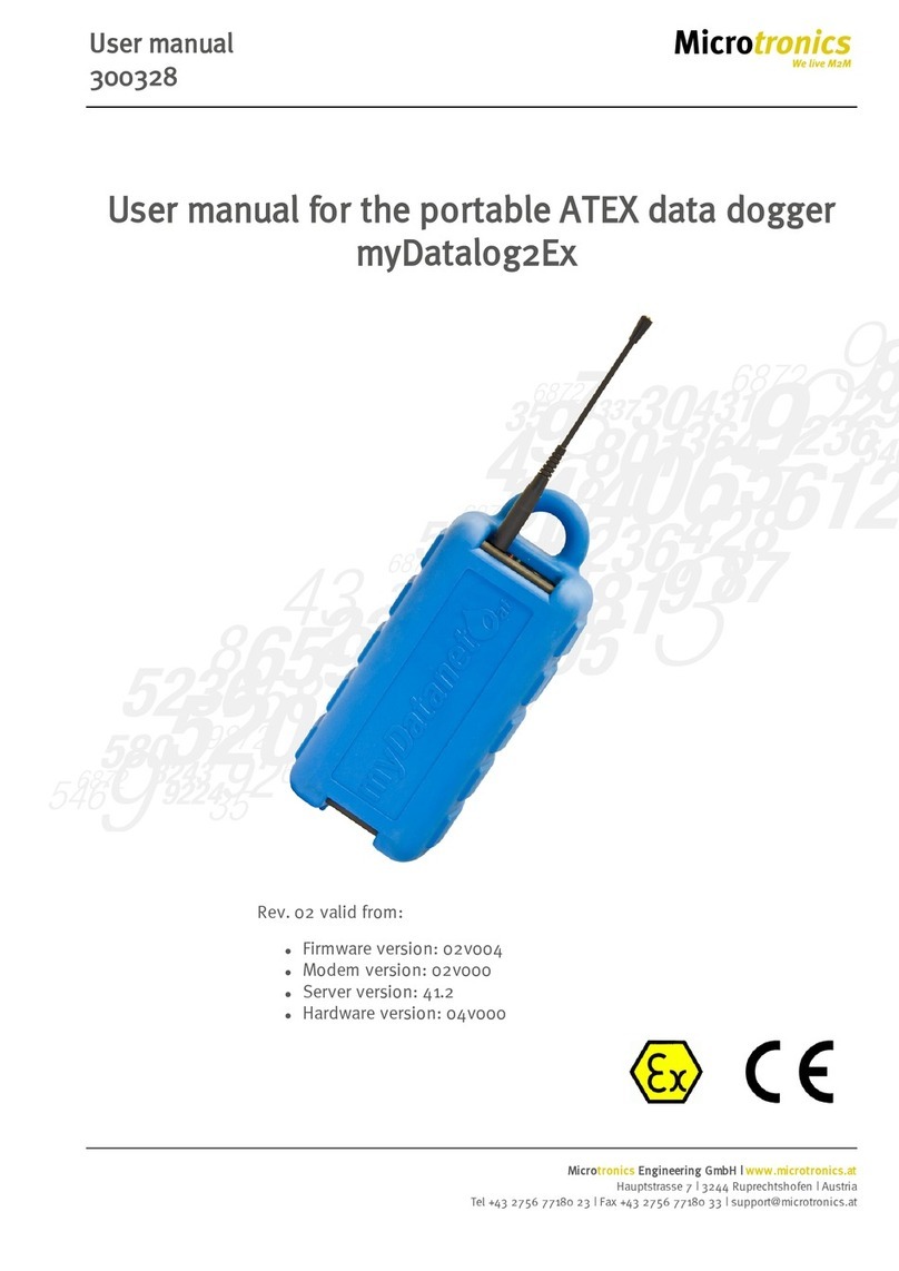
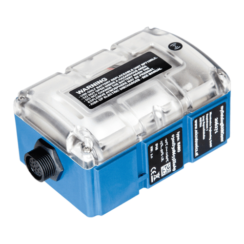
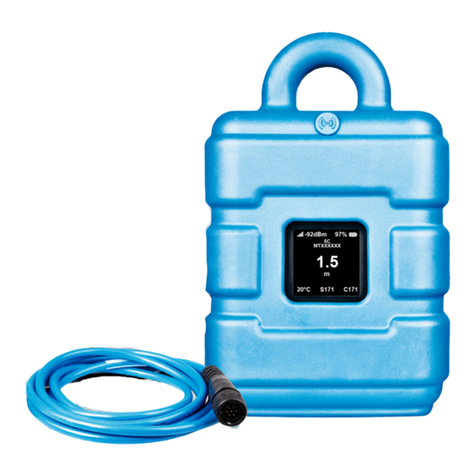
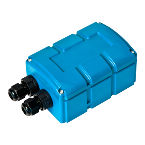
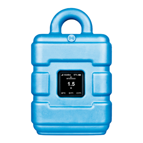
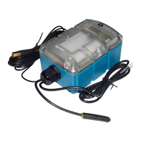
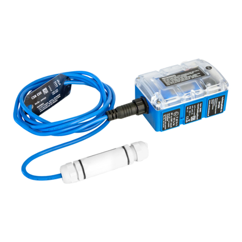
Microtronics myDatalogEASY V3 User manual

300574 | Rev.05
Cover
Valid from:
lFirmware version: 01v015
lServer version: 49v011
lHardware version: 4.0
User manual
myDatalogEASY V3


Chapter 1 Table of contents
Cover 1
Chapter 1 Table of contents 3
Chapter 2 Declaration of conformity 13
Chapter 3 Technical data 15
Chapter 4 General specifications 19
4.1 Translation 19
4.2 Copyright 19
4.3 General descriptive names 19
4.4 Safety instructions 19
4.4.1 Use of the hazard warnings 20
4.4.2 General safety instructions 20
4.4.3 Safety and preventative measures for handling GSM/GPRS modems 21
4.4.3.1 Safety and precautionary measures for the GSM/GPRS modem installation 21
4.4.3.2 Safety measures for installing the antenna 21
4.5 Overview 22
4.5.1 Block diagram 23
4.6 Intended use 24
4.7 General product information 24
4.8 Device labelling 25
4.9 Installation of spare and wear parts 26
4.10 Storage of the product 26
4.11 Warranty 27
4.12 Disclaimer 27
4.13 Obligation of the operator 27
4.14 Personnel requirements 28
Chapter 5 Functional principle 29
5.1 Recommended procedure 31
5.1.1 Development of M2M/IoT application 31
5.2 Functionality of the internal data memory 31
5.3 Memory organisation 33
5.4 Procedure in case of connection aborts 34
Rev. 05 3

5.4.1 Connection abort in "online" mode 35
5.4.2 Connection abort during a Device Logic download 35
5.5 Automatic selection of the GSM network 35
5.6 Determining the GSM/UMTS/LTE signal strength 35
5.7 Determining the GSM position data 35
5.8 Error handling 36
5.9 Registration memory blocks 36
5.9.1 REG_APP_OTP 37
5.10 File transfer 37
5.11 Meaning of the SIM state 38
5.12 Using the external SIM slot 39
Chapter 6 Storage, delivery and transport 43
6.1 Inspection of incoming deliveries 43
6.2 Scope of supply 43
6.3 Storage 44
6.4 Transport 44
6.4.1 Transporting power supply units 44
6.5 Return 46
Chapter 7 Installation 47
7.1 Dimensions 47
7.2 Assembling the myDatalogEASYV3 47
7.3 Inserting/replacing the SIM card 53
7.4 Installing the myDatalogEASYV3 55
7.4.1 Wall mounting 56
7.4.2 Top-hat rail assembly 57
7.4.3 Pipe assembly 58
7.5 Safety instructions for the cabling 59
7.5.1 Information on preventing electrostatic discharges (ESD) 60
7.6 Electrical installation 60
7.6.1 Connecting the sensors, actuators and power supply 60
7.6.1.1 Connection examples 64
7.6.2 Connecting the GSM antenna 64
7.6.3 Technical details about the universal inputs 65
4Rev. 05

Chapter 1 Table of contents
7.6.3.1 0/4 to 20mA mode 65
7.6.3.2 0 to 2V mode 65
7.6.3.3 0 to 10V mode 65
7.6.3.4 Standard digital modes (PWM, frequency, digital, counter) 66
7.6.4 Technical details about the PT100/1000 interface 66
7.6.5 Technical details about the RS485 interface 66
7.6.6 Technical details about the RS232 interface 67
7.6.7 Technical details about the USB interface 68
7.6.8 Technical details about the outputs 69
7.6.8.1 Switchable sensor supply VOUT 69
7.6.8.2 Switchable sensor supply VEXT 70
7.6.8.3 Switchable sensor supply VEXTRS232 71
7.6.8.4 Isolated switch contact (NO, CC) 71
7.6.9 Technical details about energy management 71
7.6.10 Technical details about the energy supply 72
7.6.10.1 PSU413D+ AP (300524) 73
7.6.10.2 PSU413D AP (300525) 74
7.6.10.3 PSU713 BP (300526) 74
7.6.10.4 PSU DC (300529) 74
7.6.10.5 PSU AC (300558) 75
7.6.10.6 PSU DC+ (300798) 75
7.6.11 Technical details about the system time 75
Chapter 8 Initial Start-Up 77
8.1 User information 77
8.2 Applicable documents 77
8.3 General principles 77
8.4 Commissioning the system 77
8.5 Testing communication with the device 79
Chapter 9 User interfaces 81
9.1 User interface on the myDatalogEASYV3 81
9.1.1 Operating elements 81
9.1.1.1 Solenoid switch 81
9.1.1.2 Two-colour LED 81
Rev. 05 5

9.2 User interface on the myDatanet server 82
9.2.1 Site configuration 82
9.2.1.1 Site 82
9.2.1.2 Comments 82
9.2.1.3 Control 83
9.2.1.4 Configuration 0 - Configuration 9 83
9.2.1.5 Alarm settings 84
9.2.1.6 Basic settings 85
9.2.1.7 FTP export settings 85
9.2.2 Device configuration 86
9.2.2.1 Comments 86
9.2.2.2 Measurement instrument 86
9.2.2.3 GPRS 87
Chapter 10 DeviceConfig 89
10.1 General 89
10.2 Prerequisites 89
10.3 Functional principle 90
10.4 Installation 91
10.5 Menu of the DeviceConfig 93
10.5.1 Settings 93
10.5.1.1 Options 93
10.6 Connecting a Device via USB 95
10.7 "GSM" tab 96
10.8 "Log" tab 98
10.9 "Firmware" tab 100
10.10 "Features" tab 101
Chapter 11 myDatanet server 103
11.1 Overview 103
11.1.1 Explanation of the symbols 103
11.2 "Customer" area 104
11.3 "Site" area at customer level 106
11.3.1 Reports 107
11.3.2 Map view 107
6Rev. 05

Chapter 1 Table of contents
11.4 Recommended procedure 107
11.4.1 Creating the site 107
Chapter 12 rapidM2M Studio 111
12.1 General 111
12.2 Prerequisites 112
12.3 Project dashboard 113
12.4 CODEbed 114
12.5 TESTbed 115
Chapter 13 Device Logic (Pawn) 117
13.1 General 117
13.1.1 Direct entry of a device logic 117
13.1.2 Uploading a binary file 117
13.1.3 Using the CODEbed of the web-based development environment rapidM2M Studio 117
13.2 rapidM2M Device API 118
13.2.1 Constants 118
13.2.2 Timer, date & time 119
13.2.2.1 Arrays with symbolic indices 119
13.2.2.2 Constants 119
13.2.2.3 Functions 119
13.2.3 Uplink 124
13.2.3.1 Arrays with symbolic indices 124
13.2.3.2 Constants 124
13.2.3.3 Callback functions 128
13.2.3.4 Functions 129
13.2.4 System 138
13.2.4.1 Arrays with symbolic indices 138
13.2.4.2 Constants 138
13.2.4.3 Functions 139
13.2.5 Encoding 141
13.2.5.1 Constants 141
13.2.5.2 Functions 142
13.2.6 RS232, RS485 147
13.2.6.1 Constants 147
Rev. 05 7

13.2.6.2 Callback functions 147
13.2.6.3 Functions 149
13.2.7 Registry 155
13.2.7.1 Constants 155
13.2.7.2 Callback functions 156
13.2.7.3 Functions 156
13.2.8 Position 160
13.2.8.1 Arrays with symbolic indices 160
13.2.8.2 Constants 162
13.2.8.3 Functions 163
13.2.9 Math 169
13.2.10 Char & String 172
13.2.11 CRC & hash 177
13.2.11.1 Arrays with symbolic indices 177
13.2.11.2 Functions 177
13.2.12 Various 178
13.2.12.1 Arrays with symbolic indices 178
13.2.12.2 Constants 179
13.2.12.3 Functions 179
13.2.13 Console 185
13.2.14 SMS 186
13.2.14.1 Callback functions 186
13.2.14.2 Functions 186
13.2.15 External SIM 187
13.2.15.1 Arrays with symbolic indices 187
13.2.15.2 Functions 187
13.2.16 File transfer 188
13.2.16.1 Arrays with symbolic indices 188
13.2.16.2 Constants 188
13.2.16.3 Callback functions 189
13.2.16.4 Functions 190
13.2.17 Universal inputs 194
13.2.17.1 Constants 194
8Rev. 05

Chapter 1 Table of contents
13.2.17.2 Functions 195
13.2.18 Outputs 198
13.2.18.1 Constants 198
13.2.18.2 Functions 198
13.2.19 LED 203
13.2.19.1 Constants 203
13.2.19.2 Functions 204
13.2.20 Solenoid switch 206
13.2.20.1 Constants 206
13.2.20.2 Callback Funktionen 206
13.2.20.3 Functions 207
13.2.21 Power management 208
13.2.21.1 Arrays with symbolic indices 208
13.2.21.2 Constants 208
13.2.21.3 Callback functions 209
13.2.21.4 Functions 209
13.3 Device Logic error codes 210
13.4 Syntax 213
13.4.1 General syntax 213
13.4.1.1 Format 213
13.4.1.2 Optional semicolons 213
13.4.1.3 Comments 213
13.4.1.4 Identifier 213
13.4.1.5 Reserved keywords 213
13.4.1.6 Numerical constants 214
13.4.1.6.1 Numerical integer constants 214
13.4.1.6.2 Numerical floating-point constants 214
13.4.2 Variables 214
13.4.2.1 Declaration 214
13.4.2.2 Local declaration 214
13.4.2.3 Global declaration 214
13.4.2.4 Static local declaration 215
13.4.2.5 Static global declaration 215
Rev. 05 9

13.4.2.6 Floating point values 215
13.4.3 Constant variables 215
13.4.4 Array variables 215
13.4.4.1 One-dimensional arrays 215
13.4.4.2 Initialisation 216
13.4.4.3 Progressive initialisation for arrays 216
13.4.4.4 Multi-dimensional arrays 216
13.4.4.5 Arrays and the "sizeof" operator 217
13.4.5 Operators and expressions 218
13.4.5.1 Notational conventions 218
13.4.5.2 Expressions 218
13.4.5.3 Arithmetic 218
13.4.5.4 Bit manipulation 219
13.4.5.5 Assignment 219
13.4.5.6 Comparative operators 220
13.4.5.7 Boolean 220
13.4.5.8 Other 221
13.4.5.9 Priority of the operators 221
13.4.6 Statements 222
13.4.6.1 Statement label 222
13.4.6.2 Composite statements 223
13.4.6.3 Expression statement 223
13.4.6.4 Empty statement 223
13.4.6.5 Assert expression 223
13.4.6.6 Break 224
13.4.6.7 Continue 224
13.4.6.8 Do statement while (expression) 225
13.4.6.9 Exit expression 225
13.4.6.10 For (expression1; expression2; expression3) statement 225
13.4.6.11 Goto label 226
13.4.6.12 If (expression) statement1 else statement2 226
13.4.6.13 Return expression 226
13.4.6.14 switch (expression) {case list} 226
10 Rev. 05

Chapter 1 Table of contents
13.4.6.15 While (expression) statement 227
13.4.7 Functions 228
13.4.7.1 Function arguments ("call-by-value" versus "call-by-reference") 228
13.4.7.2 Named parameters versus fixed parameters 230
13.4.7.3 Standard values of function arguments 230
13.5 Differences to C 231
Chapter 14 Data Descriptor 235
14.1 Data structure 235
14.1.1 Division of a structured measurement data channel into individual data fields 236
14.1.2 Division of a configuration memory block into individual data fields 237
14.1.3 Division of the aloha data into individual data fields 238
14.1.4 Attributes of the field definition 238
14.2 Example 241
14.3 Special values of the data types 243
Chapter 15 API 245
15.1 Frontend API 245
15.2 rapidM2M Playground 245
15.2.1 Overview 246
Chapter 16 Maintenance 247
16.1 General maintenance 247
16.2 Replacing the power supply unit 247
16.2.1 Charging the power supply unit 249
16.3 Power supply units with integrated energy store 251
Chapter 17 Removal/disposal 253
Chapter 18 Troubleshooting and repair 255
18.1 General problems 255
18.2 Log entries and error codes 257
18.2.1 Modem error 260
18.3 Evaluating the device log 262
18.3.1 Evaluating the device log on the myDatanet server 262
18.3.2 Evaluating the device log using DeviceConfig 262
Chapter 19 Spare parts and accessories 263
19.1 Chargeable features 263
Rev. 05 11

Chapter 2 Declaration of conformity
Rev. 05 13


Chapter 3 Technical data
Voltage supply Rechargeable battery:
lPSU413D+ AP : 13,6Ah, Li-Ion , integrated overvoltage protection
lPSU413D AP : 13,2Ah, Li-Ion , integrated overvoltage protection
Battery:
lPSU713 BP : 13Ah
Direct power supply:
lPSU DC : DC protective circuit
lPSU DC+ : 900mAh, Li-Po , DC protective circuit
lPSU AC : 900mAh, Li-Po , 230VAC power supply unit
Additional information is provided in "Technical details about the energy supply" on
page 72.
Supply or charging
voltage
12...32VDC (max. 12W )
Housing Material:
Weight:
Protection class:
Dimensions (WHD):
ABS / PC (housing/cover)
330g (without power supply unit)
IP66
86 x 175 x 64mm (without antenna)
Operating
temperature
-20...+60°C
Air humidity 15...90%rH non-condensing
Storage
temperature
-30...+85°C
Display Two-colour LED with selectable function:
lSignalling the operating state (controlled by the FW)
lFunction freely useable (controlled by the Device Logic)
Operation Solenoid switch with selectable function:
lInitiation of the transmission (evaluated by the FW)
lFunction freely selectable (evaluated by the Device Logic)
Antenna connector FME-M
Rev. 05 15

Universal inputs1) 4 x analogue or digital
Modes:
l0/4...20mA: Resolution 6,3µA, max. 23,96mA, load 96Ω
l0...2V: Resolution 610µV, max. 2,5V, load 10k086
l0...10V: Resolution 7,97mV, max. 32V, load 4k7
lPWM: 1...99%, max. 100Hz, min. pulse length 1ms, load 10k086
lFrequency: 1...1000Hz, 10k086
lDigital: max. 32V, low <0,99V, high >2,31V, load 10k086
lCounter: min. pulse length 1ms, load 10k086
Additional information is provided in "Technical details about the universal inputs" on
page 65.
System time Hardware real-time clock with its own buffer battery and automatic time
synchronisation with the server.
Additional information is provided in "Technical details about the system time" on page
75.
Internal sensors Internal housing temperature
lMeasurement range: -20...+60°C
lResolution: 0,1°C
Humidity in the housing
lMeasurement range: 0...100% rH
lResolution: 0,1% rH
External
temperature sensor
2)
1 x PT100/1000 (including auto detection)
Additional information is provided in "Technical details about the PT100/1000
interface" on page 66.
Serial interface 1 x RS232 (4-wire) 3)
lBaud rate: 600-115200
lStop bits: 1, 2
lParity: N, E, O
lData bits: 7, 8
lFlow control: Off, RTS/CTS
1 x RS485 (2-wire) 4) 5)
lBaud rate: 600-115200
lStop bits: 1, 2
lParity: N, E, O
lData bits: 7, 8
lLoad resistance: Off, 120Ω
Additional information is provided in "Technical details about the RS485 interface" on
page 66 and "Technical details about the RS232 interface" on page 67.
16 Rev. 05

Chapter 3 Technical data
Outputs 2 x switchable 3,3V supply (max. 180mA )
1 x switchable and adjustable sensor supply:
The device logic can be used to vary the output voltage in the range of 5...24V .
l5Vnominal: 4,75V at Iout = 50mA
l12Vnominal: 11,7V at Iout = 50mA
l15Vnominal: 14,7V at Iout = 50mA
l24Vnominal: 23,4V at Iout = 50mA
1 x isolated switch contact:
lImax: 130mA
lUmax: 32V
lRon: 35Ω
lfmax: 1000Hz
Modes:
lDigital
lFrequency: Adjustment range 1...1000Hz, pulse duty factor 1...100%
lPWM: Adjustment range 0...100%, frequency 0...1000Hz
lPulse: Pulse duration 1...500ms , pulse pause 1...500ms
lPulse/min
Additional information is provided in "Technical details about the outputs" on page 69.
Bluetooth 6) 5.0 compatible low energy module
USB interface 1 x mini-B USB 2.0 slave for the connection to a PC. The DeviceConfig configuration
program must be installed on the PC or the web-based development environment
rapidM2M Studio must be used to enable communication with the
myDatalogEASYV3 .
Additional information is provided in "Technical details about the USB interface" on
page 68.
Data memory 3MB internal flash memory.
The size of the data records is variable (max. 1024 Byte ) and is determined by the
Device Logic created by the user. The system-related overhead is 11 Byte per data
record.
Additional information is provided in"Functionality of the internal data memory" on
page 31.
Configuration
memory
10 independent blocks each with 4000 Byte
Rev. 05 17

Registration
memory
Flash: 4 blocks each with 1kB and pre-defined purposes for storing device-specific
data
RAM: 1 optional block with maximum 1kB for storing application-specific data
Additional information is provided in "Registration memory blocks" on page 36.
Memory for the
PAWN binary
256kB (uncompressed size)
Additional information is provided in "Memory organisation" on page 33.
Data transmission 2G/3G world:
l2G GPRS 900MHz / 1800MHz
l2G GPRS 850MHz / 1900MHz
lUMTS B1, B2, B5, B8, B19
SIM 7) The following options can be selected using the DeviceConfig configuration program:
lIntegrated SIM chip
lSIM slot
Additional information is provided in "Using the external SIM slot" on page 39
1) The universal inputs 3 and 4 are only available if the RS485 interface is not used.
2In order for the external temperature sensor to be used, the chargeable feature "Activation code temperature
input(300542)" must be unlocked or order option "Feature activation temperature input (300732)" is required.
3) In order for the RS232 interface to be used, the chargeable feature "Activation code RS232 (300541)" must be unlocked
or order option "Feature activation RS232 (300731)" is required.
4) In order for the RS485 interface to be used, the chargeable feature "Activation code RS485 (300540)" must be unlocked
or order option "Feature activation RS485 (300730)" is required.
5) The RS485 interface is only available if the universal inputs 3 and 4 are not being used.
6) reserved for extensions
7) In order for the SIM slot to be used, the chargeable feature "Activation code VPN SIM (300539)" must be unlocked or
order option "Feature activation VPN SIM (300729)" is required.
18 Rev. 05

Chapter 4 General specifications
The information in this manual has been compiled with great care and to the best of our knowledge. The
manufacturer, however, assumes no liability for any incorrect specifications that may be provided in this
manual. The manufacturer is not responsible for direct, indirect, accidental or consequential damages which
arise from errors or omissions in this manual even if advised of the possibility of such damages. In the interest
of continuous product development, the manufacturer reserves the right to make improvements to this
manual and the products described in it at any time and without prior notification or obligation.
Note: The specifications in this manual are valid as of the versions listed on the front page. Revised versions
of this manual, as well as software and driver updates are available in the service area of the myDatanet
server.
4.1 Translation
For deliveries to countries in the European Economic Area, the manual must be translated into the language
of the respective country. If there are any discrepancies in the translated text, the original manual (German)
must be referenced or the manufacturer contacted for clarification.
4.2 Copyright
The copying and distribution of this document as well as the utilisation and communication of its contents to
others without express authorisation is prohibited. Contraventions are liable to compensation. All rights
reserved.
4.3 General descriptive names
The use of general descriptive names, trade names, trademarks and the like in this manual does not entitle
the reader to assume they may be used freely by everyone. They are often protected registered trademarks
even if not marked as such.
4.4 Safety instructions
For the connection, commissioning and operation of the myDatalogEASYV3 , the following information and
higher legal regulations of the country (e.g. ÖVE), such as valid EX regulations as well as the applicable
safety and accident prevention regulations for the respective application case must be observed.
Read this manual completely before unpacking, setting up or operating this device. Observe all hazard,
danger and warning information. Non-observance can lead to serious injuries to the operator and/or damage
to the device.
Ensure that the safety equipment of this measurement instrument is not impaired. Install and use the
measurement system only in the manner and method described in this manual.
Rev. 05 19

Important note: The manufacturer's products that are designed for use outdoors include extensive
protection against penetrating moisture and dust. If these productsare connected to the power supply
or sensors by cables with connectors rather than permanently installed cables, the susceptibility of the
connector and socket to moisture and dust penetration is significantly higher. The operator is
responsible for protecting the connector and socket against penetrating moisture and dust in a
suitable way and complying with local safety regulations.
4.4.1 Use of the hazard warnings
DANGER:
Indicates a potential or threatening hazardous situation that will result in death or serious
injuries if not avoided.
WARNING:
Indicates a potential or threatening hazardous situation that can result in death or serious
injuries if not avoided.
CAUTION:
Indicates a potential hazardous situation that can result in minor or moderate injuries or
damage to this instrument.
Important note: Indicates a situation that can result in damages to this instrument if it is not avoided.
Information that must be particularly emphasised.
Note: Indicates a situation that does not result in any injury to persons.
Note: Information that supplements the specifications in the main text.
4.4.2 General safety instructions
WARNING:
Hazardous electric voltage can cause electric shock or burns. Always switch off all of the
used power supplies for the device before installing it, completing any maintenance work
or resolving any faults.
WARNING:
Ensure that the device is fully deactivated and cannot activate automatically when
sending/returning it as air freight. Information on this is provided in chapter "Storage of
the product" on page 26. If you have any unanswered questions, contact the manufacturer
(see "Contact information" on page 277).
WARNING:
Never use this device in areas where the use of wireless equipment is prohibited. The
device must not be used in hospitals and/or in the vicinity of medical equipment, such as
heart pacemakers or hearing aids, as their functionality could be compromised by the
GSM/GPRS modem contained in the device.
WARNING:
Never use this device in potentially explosive atmospheres and in the vicinity of highly
combustible areas (fuel stations, storage areas for combustible material, chemical plants
and detonation sites) or in the vicinity of flammable gases, vapours or dust.
20 Rev. 05
Table of contents
Other Microtronics Data Logger manuals

Microtronics
Microtronics myDatalogMUC xG/4G User manual

Microtronics
Microtronics myDatasensMINI H2S 1000 User manual

Microtronics
Microtronics myDatalogGauge 3G User manual

Microtronics
Microtronics myDatalogEASYplus User manual

Microtronics
Microtronics myDatalogNANO Ex User manual

Microtronics
Microtronics myDatalogEx User manual

Microtronics
Microtronics myDatalog2Ex User manual

Microtronics
Microtronics myDatalogNANO User manual

Microtronics
Microtronics myDatalogNANOamr User manual

Microtronics
Microtronics myDatalogMUC User manual