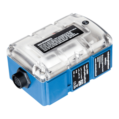
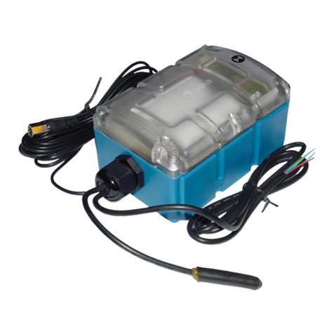
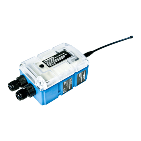
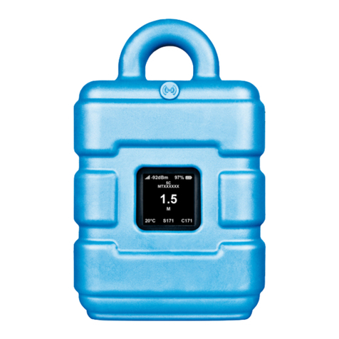
Microtronics myDatalogMUC User manual

300101 | Rev.06
Cover
Valid from:
lFirmware version: 03v002
lModem Version: 03v014
lServer version: 44.1
lHardware version: 1.0
User manual
myDatalogMUC


Chapter 1 Table of contents
Cover 1
Chapter 1 Table of contents 3
Chapter 2 Declaration of conformity 13
Chapter 3 Technical data 15
Chapter 4 General specifications 19
4.1 Translation 19
4.2 Copyright 19
4.3 General descriptive names 19
4.4 Safety instructions 19
4.4.1 Use of the hazard warnings 20
4.4.2 General safety instructions 20
4.4.3 Safety and preventative measures for handling GSM/GPRS modems 20
4.4.3.1 Safety and precautionary measures for the installation of the GSM/GPRS modem 21
4.4.3.2 Safety measures for installing the antenna 21
4.5 Overview 22
4.5.1 Block diagram 22
4.6 Intended use 24
4.7 General product information 24
4.8 Device labelling 25
4.9 Installation of spare and wear parts 25
4.10 Storage of the product 26
4.11 Obligation of the operator 26
4.12 Personnel requirements 26
Chapter 5 Functional principle 29
5.1 Internal processing of the measurement values 31
5.1.1 Filter module 32
5.1.2 Overflow module 33
5.1.3 Scale module (inputs) 34
5.1.4 Decay module 35
5.1.5 Hold module 36
5.1.6 Alarm/trigger module 36
Rev. 06 3

5.1.7 Control module 36
5.1.8 Record module 38
5.1.9 Setpoint module 39
5.1.10 Scale module (outputs) 40
5.2 Functionality of the internal data memory 40
5.3 Use of the communication channels 41
5.3.1 Behaviour in connection modes when using both communication channels 42
5.3.1.1 Interval 42
5.3.1.2 Interval & wakeup 42
5.3.1.3 online 42
5.3.1.4 ALOHA 43
5.4 Procedure in case of connection aborts 43
5.5 ALOHA transmission mode 44
5.6 Automatic selection of the GSM network 45
5.6.1 Ban list 45
5.7 Script eradication 46
5.7.1 Script parsing 46
Chapter 6 Storage, delivery and transport 51
6.1 Inspection of incoming deliveries 51
6.2 Scope of supply 51
6.3 Storage 51
6.4 Transport 51
6.5 Return 52
Chapter 7 Installation 53
7.1 Dimensions 53
7.2 Installing the myDatalogMUC 53
7.2.1 Top-hat rail assembly 54
7.2.2 Assembly in a control cabinet 54
7.3 Safety instructions for the cabling 55
7.3.1 Information on preventing electrostatic discharges (ESD) 56
7.4 Electrical installation 56
7.4.1 Connecting the sensors, actuators and power supply 56
7.4.1.1 Connection examples 61
4Rev. 06

Chapter 1 Table of contents
7.4.2 Connection of the GSM antenna 61
7.4.3 Technical details about the universal inputs 62
7.4.3.1 0/4 to 20mA mode 62
7.4.3.2 0 to 2V mode 62
7.4.3.3 0 to 10V mode 62
7.4.3.4 Standard digital modes (PWM, frequency, digital, day counter, impulse counter) 62
7.4.4 Technical details about the PT100/1000 interface 63
7.4.5 Technical details about the modbus interfaces (Com1, Com3) 63
7.4.5.1 Modbus-Slave Modus 65
7.4.6 Technical details about the RS232 interface (Com2) 65
7.4.6.1 Error codes of the RS232 interface 66
7.4.7 Technical details about the outputs 67
7.4.7.1 Analogue output1-2 (OUT, GND) 67
7.4.7.2 Relay1-6 67
7.4.8 Technical details about the integrated rechargeable buffer battery 68
7.4.9 Technical details regarding the energy supply 70
Chapter 8 Initial Start-Up 71
8.1 User information 71
8.2 General principles 71
8.3 Placing the system into operation 71
8.4 Testing communication with the device 72
Chapter 9 User interfaces 75
9.1 User interface on the myDatalogMUC 75
9.1.1 Operating elements 75
9.1.1.1 Button to initiate ALOHA transmission mode 75
9.1.1.2 Status LED 76
9.1.1.3 Status indication: Self-testing 77
9.1.1.4 Status display: buffer accu active 78
9.1.1.5 Button to initiate self-testing 78
9.1.1.6 Status display: Switching states of the relays 78
9.2 User interface on the myDatanet server 78
9.2.1 Site configuration 78
9.2.1.1 Site 79
Rev. 06 5
9.2.1.2 Comments 79
9.2.1.3 Control 79
9.2.1.4 Interfaces 80
9.2.1.4.1 Basis 80
9.2.1.4.1.1 Com1 and Com3 (modbus master, RS485, script parsing inactive) 80
9.2.1.4.1.2 Com1 and Com3 (modbus slave, RS485, script parsing inactive) 83
9.2.1.4.1.3 Com1 and Com3 (RS485, script parsing active) 84
9.2.1.4.1.4 Com2 (serial, RS232) 87
9.2.1.4.2 Config 90
9.2.1.4.2.1 Com1 and Com3 90
9.2.1.4.2.2 Com2 91
9.2.1.5 Sequences for COM2 91
9.2.1.6 Measurement channels 92
9.2.1.6.1 Basis 92
9.2.1.6.2 Config 95
9.2.1.6.3 Alarms 108
9.2.1.6.4 Trigger 109
9.2.1.7 Interface channels1-32 110
9.2.1.7.1 Basis 110
9.2.1.7.2 Config. 112
9.2.1.7.2.1 Com1 and Com3 (modbus master, RS485) 113
9.2.1.7.2.2 Com1 and Com3 (modbus slave, RS485) 114
9.2.1.7.2.3 Com2 (serial, RS232) 115
9.2.1.7.3 Scale 115
9.2.1.7.3.1 Com1 and Com3 (modbus, RS485) 115
9.2.1.7.3.2 Com2 (serial, RS232) 116
9.2.1.7.4 Alarms 116
9.2.1.7.5 Trigger 117
9.2.1.8 Interface channels 33-64 118
9.2.1.8.1 Basis 118
9.2.1.9 Interface output channels1-32 118
9.2.1.9.1 Basis 118
9.2.1.9.2 Config 120
6Rev. 06

Chapter 1 Table of contents
9.2.1.9.2.1 Com1 and Com3 (modbus master, RS485) 120
9.2.1.9.2.2 Com1 and Com3 (modbus slave, RS485) 122
9.2.1.9.2.3 Com2 (serial, RS232) 123
9.2.1.9.2.4 Script 123
9.2.1.9.3 Scale 123
9.2.1.9.3.1 Com1 and Com3 (modbus, RS485) 123
9.2.1.9.3.2 Com2 (serial, RS232) 124
9.2.1.9.3.3 Script 124
9.2.1.10 Interface output channels33-64 124
9.2.1.11 Calculated channels 124
9.2.1.11.1 Basis 124
9.2.1.11.2 Calculation 126
9.2.1.11.3 Alarms 127
9.2.1.12 Output channels 128
9.2.1.12.1 Basis 128
9.2.1.13 Internal channels 131
9.2.1.13.1 Basis 131
9.2.1.13.2 Alarms 131
9.2.1.13.3 Trigger 132
9.2.1.14 Alarm settings 133
9.2.1.15 Basic setting 134
9.2.1.16 LAN settings 137
9.2.1.17 FTP export settings 138
9.2.2 Device configuration 138
9.2.2.1 Comments 138
9.2.2.2 Measurement instrument 138
9.2.2.3 Device-specific settings 139
9.2.2.4 GPRS 140
Chapter 10 myDatanet server 141
10.1 Overview 141
10.1.1 Explanation of the symbols 141
10.2 "Customer" area 142
10.3 "Site" area at customer level 144
Rev. 06 7

10.3.1 Reports 145
10.3.2 Groups 145
10.3.3 Map view 145
10.4 Recommended procedure 145
10.4.1 Creating the site 145
10.4.2 Assigning a device to the customer 147
Chapter 11 Pawn script 149
11.1 General 149
11.1.1 Direct input of a pawn script 149
11.1.2 Uploading a binary file 149
11.2 Compiler options 149
11.3 API 150
11.3.1 Constants 150
11.3.2 System 150
11.3.3 Date & Time 150
11.3.4 Encoding 152
11.3.5 Messkanäle 154
11.3.5.1 Constants 154
11.3.5.2 Functions 156
11.3.6 Serial interfaces 160
11.3.6.1 Constants 160
11.3.6.2 Callback functions 161
11.3.6.3 Functions 161
11.3.7 Alarm & Trigger 162
11.3.7.1 Arrays with symbolic indices 162
11.3.7.2 Constants 163
11.3.7.3 Functions 164
11.3.8 Math 166
11.3.9 Char & String 169
11.3.10 Various 174
11.3.10.1 Arrays with symbolic indices 174
11.3.10.2 Constants 174
11.3.10.3 Functions 174
8Rev. 06

Chapter 1 Table of contents
11.3.11 Console functions 178
11.4 Predefined log entries 179
11.5 Pawn script error codes 180
11.6 Syntax 181
11.6.1 General syntax 181
11.6.1.1 Format 181
11.6.1.2 Optional semicolons 181
11.6.1.3 Comments 182
11.6.1.4 Identifier 182
11.6.1.5 Reserved keywords 182
11.6.1.6 Numerical constants 182
11.6.1.6.1 Numerical integer constants 182
11.6.1.6.2 Numerical floating-point constants 183
11.6.2 Variables 183
11.6.2.1 Declaration 183
11.6.2.2 Local declaration 183
11.6.2.3 Global declaration 183
11.6.2.4 Static local declaration 183
11.6.2.5 Static global declaration 184
11.6.2.6 Floating point values 184
11.6.3 Constant variables 184
11.6.4 Array variables 184
11.6.4.1 One-dimensional arrays 184
11.6.4.2 Initialisation 184
11.6.4.3 Progressive initialisation for arrays 185
11.6.4.4 Multi-dimensional arrays 185
11.6.4.5 Arrays and the "sizeof" operator 186
11.6.5 Operators and expressions 186
11.6.5.1 Notational conventions 186
11.6.5.2 Expressions 187
11.6.5.3 Arithmetic 187
11.6.5.4 Bit manipulation 187
11.6.5.5 Assignment 188
Rev. 06 9

11.6.5.6 Comparative operators 188
11.6.5.7 Boolean 189
11.6.5.8 Other 189
11.6.5.9 Priority of the operators 189
11.6.6 Statements 190
11.6.6.1 Statement label 191
11.6.6.2 Composite statements 191
11.6.6.3 Expression statement 191
11.6.6.4 Empty statement 191
11.6.6.5 Assert expression 191
11.6.6.6 Break 192
11.6.6.7 Continue 192
11.6.6.8 Do statement while (expression) 193
11.6.6.9 Exit expression 193
11.6.6.10 For (expression1; expression2; expression3) statement 193
11.6.6.11 Goto label 194
11.6.6.12 If (expression) statement1 else statement2 194
11.6.6.13 Return expression 194
11.6.6.14 switch (expression) {case list} 194
11.6.6.15 While (expression) statement 195
11.6.7 Functions 196
11.6.7.1 Function arguments ("call-by-value" versus "call-by-reference") 196
11.6.7.2 Named parameters versus fixed parameters 198
11.6.7.3 Standard values of function arguments 198
11.7 Example 200
11.7.1 Saw-tooth generator 200
11.7.2 Weekday designation 200
11.7.3 Calculating the flow rate with the table 202
11.7.4 Script parsing 204
11.8 Differences to C 205
Chapter 12 API 207
12.1 General 207
12.2 rapidM2M Playground 207
10 Rev. 06

Chapter 1 Table of contents
12.2.1 Übersicht 208
Chapter 13 Maintenance 209
13.1 General maintenance 209
13.2 Fuse replacement 209
Chapter 14 Removal/disposal 211
Chapter 15 Troubleshooting and repair 213
15.1 General problems 213
15.2 Log entries and error codes 216
15.2.1 Modem error 222
15.3 Evaluating the device log 225
15.3.1 Evaluating the device log on the myDatanet server 225
Chapter 16 Spare parts and accessories 227
16.1 Antennas 227
16.2 Power supply 227
16.3 Adapter 227
16.4 Other accessories 227
Chapter 17 Document history 229
Chapter 18 Glossary 235
Chapter 19 Contact information 237
Rev. 06 11


Chapter 2 Declaration of conformity
Rev. 06 13


Chapter 3 Technical data
Voltage supply 12...30VDC (+/-10%)
Additional information is provided in "Technical details regarding the energy
supply" on page 70.
Power consumption typ. 1W (without sensors)
max. 3W (without sensors)
Integrated rechargeable
buffer battery
LiPo rechargeable battery with 900mAh to issue a message in the event of a
power supply failure.
Additional information is provided in "Technical details about the integrated
rechargeable buffer battery" on page 68.
Housing Material: Lexan/Noryl, UL94-V0
Weight: 320g
Protection class: IP20
Dimensions (WHD): 157 x 86 x 64mm (without antenna)
Operating temperature -20...+60°C
Air humidity 15...90%rH non-condensing
Storage temperature -20...+60°C
Charging temperature
(rechargeable buffer
battery)
0...+40°C
Display LED for indicating the operating state and error codes
LED to display the self-testing result
LED to indicate that the device is being supplied by the rechargeable buffer
battery
LEDs to indicate the switching states of the relays
Operation Button to initiate ALOHA transmission mode
Button to initiate self-testing
Antenna connector SMA
Rev. 06 15

Universal inputs 8 x analogue or digital
Modes:
l0...20mA: Resolution 6,3µA, max. 23,7mA, load 96Ω
l4...20mA: Resolution 6,3µA, max. 23,7mA, load 96Ω
l0...2V: Resolution 610µV, max. 2,5V, load 10k086
l0...10V: Resolution 7,97mV, max. 32V, load 4k7
lPWM: 1...99%, max. 100Hz, min. pulse length 1ms, max. 32V, load 4k7
lFrequency: 1...1000Hz, max. 32V, 4k7
lDigital: low <1,31V, high >2,61V, max. 32V, load 4k7
lDay counter: min. pulse length 1ms, max. 32V, load 4k7
lInterval counter: min. pulse length 1ms, max. 32V, load 4k7
Additional information is provided in "Technical details about the universal inputs"
on page 62.
External temperature
sensor
1 x PT100/1000 (including auto detection)
Additional information is provided in "Technical details about the PT100/1000
interface" on page 63.
Modbus 2 x RS485 switchable between modbus master and modbus slave
lBaud rate: 300-115200
lStop bits: 1,2
lParity: N, E, O
lData bits: 7,8
Modes:
lRTU
lASCII
Number of processable interface channels
lInputs: modbus channels + serial channels = 64
lOutputs: modbus channels + serial channels = 64
Additional information is provided in "Technical details about the modbus
interfaces (Com1, Com3)" on page 63.
16 Rev. 06

Chapter 3 Technical data
Serial interface 1 x RS232 for the connection of a digital sensor
lBaud rate: 300-115200
lStop bits: 1,2
lParity: N, E, O
lData bits: 7,8
Modes:
lASCII
Number of processable interface channels
lInputs: modbus channels + serial channels = 64
lOutputs: modbus channels + serial channels = 64
Additional information is provided in "Technical details about the RS232 interface
(Com2)" on page 65.
Outputs 6 x relays (2 groups for various potentials)
lU:240VAC
lUmax: 400VAC
lImax: 3A
2 x analogue output (not galvanically isolated)
lLoad voltage: Corresponds to the supply voltage (12...30VDC , +/-10%)
lmax. load (32V, 20mA): 1200Ω
lIout max: 20mA
Modes:
l4-20mA
l0-20mA
Additional information is provided in "Technical details about the outputs" on page
67.
Data memory Internal flash memory for up to 4.470 measurement cycles
Additional information is provided in"Functionality of the internal data memory" on
page 40.
Data type f32 (32Bit floating point)
Exception: Modbus register (see "format" configuration parameters in the chapter
"Interface channels1-32" on page 110)
Data transmission By means of GSM/GPRS quad-band modem or per LAN interface to the
respective myDatanet server
SIM The myDatalogMUC is equipped with an integrated SIM chip.
Monthly data volume 2,0MB at 2min. measurement cycle and 120min. transmission cycle (only the 8
universal inputs are active)
Additional information is provided in "Basic setting" on page 134.
Rev. 06 17


Chapter 4 General specifications
The information in this manual has been compiled with great care and to the best of our knowledge. The
manufacturer, however, assumes no liability for any incorrect specifications that may be provided in this
manual. The manufacturer is not responsible for direct, indirect, accidental or consequential damages which
arise from errors or omissions in this manual even if advised of the possibility of such damages. In the interest
of continuous product development, the manufacturer reserves the right to make improvements to this
manual and the products described in it at any time and without prior notification or obligation.
Note: The specifications in this manual are valid as of the versions listed on the front page. Revised versions
of this manual, as well as software and driver updates are available in the service area of the myDatanet
server.
4.1 Translation
For deliveries to countries in the European Economic Area, the manual must be translated into the language
of the respective country. If there are any discrepancies in the translated text, the original manual (German)
must be referenced or the manufacturer contacted for clarification.
4.2 Copyright
The copying and distribution of this document as well as the utilisation and communication of its contents to
others without express authorisation is prohibited. Contraventions are liable to compensation. All rights
reserved.
4.3 General descriptive names
The use of general descriptive names, trade names, trademarks and the like in this manual does not entitle
the reader to assume they may be used freely by everyone. They are often protected registered trademarks
even if not marked as such.
4.4 Safety instructions
For the connection, commissioning and operation of the myDatalogMUC , the following information and
higher legal regulations of the country (e.g. ÖVE), such as valid EX regulations as well as the applicable
safety and accident prevention regulations for the respective application case must be observed.
Read this manual completely before unpacking, setting up or operating this device. Observe all hazard,
danger and warning information. Non-observance can lead to serious injuries to the operator and/or damage
to the device.
Ensure that the safety equipment of this measurement instrument is not impaired. Install and use the
measurement system only in the manner and method described in this manual.
Important note: The product is not approved for use outdoors as it is not protected from penetrating
moisture and only provides minimal protection against the ingression of dust.
Rev. 06 19

4.4.1 Use of the hazard warnings
DANGER:
Indicates a potential or threatening hazardous situation that will result in death or serious
injuries if not avoided.
WARNING:
Indicates a potential or threatening hazardous situation that can result in death or serious
injuries if not avoided.
CAUTION:
Indicates a potential hazardous situation that can result in minor or moderate injuries or
damage to this instrument.
Important note: Indicates a situation that can result in damages to this instrument if it is not avoided.
Information that must be particularly emphasised.
Note: Indicates a situation that does not result in any injury to persons.
Note: Information that supplements the specifications in the main text.
4.4.2 General safety instructions
WARNING:
Hazardous electric voltage can cause electric shock or burns. Always switch off all of the
used power supplies for the device before installing it, completing any maintenance work
or resolving any faults.
WARNING:
Never use this device in areas where the use of wireless equipment is prohibited. The
device must not be used in hospitals and/or in the vicinity of medical equipment, such as
heart pacemakers or hearing aids, as their functionality could be compromised by the
GSM/GPRS modem contained in the device.
WARNING:
Never use this device in potentially explosive atmospheres and in the vicinity of highly
combustible areas (fuel stations, storage areas for combustible material, chemical plants
and detonation sites) or in the vicinity of flammable gases, vapours or dust.
4.4.3 Safety and preventative measures for handling GSM/GPRS modems
The following safety and preventative measures must be observed during all phases of installation, operation,
maintenance or repair of a GSM/GPRS modem. The manufacturer is not liable if the customer disregards
these preventative measures.
CAUTION:
The GSM/GPRS modem connection must not be used in hazardous environments.
No guarantee of any kind, whether implicit or explicit, is given by the manufacturer and its suppliers for the use
with high risk activities.
20 Rev. 06
Table of contents
Other Microtronics Data Logger manuals

Microtronics
Microtronics myDatalogNANO User manual

Microtronics
Microtronics myDatasensMINI H2S 1000 User manual

Microtronics
Microtronics myDatalogNANO Ex User manual

Microtronics
Microtronics myDatalogEASYplus User manual

Microtronics
Microtronics myDatalogGauge 3G User manual

Microtronics
Microtronics myDatalogEASY V3 User manual

Microtronics
Microtronics myDatalogMUC xG/4G User manual

Microtronics
Microtronics myDatalog4 User manual

Microtronics
Microtronics myDatalogNANOamr User manual

Microtronics
Microtronics myDatalogEx User manual