Midea SMK-D140HHN1-3 User manual

High Temperature Hydro Module
SMK-D140HHN1-3
Service
Manual
Commercial Air Conditioners
R410A


High Temperature Hydro Module
202003 1
Service Manual
CONTENTS
1 External Appearance.................................................................................. 3
2 Nomenclature............................................................................................ 3
3 System Schematic ...................................................................................... 4
4 Specifications............................................................................................. 5
5 Electric Control Box Layout ........................................................................ 6
6 Working Range......................................................................................... 11
7 Refrigerant Flow Diagrams ....................................................................... 12
8 High Temperature Hydraulic Module Control Logic................................... 16
9 Appearance of the Wired Controller ........................................................ 23
10 Status Icons............................................................................................ 24
11 Using Home Pages.................................................................................. 25
12 Basic Application.................................................................................... 33
13 Functions ............................................................................................... 41
14 Menu Structure Overview...................................................................... 77
15 Maintenance.......................................................................................... 78
16 Error Code Table..................................................................................... 79
17 Accessories ............................................................................................ 80

High Temperature Hydro Module
2 202003
Midea VR High Temperature Hydro Module

High Temperature Hydro Module
202003 3
Service Manual
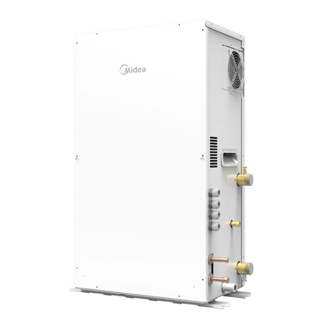
1External Appearance
Figure 1.1: Appearance
2Nomenclature

High Temperature Hydro Module
4 202003
Midea VR High Temperature Hydro Module
3System Schematic
Figure 3.1: Hydraulic box connection method

High Temperature Hydro Module
202003 5
Service Manual
4Specifications
SMK- D140HHN1-3
Power supply
1P~ 220-240V 50/60Hz
Heating Capacity
7/6℃OAT WIT: 40 / WOT: 45 ºC
kW
14
Working range heating
HEAT
/
-20℃~30℃
DHW
/
-20℃~43℃
ambient temperature range
/
/
0℃~40℃
sound pressure level
/
dB
43
water flow rate
nominal
m³/h
2.4
min
m³/h
1.2
max
m³/h
2.9
allowable water pressure
min
MPa
0.1
max
MPa
1.0
Unit dimensions
Height
mm
795
Width
mm
450
Depth
mm
300
Refrigerant pipes connection
Connection type
External Screw Thread
Liquid pipe diameter
mm
Ø 9.52
Gas pipe diameter
mm
Ø 12.7
water pipes connection
Connection type
External Screw Threads
Inlet pipe diameter
mm
25
Outlet pipe diameter
mm
25

High Temperature Hydro Module
6 202003
Midea VR High Temperature Hydro Module
5Electric Control Box Layout

High Temperature Hydro Module
202003 7
Service Manual
5.1 Main PCB
NO.
Port code
Port
code
Content
Port voltage
1
X1X2
CN15
Port for communication with wired controller
0 or 18VDC
2
N1N2
Port for signal of free electricity
0 or 12VDC
3
M1M2
Port for signal of valley electricity
0 or 12VDC
4
PQ
CN17
Port for communication with outdoor unit
2.5-2.7VDC
5
D1D2E
Port for communication with KNX gateway or port for
communication with slave hydro box (group control)
2.5-2.7VDC
6
Y1Y2
CN20
Reserved
\
7
C-PUMP N
Port for circulating pump
220V AC
8
DHW-PUMP
N
Port for DHW pump
220V AC
9
SV3
CN21
Port for three way valve(NC. N for normal close valve,
NO. N for normal open valve)
220V AC
10
N MLSP1
CN22
Port for multiple set point 1
220V AC
11
N MLSP2
Port for multiple set point 2
220V AC
12
AL. N
Reserved
\
13
ST
CN23
Reserved
\

High Temperature Hydro Module
8 202003
Midea VR High Temperature Hydro Module
NO.
Port code
Port
code
Content
Port voltage
13
ST
CN23
Reserved
\
14
FAN
CN24
Pot for fan
220V AC
15
OD
CN6
Port for communication with PC
2.5-2.7VDC
16
FS
CN5
Port for water flow switch
0 or 12VD
17
Twin
CN7
Port for outlet water temperature sensor
0-5V DC(varying)
18
Twout
Port for inlet water temperature sensor
0-5V DC(varying)
19
Ttank
Port for water tank temperature sensor
0-5V DC(varying)
20
T7
CN8
Port for suction pipe temperature sensor
0-5V DC(varying)
21
T2A
Port for R410a circle liquid pipe temperature sensor
0-5V DC(varying)
22
T3
Port for R134a circle liquid pipe temperature sensor
0-5V DC(varying)
23
T7C
CN9
Port for discharge pipe temperature sensor
0-5V DC(varying)
24
H-YL
CN10
Port for high pressure sensor
0-5V DC(varying)
25
L-YL
CN11
Port for low pressure sensor
0-5V DC(varying)
26
H-Pro
CN12
Port for high pressure switch
0 or 5V DC
27
EEV2
CN13
Port for electronic expansion valve 2
0 or 12V DC
28
EEV1
CN14
Port for electronic expansion valve 1
0 or 12V DC
29
L
CN1
Power supply port for main PCB (L)
220V AC
30
N
CN2
Power supply port for main PCB (N)
220V AC
31
L-1
CN4
Power supply port for inverter PCB (L)
220V AC
32
N-1
CN3
Power supply port for inverter PCB (N)
220V AC
33
DEBUG
CN30
Port for IC programming
0-5V DC(varying)
34
DSP1
DSP1
Digital display
\
35
USB
CN25
USB port for IC programming
0-5V DC(varying)
36
SW4
SW4
DIP switch
\

High Temperature Hydro Module
202003 9
Service Manual
Inverter Module
NO.
Port
code
Port
code
Content
Port voltage
1
/
U
Compressor connection port U
380V AC
2
/
V
Compressor connection port V
380V AC
3
/
W
Compressor connection port W
380V AC
4
ACL
CN502
Power supply port for inverter PCB (L)
310V AC
5
ACN
CN501
Power supply port for inverter PCB (N)
310V AC
6
/
CN32
Communication with main PCB
0-5V DC(varying)
7
/
IC315
EEPROM
\

High Temperature Hydro Module
10 202003
Midea VR High Temperature Hydro Module
Installation Cables

High Temperature Hydro Module
202003 11
Service Manual
6Working Range
Heating Mode
DHW Mode
-30
-20
-10
0
10
20
30
40
010 20 30 40 50 60 70 80 90
outdoor temperature /℃
water outlet temperature /℃
continuous heating warm-up operation range
-30
-20
-10
0
10
20
30
40
50
010 20 30 40 50 60 70 80 90
outdoor temperature /℃
water outlet temperature /℃
continuous heating warm-up operation range main cooling operation range

High Temperature Hydro Module
12 202003
Midea VR High Temperature Hydro Module
7Refrigerant Flow Diagrams
ONLY HEATING
Indoor heating + Hydro box
Or only Hydro box

High Temperature Hydro Module
202003 13
Service Manual
MAIN HEATING (Outdoor heat exchanger works as evaporator)
Indoor units in cooling mode +Hydro box
Indoor units in cooling/heating + Hydro box

High Temperature Hydro Module
14 202003
Midea VR High Temperature Hydro Module
MAIN COOLING (Outdoor heat exchanger works as evaporator)
Indoor units in cooling mode +Hydro box
Indoor units in cooling/heating + Hydro box

High Temperature Hydro Module
202003 15
Service Manual
HEAT RECOVERY (Free to provide hot water)
All indoor units in cooling mode + Hydro box

High Temperature Hydro Module
16 202003
Midea VR High Temperature Hydro Module
8High Temperature Hydraulic Module Control Logic
8.1 Start/Stop/ Mode Change

High Temperature Hydro Module
202003 17
Service Manual
8.2 High Temperature Hydraulic Module Control Principle
8.2.1 Compressor Control
The compressor frequency is calculated according to the deviation between Tc and Tcs.
Tc: Measured high pressure saturation temperature
Tcs: Target high pressure saturation temperature
8.2.2 EXV1 Control
EXV1 opening degree is calculated according to the deviation of DSH= T7C-Tc from the DSHS
DSH=T7C-Tc: measured discharge superheat
DSHS: Target discharge superheat
8.2.3 EXV 2 Control
EXV2 open degree is calculated according to the deviation of SC= tc-t2a from SCS.
SC: Measured supercooling from the outlet coper pipe of plate heat exchanger
SCS: Target supercooling from the outlet coper pipe of plate heat exchanger

High Temperature Hydro Module
18 202003
Midea VR High Temperature Hydro Module
8.2.4 Frequency Limit and Protection Control
High Pressure limits the frequency
Other manuals for SMK-D140HHN1-3
1
Table of contents
Other Midea Control Unit manuals
Popular Control Unit manuals by other brands

Parker
Parker ASV5000 Series operating manual

UTC Fire and Security
UTC Fire and Security interlogix VT7420 Installation & operation instructions

Sennheiser
Sennheiser SIS 1019 A 20 Instructions for use

entegris
entegris NT 6300 user guide

Franklin Wireless
Franklin Wireless S600 manual

Data Aire
Data Aire dap4 touch quick start

Trinity Highway
Trinity Highway SST Product Description Assembly Manual

Egcon
Egcon MP3 user manual

HP
HP SIC-4G-LTE-V installation guide

Solid Apollo
Solid Apollo SA-CTRL-InWallRGB-Black product manual

Emerson
Emerson Crosby J Series Installation, operation and maintenance manual

Danfoss
Danfoss PN 16 installation guide