Midland CB-1 User manual

CB-1 CB Radio
Owner’s Manual
CB-1 CB Radio
® Midland Radio Corporation
5900 Parretta Drive
Kansas City, MO 64120
www.MidlandRadio.com

1
www.midlandradio.com
English Français Español
Welcome to the World of Midland Electronics ������������������������������������������������������������������ 2
How to install your Midland mobile CB ����������������������������������������������������������������������������� 2
Installation and Operating Accessories Included�������������������������������������������������������������� 3
Where to Locate your CB Transceiver������������������������������������������������������������������������������ 3
Mechanical Mounting �������������������������������������������������������������������������������������������������������� 3
Power Wiring (negative ground only)�������������������������������������������������������������������������������� 4
Installation of Microphone Hanger ������������������������������������������������������������������������������������ 4
Antenna:
Selection ����������������������������������������������������������������������������������������������������������������������� 4
Installation��������������������������������������������������������������������������������������������������������������������� 5
Tuning ��������������������������������������������������������������������������������������������������������������������������� 5
Range ��������������������������������������������������������������������������������������������������������������������������� 5
Noise ��������������������������������������������������������������������������������������������������������������������������������� 5
Operating Controls ������������������������������������������������������������������������������������������������������������ 6
Back Panel ������������������������������������������������������������������������������������������������������������������������ 7
Transceiver Operation������������������������������������������������������������������������������������������������������� 7
Technical Specications
General ������������������������������������������������������������������������������������������������������������������������� 8
Receiver������������������������������������������������������������������������������������������������������������������������ 8
Transmiter��������������������������������������������������������������������������������������������������������������������� 8
Service ������������������������������������������������������������������������������������������������������������������������������ 9
Limited Warranty ������������������������������������������������������������������������������������������������������������� 10
Other Midland Products �������������������������������������������������������������������������������������������������� 35
Table of Contents

2
www.midlandradio.com
Welcome to the World of Midland Electronics
Congratulations on your purchase of a state-of-the-art mobile CB radio� In the years
ahead, you can expect to realize time and again why Midland holds the front running
position among CB users everywhere� You will come to know that Midland power is
more than just a slogan, but the heading of a long list of benets. As your Midland
CB experience unfolds and grows, we hope you will remember that CB is only one
kind of electronic excellence available under the Midland name�
Your 40 channel CB represents the state of the art in high tech engineering� The unit
incorporates microprocessor controlled PLL circuitry for precise tuning�
How to Install your Midland Mobile CB
This transceiver may be installed in any 12-volt negative ground-system car or truck�
Most current U�S� and foreign vehicles use a negative system, but some older
models and some newer large trucks may have a positive ground�
Check the requirements for your vehicle before you begin installation�
Generally, you have a negative-ground system if the minus ( - ) battery terminal is
connected to the motor block� Contact your dealer in the event you are unable to
determine your vehicle’s polarity system�

3
www.midlandradio.com
English Français Español
Accessories Included
1� Easy removal mounting bracket system�
2� Microphone bracket system�
3� All main-unit and microphone mounting hardware needed for normal installation�
4� Plug-in microphone with coil cord�
5� FCC part 95, Subpart D�
6� Owner’s Manual�
Where to Locate your CB Transceiver
Your new Midland CB is designed to be installed under the dash or vertically on a
console of your vehicle� Safety and convenience are the primary considerations in
deciding exactly where to locate your radio�
Caution: Be sure that the unit is located so that it does not interfere with the driver,
supplemental restraint systems (air bags) or impair access to any controls� Connecting
cables must be routed and secured in such a manner as not to interfere with the
operation of the brake, accelerator or other controls� Interference from either the unit or
connecting cables may contribute to the loss of control of the vehicle�
Mechanical Mounting
1� Heeding the caution, use the mounting bracket as a template for marking the
location of screw holes under the dash� Use an awl, nail or other sharp pointed
object to mark the hole locations�
2� Drill a 1/8” hole for each screw hole in the mounting bracket� Attach the bracket to
the dash with the Phillips head sheet metal screws provided�
Extreme care should be exercised when drilling into the dash to avoid
damage to under-dash electronic ignition, cruise control, instrument and /
or accessory wiring�
3� Position the main unit between the bracket arms in line with the retention knobs� Set
the angle for optimum operating, comfort and accessibility�
4� Tighten the retention knobs�

4
www.midlandradio.com
Power Wiring (negative ground only)
1� If you have not determined whether your vehicle has a negative or positive ground,
do so now� Then disconnect the negative lead from the battery to prevent short cir-
cuits that can occur during wiring� Do not connect this transceiver to positive ground
electrical systems�
2� With negative ground
A� Connect the positive (RED WIRE) the one with in-line fuse holder to either the (a)
fuse block, (b) cigarette lighter, or (c) directly to the positive post on your battery�
Usually, the fuse block is the most convenient connecting point� It is also
possible to connect to the Accessory terminal on the fuse block or ignition switch,
so that your CB automatically goes off when the ignition goes off�
B� Tightly connect the ground (BLACK WIRE) directly to the vehicle’s metal frame� A
good direct metal-to-metal ground is essential for optimum performance�
Installations using the cigarette lighter socket for power require an extra ground
wire from the radio chassis to the vehicle if the radio is not fastened to a
grounded part of the vehicle�
Installation of Microphone Hanger
Mounting holes are provided on the microphone hanger bracket� The bracket can be
attached to the vehicle dash, the holes provided on the left side of the radio, or other
convenient location�
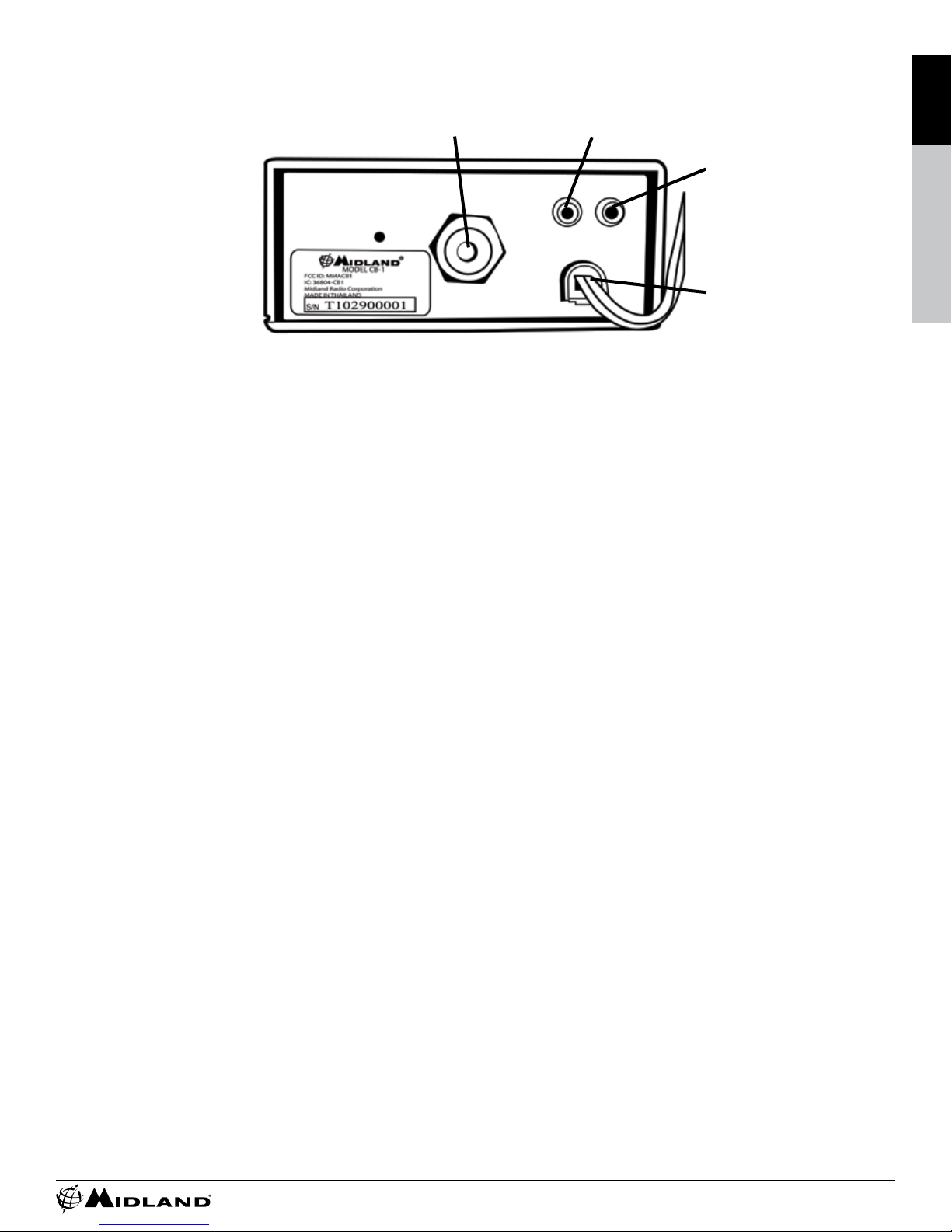
Antenna
You can choose from two types of mobile CB antennas: full-length whip and loaded
whip - and a variety of mounts (depending on where you locate your antenna)� The
dealer who sold you your Midland CB can advise which type is best for you�
*Where you locate your antenna does make a difference.*
Some general rules for antenna location that can aid CB performance:
1� Put your mount as high on the vehicle as possible�
The higher the proportion of antenna length that is above the roof, the better�
2� If possible, mount the antenna in the center of whatever surface you choose�
3� Keep antenna cables away from noise sources, such as the ignition system, gauges,
etc�
4� Make sure you have a solid metal-to-metal ground�
5� Exercise care to prevent cable damage�
Essentially, you have ve location choices: the roof, gutter, rear deck, front cowl or rear
bumper� Where you decide to locate your antenna will determine the type of antenna
you install� Consult your Midland CB dealer for advice and guidance, and measure
your needs against the attributes of the various Midland antenna models they carry�

5
www.midlandradio.com
English Français Español
Antenna Installation
Follow the manufacturer’s installation instructions carefully�
Warning: Never operate your CB radio without attaching an antenna or with a broken
antenna cable� This will result in damage to transmitter circuitry�
Safety notice: The antenna used for this radio must be installed to provide a
separation distance of at least 8 in� (20cm) from all persons and must not be
co-located or operating in conjunction with any other antenna or transmitter�
Tuning Your Antenna
Some antennas are factory tuned� However, performance can usually be improved by
slightly lengthening or shortening the antenna using a Standing Wave Radio (SWR)
meter� For the exact procedures to be used, refer to the antenna manufacturer’s
installation manual�
You can buy an SWR meter separately or have your antenna checked by your Midland
CB Dealer’s service department�
Factors affecting CB range
Essentially, they are the same inuences that optimize or limit AM and FM broadcast
signals�
Terrain: Hills, valleys and buildings naturally interrupt and shorten CB signals� In short,
anything that is between you and the person you want to talk to can shorten your CB
range� You can expect to maintain maximum transmitting/receiving performance in
at, open country.
Weather: You can expect that CB range will be reduced – perhaps drastically – in times
of atmospheric disturbance, such as in a thunderstorm or heavy snow� Sunspots too
are known to adversely affect CB performance�
Noise
A common source of excessive noise is the ignition system� In many vehicles today the
electric fuel pump is another possible source of noise� If you suspect this is true, turn
off the ignition� With the CB in receive mode if the noise is no longer present then
this is the source of the noise� In some cases the noise can be reduced or eliminated
by making sure the CB radio chassis is grounded� This is in addition to the power
cord� In extreme cases, additional grounding of components may be necessary�

6
www.midlandradio.com
Operating Controls
Microphone Connector: Plug in the supplied microphone to this connector�
Received signals will not be heard without the microphone�
ON/OFF Volume Knob: In the off position your transceiver power is off� Turn this
control clockwise to switch on the unit an d adjust the volume�
Channel Buttons: This easy-to-operate control allows changing of CB channels, either
up or down�
Squelch Control: Adjust this control until background noise just disappears� If the
control is adjusted too far clockwise it may cause muting of weaker signals�
Channel Indicator: The LED displays the channel number�
TX LED: Indicator shows the unit is transmitting�
PA/CB Switch: When in PA mode, it causes your voice to operate the optional external
PA speaker� In CB mode, the microphone operates the transmitter�
Channel 9/Normal Switch: Allows you listen to emergency channel 9�
CB/PA
Switch
Normal /
CH9
Switch
TX
Indicator
Digital
Channel
Indicator
Channel
Select Buttons
Locking
Mic
Connector
RF Gain
Knob
Squelch
Knob
ON/OFF
Volume
Knob

7
www.midlandradio.com
English Français Español
Back Panel
Antenna Connector: Connect a standard 50-ohm CB antenna to this connector�
External Speaker Jack: When a speaker is connected to this jack, the internal speaker
is by-passed� All received signals will be heard through the external speaker� The
speaker connected to the “EXT” jack should be rated at 8 ohms and 5 watts�
PA Jack: An optional PA speaker may be attached to your transceiver through the PA
output jack on the back panel� This allows you to communicate with pedestrians or
other vehicles through your CB microphone� The speaker connected to the “PA” jack
should be rated at 8 ohms and 5 watts�
DC 13�8V POWER Cord: Connects to power cord with in line 2 amp fuse�
How To Operate your Transceiver
You should become familiar with the controls and complete the preceding installation
instructions before attempting to operate your CB�
1� Rotate the on/off volume control clockwise to turn the unit on�
2� Adjust the squelch control fully counter-clockwise so noise is heard�
3� Adjust the volume for a normal listening level�
4� Rotate the squelch control until the noise just disappears�
5� Select the desired channel�
6� To transmit, press the PTT bar on the side of the microphone� Hold the microphone
2 to 3 inches from your mouth and speak in a normal voice�
7� To receive, simply release the PTT bar�
Warning: Do not attempt to make any internal adjustments� Internal adjustments
and/or modications can lead to illegal operation as dened by the FCC rules and
regulations, Part 95. They must be made only by qualied technical personnel.
Illegal operation can lead to serious consequences�
Antenna
Connector
PA
Jack EXT
Speaker
Jack
13�8VDC
Power
Cord

8
www.midlandradio.com
Technical Specications
General
Frequency Range�������������������������������������������������������������������������������� 26�965-27�405 MHz
Channels ������������������������������������������������������������������������������������������������������������������������� 40
Modulation Type�������������������������������������������������������������������������������������������������������������AM
Antenna Impedance�����������������������������������������������������������������������������������������������������50 Ω
Loudspeaker ������������������������������������������������������������������������������������������������������������������8 Ω
Microphone������������������������������������������������������������������������������������������������� 1000 ٠Electret
Power Supply ����������������������������������������������������������������������������13�8 VDC negative ground
Size ������������������������������������������������������������������������������ 4-3/8” (W) x 4-3/4” (D) x 1-7/8” (H)
Unit Weight����������������������������������������������������������������������������������������������������������1 lb� 10 oz
Receiver (CB, 26�965-27�405 MHz,)
Sensitivity at 10dB S/N����������������������������������������������������������������������������������������������0�7 µV
Selectivity ���������������������������������������������������������������������������������������������������� 45dB + 10 kHz
Squelch Range�������������������������������������������������������������������������������������������0�5 µV - 500 µV
Audio Output Power�������������������������������������������������������������2.0 W @ 8 ٠(10% distortion)
Distortion at 1000 µV������������������������������������������������������������������������������������������������������ 3%
Audio Frequency response �����������������������������������������������������������������������������400-2400 Hz
Intermediate Frequency ������������������������������������������������������1st: 10�695 MHz 2nd: 455 kHz
Spurious Response��������������������������������������������������������������������������������������������������> 40dB
Transmitter
RF Output Power �������������������������������������������������������������������������������������������������������4�0 W
Frequency Tolerance����������������������������������������������������������������������������������������������� 0.005%
Harmonic Suppression��������������������������������������������������������������������������������������������> 60 dB
Modulation��������������������������������������������������������������������������������������������������AM 90% (± 5%)

9
www.midlandradio.com
English Français Español
Service
If it ever becomes necessary to return your unit for service:
Pack the unit in its original box and packing, improper packing may result in damage
during shipment� Be sure to remove the microphone from the radio before packing�
Include a full description of any problems� Include a daytime telephone number in the
event we need more information�
You do not need to return accessory items (brackets, screws, power cord, antenna,
etc�) unless they may be directly related to the problem�
Include a photocopy of the bill of sale or other proof of purchase showing the date of
sale (credit card statements are not acceptable)� This information must be included
before warranty service can be considered�
A at rate charge of $45 will apply to radios not covered by the Warranty. Master Card,
Visa, Cashier’s Check or Money Order will be accepted for payment only� Personal
checks will not be accepted and will delay the repair of your radio until we receive
payment by approved methods�
Midland Radio Corporation
Hereby certies that this unit has
been designed, manufactured,
FCC type accepted and certied
in accordance with Part 95 and
Part 15, Subpart C of the current
FCC rules and regulations as of
the date of manufacture�

Limited Warranty
Midland Radio Corporation will repair or replace, at its option without charge this model
CB1 Citizens Band transceiver that fails due to a defect in material or workmanship
within Three years following the initial consumer purchase�
This warranty does not include any accessories, which may be a part of or included
with the warranted product, or the cost of labor for removal or re-installation of the
product in a vehicle or other mounting�
Performance of any obligation under this warranty may be obtained by returning the
warranted product, freight prepaid, along with proof of purchase date, to Midland
Radio Corporation , Warranty Service Department, 5900 Parretta Drive, Kansas City,
Missouri 64120, or to any “Midland Authorized Warranty Service Station,” or to the
place of purchase (if a participating dealer). This warranty gives you specic legal
rights, and you may also have other rights which vary from state to state�
Note: The above warranty applies only to merchandise purchased in the United States
of America or any of the territories or possessions thereof, or from a U�S� Military
exchange� For warranty coverage on merchandise purchased elsewhere, consult the
supplemental warranty information included with this product or ask your dealer�
MIDLAND RADIO CORPORATION
5900 Parretta Drive
Kansas City, MO 64120
Phone 816-241-8500
E-mail: mail@midlandradio�com
www�midlandradio�com
Printed in Thailand


13
www.midlandradio.com
English Français Español
Bienvenue dans le monde de Midland Electronique������������������������������������������������������� 14
Comment installer votre BP portatif Midland������������������������������������������������������������������� 14
Installation et Accessoires de Fonctionnement compris������������������������������������������������� 15
Comment repérer votre émetteur-récepteur BP ������������������������������������������������������������� 15
Fixation Mécanique��������������������������������������������������������������������������������������������������������� 15
Câblage d’alimentation (mise à la terre négative seulement)����������������������������������������� 16
Installation du porte micro����������������������������������������������������������������������������������������������� 16
Antenne:
Sélection �������������������������������������������������������������������������������������������������������������������������������16
Installation������������������������������������������������������������������������������������������������������������������� 17
Syntonisation �������������������������������������������������������������������������������������������������������������� 17
Portée ������������������������������������������������������������������������������������������������������������������������� 17
Bruit ��������������������������������������������������������������������������������������������������������������������������������� 17
Commandes de fonctionnement������������������������������������������������������������������������������������� 19
Panneau arrière �������������������������������������������������������������������������������������������������������������� 19
Utilisation de l’emetteur-récepteur ���������������������������������������������������������������������������������� 19
Spécications techniques
Spécications générales��������������������������������������������������������������������������������������������� 20
Récepteur ������������������������������������������������������������������������������������������������������������������� 20
Émetteur ��������������������������������������������������������������������������������������������������������������������� 20
Service ���������������������������������������������������������������������������������������������������������������������������� 21
Garantie limitée ��������������������������������������������������������������������������������������������������������������� 22
Autres produits Midland �������������������������������������������������������������������������������������������������� 35
Table des matières

14
www.midlandradio.com
Bienvenue dans le monde de Midland Electronics
Félicitations Vous avez acheté radio BP portative de pointe� Dans les années à venir,
vous pouvez vous comprendrez rapidement et avec certitude pourquoi Midland est
le choix préféré des utilisateurs de BP à l’échelle mondiale�� Vous réaliserez que
Midland Power est plus qu’un slogan� Cela représente une longue liste d’avantages
démontrés et prouvés� Au fur et à mesure que vous acquerrez de l’expérience avec
votre BP Midland, souvenez vous toujours que Midland offre de nombreux autres
excellents produits électroniques�
Votre BP à 40 canaux représente la ne pointe de l’ingénierie de haute technologie. Cet
appareil intègre un circuit PLL contrôlé par un microprocesseur pour un réglage précis�
Comment installer votre BP portatif Midland
Cet émetteur-récepteur peut être installé dans n’importe quel système de mise à la
terre négatif de 12-volt d’une voiture ou d’camion� La plupart des véhicules améric-
ains ou étrangers utilisent un système négatif, mais certains vieux modèles et cer-
tains nouveaux camions de plus grande capacité peuvent avoir un système de mise
à la terre positif�
Vériez les exigences de votre véhicule avant de commencer l’installation.
Généralement, vous avez un système de mise à la terre négatif si la borne de la bat-
terie négative (-) est connectée au bloc-moteur� Communiquez avec votre conces-
sionnaire si vous êtes incapable de déterminer la polarité du système de votre véhi-
cule�

15
www.midlandradio.com
English Français Español
Accessoires Compris
1. Système de support de xation amovible.
2. Système de xation du microphone.
3. Matériel de xation nécessaire à l’installation de l’unité principale et du microphone.
4. Microphone enchable avec cordon enroulé.
5� FCC section 95, sous section D�
6� Guide de l’utilisateur�
Comment repérer votre émetteur-récepteur BP
Votre nouveau BP Midland est conçu pour être installé sous le tableau de bord ou
verticalement sur une console de votre véhicule� La sécurité et la commodité sont les
considérations premières pour décider de l’emplacement de votre radio�
Avertissement : Assurez vous que l’appareil est situé de façon à ne pas nuire au le
conducteur, aux dispositifs de retenue supplémentaires (sacs gonables) ou empêcher
l’accès aux contrôles� Les câbles connectés doivent être assemblés et sécurisés de
manière à ne pas interférer avec l’utilisation des freins, de l’accélérateur ou des autres
contrôles� L’interférence de l’appareil ou des câbles connectés peut contribuer à la
perte de contrôle du véhicule�
Fixation mécanique
1. En respectant l’avertissement, utilisez le support de xation comme un modèle pour
marquer l’emplacement des trous de vis sous le tableau de bord� Utilisez un
poinçon, un clou ou un autre objet pointu pour marquer la position des trous�
2. Perforez un trou de 1/8 pouce pour chaque trou de vis dans le support de xation.
Fixez le support au tableau de bord avec les vis tarauds à tête Phillips fournies�
Un soin extrême devrait être exercé lorsque vous perforez dans le
tableau de bord pour éviter d’endommager à l’allumage électronique, le
régulateur de vitesse automatique, les instruments et/ou le câblage des
accessoires, situés sous le tableau de bord�
3� Positionnez l’appareil principal entre les bras du support et alignez-le avec les bou-
tons de retenue�� Fixez l’angle pour un confort et une accessibilité d’utilisation opti-
male�
4� Serrez les boutons de retenue�

16
www.midlandradio.com
Câblage d’alimentation (mise à la terre négative seulement)
1� Si vous n’avez pas déterminé la polarité de la mise à la terre de votre véhicule, faîtes-le
maintenant� Ensuite, débranchez la borne négative de la batterie pour éviter des courts-
circuits durant le câblage� Ne branchez pas cet émetteur-récepteur à des systèmes
électriques de mise à la terre positive�
2� Avec une mise à la terre négative
A� Branchez le câble le positif (FIL ROUGE), celui avec le porte fusible en ligne, soit (a) au
boîtier à fusibles, (b) à l’allume-cigare, ou (c) directement à la borne de batterie posi-
tive� Habituellement, le boîtier à fusibles est le point de connexion le plus conven able�
Il est aussi possible de le brancher à la borne pour accessoires du boîtier à fusibles ou
l’allumage, pour que votre BP s’éteigne automatiquement lorsque l’allumage est éteint�
B� Branchez fermement le câble de négative (FIL NOIR) directement au châssis métal-
lique du véhicule� Une bonne mise à la terre négative métal à métal est nécessaire
pour une performance optimale� L’ installations utilisant l’allume-cigare comme source
d’alimentation nécessitet un câble de mise à la terre négative additionnel du châssis
de la radio au véhicule si la radio n’est pas rattachée à une partie du véhicule mise à la
terre�
Installation du porte micro
Des trous de xation sont fournis sur le support du porte micro. Le support peut être
xé au tableau de bord du véhicule, aux trous fournis sur le côté gauche de la radio,
ou à un autre endroit convenable�
Antenne
Vous avez le choix entre deux types d’antennes BP portatives - antenne fouet pleine lon-
gueur et antenne fouet chargée - et une variété de xations (selon l’emplacement de
votre antenne)� Le concessionnaire qui vous a vendu votre BP Midland peut vous con-
seiller à savoir quel type vous convient le mieux�
*L’emplacement de votre antenne est important*
Quelques règles générales sur l’emplacement de l’antenne pour aider la performance de la
BP :
1. Installez votre xation le plus haut possible sur le véhicule.
Plus la proportion de l’antenne est au-dessus du toit, le mieux�
2. Si possible, xez l’antenne au centre de la surface que vous choisissez,
3� Éloignez les câbles de l’antenne des sources de bruit, comme le système d’allumage,
les indicateurs etc�
4� Assurez vous d’avoir une mise à terre solide métal à métal�
5� Soyez prudent pour éviter d’endommager les câbles�
Essentiellement, vous avez le choix entre cinq emplacements : le toit, le crochet de jante,
le coffre arrière, l’auvent avant ou le pare-chocs arrière� Le choix de l’emplacement dé-
terminer le type d’antenne à installer� Consultez votre détaillant BP Midland pour des
conseils, et déterminez vos besoins selon les attributs des différents modèles d’antennes
Midland offerts�

17
www.midlandradio.com
English Français Español
Installation de l’Antenne
Suivez soigneusement les instructions d’installation du fabricant�
Avertissement : N’utilisez jamais votre radio BP sans antenne ou avec un câble d’antenne
brisé� Cela pourrait endommager les circuits de l’émetteur récepteur�
Avis de sécurité : L’antenne utilisée pour cette radio doit être installée de manière à fournir
une distance de séparation d’au moins 8 pouces (20 cm) de toute personne et ne doit
pas être située ou utilisée en conjonction avec d’autres antennes ou émetteurs-ré-
cepteurs�
Syntoniser votre antenne
Certaines antennes sont syntonisées en usine� Cependant, la performance peut habi-
tuellement être améliorée en allongeant ou réduisant légèrement l’antenne en util-
isant un rapport d’onde stationnaire� Pour les procédures exactes à respecter, ref-
erez vous au guide d’installation de l’antenne du fabricant�
Vous pouvez acheter un rapport d’onde stationnaire séparément ou demander au
département de service de votre détaillant BP Midland de vérier votre antenne.
Facteurs affectant la portée de votre BP
Essentiellement, ce sont les mêmes inuences qui optimisent ou limitent les signaux
de diffusion AM et FM�
Terrain : Les montagnes, vallées, et bâtiments interrompent et diminuent naturellement
les signaux BP� En somme, tout ce qui se situe entre vous et la personne à qui vous
voulez parler peut diminuer la portée de votre BP� Vous pouvez vous attendre à
maintenir la performance maximale de transmission/réception sur des terrains plats
et ouverts�
Température : Vous pouvez vous attendre à ce que la portée de la BP soit réduite -
peut-être drastiquement - en temps de perturbations atmosphériques, comme un
orage ou de la forte neige� Les taches solaires sont aussi réputées d’affecter néga-
tivement la performance de la BP�
Bruit
Une source habituelle de bruit excessif est l’allumage� Aujourd’hui, dans plusieurs vé-
hicules, la pompe à carburant à commande électrique est une autre source possible
de bruit� Si vous soupçonnez que c’est le cas, fermez l’allumage� Si le bruit n’est
plus présent avec la BP en mode réception, c’est une source de bruit� Dans certains
cas, le bruit peut être réduit ou éliminé en s’assurant que le châssis de la radio BP
est mis à la terre en plus du cordon d’alimentation� Dans des cas extrêmes, une
mise à la terre additionnelle des composants peut être nécessaire�

18
www.midlandradio.com
Commandes de fonctionnement
Connecteur microphone : Connectez le microphone fourni à ce connecteur� Les
signaux reçus ne seront pas entendus sans le microphone�
Commande de contrôle du volume : À la position hors tension, votre émetteur-ré-
cepteur est fermé� Tournez la commande vers la droite pour activer l’appareil et
ajuster le volume�
Touches de sélection des canaux : Ce contrôle simple à utiliser permet de changer de
chaînes de bande CB, vers une fréquence supérieure ou inférieure�
Silencieux : Ajustez cette commande jusqu’à ce que le bruit de fond disparaisse� Si la
commande est ajustée trop loin vers la droite, ça peut les signaux plus faibles peu-
vent être mis en sourdine�
Indicateur numérique des canaux : Le voyant DEL afche le numéro du canal.
Voyant TX : Le voyant indique que l’appareil est en cours de transmission�
Commutateur mode normal et 9 canaux : Vous permet d’écouter la chaîne d’urgence 9�
Commutateur PA/BP : En mode amplicateur de puissance, votre voix active le haut-
parleur PA externe optionnel� En mode BP, le microphone active l’émetteur
Commutateur
BP/PA
Commutateur
mode normal
et 9 canaux
Voyant TX Indicateur
numérique
des canaux
Touches de
sélection
des canaux
Connecteur
microphone
Commande
de gain RF Silencieux Commande
de contrôle
du volume

19
www.midlandradio.com
English Français Español
Panneau Arrière
Connecteur antenne : Connectez une antenne BP standard 50-ohm BP à ce connecteur
Prise d’amplicateur de puissance : Un haut-parleur optionnel d’amplicateur de puissance
peut être xé à votre émetteur par la prise de sortie d’amplicateur de puissance sur le
panneau arrière� Cela vous permet de communiquer avec des piétons ou d’autres vé-
hicules avec votre microphone BP� Le haut-parleur connecté à la prise PA devrait être
régléà 8 ohms et 5 watts�
Prise pour haut-parleur externe : Lorsqu’un haut parleur est connecté à cette prise, le haut
parleur interne est contourné� Tous les signaux reçus seront entendus par le haut-parleur
externe� Le haut-parleur connecté à la prise EXT devrait être réglé à 8 ohms et 5 watts�
Cordon d’Alimentation CC 13�8V : Se connecte au cordon d’alimentation avec un
fusible en ligne de 2 A�
Utilisation de l’emetteur-récepteur
Vous devriez vous familiariser avec les commandes et compléter l’installation précé-
dente avant d’essayer de faire fonctionner votre BP�
1� Tournez la commande marche/arrêt u volume vers la droite pour activer l’appareil�
2� Ajustez la commande silencieux vers la gauche pour entendre du bruit�
3� Ajustez le volume à un niveau normal d’écoute�
4� Tournez la commande silencieux jusqu’à ce que le bruit disparaisse�
5� Choisissez le canal désiré�
6� Pour transmettre, appuyez sur la barre PPT sur le côté du microphone� Tenez le mi-
cro à une distance de 2 à 3 pouces de vos lèvres et parlez d’une voix normale�
7� Pour recevoir, lâchez simplement la barre PPT�
Avertissement : Ne tentez pas de faire des ajustements internes� Des ajustements et/
ou modications internes peuvent causer une utilisation illégale telle que dénie par
les règles et réglementations de la FCC, section 95� Ils doivent être effectués seule-
ment par du personnel technique qualié. Une utilisation illégale peut entraîner des
conséquences sérieuses�
Connecteur
antenne
Prise
d’ amplicateur
de puissance
Prise Pour
haut-parleur
externe
Cordon
d’ Alimentation
CC 13�8V
Table of contents
Languages:
Other Midland Radio manuals

Midland
Midland D-200 User manual

Midland
Midland G7XT Manual

Midland
Midland ER310 User manual

Midland
Midland 5001z User manual

Midland
Midland 1001LWXA User manual

Midland
Midland XT511 Manual

Midland
Midland G18 Manual

Midland
Midland 70-1526A User manual

Midland
Midland HH50 User manual

Midland
Midland M-Mini Manual

Midland
Midland PRO902 User manual

Midland
Midland 210 DS User manual

Midland
Midland DBR2500 User manual

Midland
Midland 71-506-10D User manual

Midland
Midland Alan 78 Plus Multi B User manual

Midland
Midland Alan 255ESP D80 User manual

Midland
Midland SpeakEasy Ultra User manual

Midland
Midland 77321 Manual

Midland
Midland 75-822 User manual

Midland
Midland BR180 User manual