manuals.online logo
Brands
  1. Home
  2. •
  3. Brands
  4. •
  5. Cree
  6. •
  7. Lighting Equipment
  8. •
  9. Cree LXB Series User manual

Cree LXB Series User manual

LXB Series
LED Linear High Bay with Emergency Driver
1 of 4 LPN00599X0002A0_A
INSTALLATION INSTRUCTIONS
INSTRUCTIONS D’INSTALLATION
IMPORTANT SAFEGUARDS
When using electrical equipment, basic safety precautions should
always be followed including the following:
READ AND FOLLOW ALL SAFETY
INSTRUCTIONS
1. DANGER- Risk of shock- Disconnect power before installation.
DANGER - RISQUE DE CHOC - COUPER L’ALIMENTATION
AVANT L’INSTALLATION
2. CAUTION – Installation and servicing should be performed by
qualied personnel only. De-energize before opening.
ATTENTION – L’installation et l’entretien doivent être effectués
par du personnel qualié seulement. Mettre hors tension avant
l’ouverture
3. To reduce the risk of electric shock, disconnect both standard and emergency power supplies and converter connector of the
emergency driver before servicing.
Pour réduire le risque de décharge électrique, vous devez déconnecter à la fois le disjoncteur divisionnaire ou les fusibles et les
alimentations d’urgence avant l’entretien.
4. Do not use outdoors.
Ne pas utiliser à l’extérieur.
5. Do not let power supply cords touch hot surfaces.
Ne laissez pas les cordons d’alimentation toucher les surfaces chaudes.
6. Do not mount near gas or electric heaters.
Ne montez PAS près des appareils de chauffage de gaz ou électriques.
7. Do not use this equipment for other than intended use.
8. Equipment should be mounted in locations and heights where it will not readily be subjected to tampering by unauthorized
personnel.
L’équipement doit être monté dans des endroits et à des hauteurs où il ne sera pas soumis à des altérations par des personnes
non autorisées.
9. The use of accessory equipment not recommended by the manufacturer may cause an unsafe condition.
L’utilisation d’accessoires non recommandés par le fabricant peut causer une situation dangereuse.
10. Max. mounting height: 20 ft.
Hauteur de montage max.: 10.
11. Do not handle energized module with wet hands or when standing on wet or damp surfaces, or in water.
SAVE THESE INSTRUCTIONS FOR FUTURE REFERENCE
NOTES:
• DO NOT handle the Luminaire by the light bars. See Figure 7 on the back page for required handling locations.
• Products with the -EB suffix are provided with a factory-installed emergency lighting LED battery pack and are eligible to serve as part of a
facility’s emergency lighting system in accordance with ANSI/NFPA 101 and Article 700 of ANSI/NFPA 70.
• When mounted at or below 20ft, -EB products will provide the required 1 foot-candle of illuminance on the floor.
Max Rated Ambient
Fixture Size Suspended 18" Surface Mount
18L 55C 45°C
24L 55C 45°C
2 of 4 LPN00599X0002A0_A
CHAIN SUSPENSION
STEP 1:
Insert the supplied wire hangers through the
holes on the top of the luminaire as shown
in Figure 1. To prevent wire hangers from
disconnecting from the Luminaire, pinch the
ends of the wire hangers shut.
STEP 2:
Attach customer supplied chain, hook, or
aircraft cable to each of the wire hangers
STEP 3:
Attach opposite ends to the mounting surface.
Make sure mounting surface, customer
supplied suspension method, and hardware
can support the weight of the luminaire.
STEP 4:
Remove the wiring access cover from the top
of luminaire by loosening screw and slide
the cover towards screw hole and then lift to
remove. Remove necessary knockout(s) in
wiring cover. See Figure 2.
Cord Kit:
Insert leads of cord through hole in wiring
access cover and snap strain relief into
cover
Conduit:
Insert leads from conduit through hole
in wiring access cover. Secure conduit to
cover with conduit nut on opposite side of
the cover.
STEP 5:
Make wiring connections per the Electrical
Connections section.
STEP 6:
Replace wiring access cover by reversing
sequence used to remove it. Make sure both
ends of cover are engaged with the top of the
wiring chamber. Secure cover in place using
screw removed in Step 4.
PENDANT INSTALLATION
STEP 1:
Mount the Pendant Mount Box to the mounting
location by attaching the customer supplied ½”
threaded suspension conduit, along with the 2
customer supplied locknuts (one for the inside
of the Pendant Mount Box and one for the
outside) to the Pendant Mount Box.
STEP 2:
Remove the Wire Access Cover from the top
of the luminaire by loosening the screw and
slide the cover towards screw hole and then
lift to remove. Wire Access Cover is located in
the center of the luminaire directly below the
pendant mount accessory. See Figure 3.
STEP 3:
Discard the wire access cover. Pull input lead
wires out of the Driver Housing in order to
make splices inside the Pendant Mount Box.
Cord Kit:
Insert leads of cord through hole in wiring
access cover and snap strain relief into
cover
Conduit:
Insert leads from conduit through hole
in wiring access cover. Secure conduit to
cover with conduit nut on opposite side of
the cover.
NOTE: If connecting to customer supplied
lead wires that are routed through the
pendant, the Driver Housing Cover can be
removed and wires routed into the Pendant
Mount Box
STEP 4:
Attach the luminaire to the Pendant Mount Box
as shown in Figure 4.
3
Wire Access Cover
Driver Housing
TO INSTALL:
1
Wire Hangers
2
Slotted Holes
Wiring
Access Cover
Screw Hole
Pendant Mount Box
Hooks
Pendant Mount Box
4
3 of 4 LPN00599X0002A0_A
STEP 5:
Route customer supplied input leads
through pendant or attach cord or conduit to
knockout(s) in the side of the Pendant Mount
Box.
STEP 6:
Make wiring connections per the Electrical
Connections section.
STEP 7:
Tilt Pendant Mount Box into place until screw
hole on Pendant Mount Box are lined up with
screw holes on luminaire. Secure Pendant
Mount Box using two supplied screws. See
Figure 5.
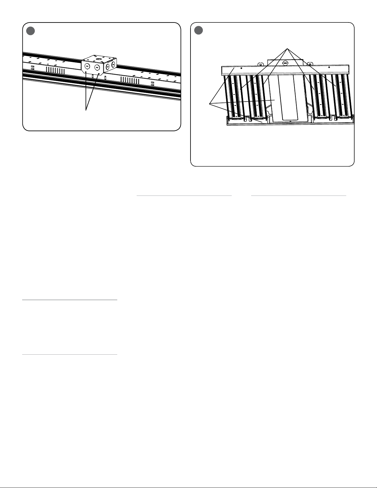
WIRE GUARD INSTALLATION
STEP 1:
Bring the wire guard up to the luminaire
and secure to the luminaire by inserting (2)
supplied screws into each side of the luminaire
as shown in Figure 7 on last page.
LENS INSTALLATION
STEP 1:
Remove transparent film off of lens and discard
prior to installation.
STEP 2:
Install the lens over the LEDs by snapping the
lens into place. See Figure 8 on last page.
STEP 3:
Repeat steps 1 and 2 and install a lens over
each light bar.
NOTE: To clean, release lens from the top of
the light bar extrusion and wipe clean with a
damp cloth
FCC NOTICE
CAUTION: Changes or modifications not
expressly approved could void your authority to
use this equipment.
This device complies with part 15 of the FCC
Rules. Operation is subject to the following
two conditions: (1) This device may not cause
harmful interference, and (2) this device must
accept any interference received, including
interference that may cause undesired
operation.
This equipment has been tested and found
to comply with the limits for a Class A
digital device, pursuant to part 15 of the FCC
Rules. These limits are designed to provide
reasonable protection against harmful
interference when the equipment is operated
in a commercial environment. This equipment
generates, uses, and can radiate radio
frequency energy and, if not installed and used
in accordance with the instruction manual,
may cause harmful interference to radio
communications. Operation of this equipment
in a residential area is likely to cause harmful
interference in which case the user will be
required to correct the interference at his own
expense.
CAN ICES-005 (A)/NMB-005 (A)
EMERGENCY DRIVER CHECK
NOTE: For short-term testing of the emergency
function, the battery must be charged for at
least one hour. The emergency driver must be
charged for at least 24 hours before conducting
a long-term test.
STEP 1:
When AC power is applied, the charging
indicator light is illuminated, indicating the
battery is being charged. When power fails,
the emergency driver automatically switches
to emergency power, operating the LED array.
When AC power is restored, the emergency
driver returns to the charging mode.
STEP 2:
Although no routine maintenance is required
to keep the emergency driver functional, it
should be checked periodically to ensure
that it is working. The following schedule is
recommended:
• Visually inspect the charging indicator
light monthly. It should be illuminated.
• Test the emergency operation of the
fixture at 30-day intervals for a minimum
of 30 seconds. When the test switch
is depressed, the LED array should
operate.
• Conduct a 90-minute discharge test once
a year. The LED array should operate for
at least 90 minutes.
If the luminaire fails any of these checks,
consult service personnel.
REFER ANY SERVICING INDICATED BY THESE
CHECKS TO QUALIFIED PERSONNEL
EMERGENCY DRIVER AND AC DRIVER MUST
BE FED FROM THE SAME BRANCH CIRCUIT
6
Good For
Handling
Bad For Handling
Screw Holes
5
4 of 4 LPN00599X0002A0_A
www.lighting.cree.com
© 2018 Cree, Inc. All rights reserved. For informational purposes only. Content is subject to change.
See http://lighting.cree.com/warranty for warranty and specifications. Cree® is a registered trademark, and the Cree logo is a
trademark of Cree, Inc. NEMA® is a registered trademark of the National Electrical Manufacturers Association.
ELECTRICAL CONNECTIONS
NOTE: The emergency driver must be fed from
the same branch as the AC Driver.
STEP 1:
Using customer supplied 90°C minimum rated wire
connectors, make the following electrical connections:
a. Connect the black luminaire lead to the
unswitched voltage supply lead.
b. Connect the white/red luminaire lead to
the switched supply switched.
c. Connect white luminaire lead to the neutral supply lead.
d. Connect ground bare or green/yellow lead to the
incoming ground lead from the conduit or screw the
green ground lead to the existing troffer pan if the safety
ground is made through the pan on the existing troffer.
e. If 0/1-10V Dimming is used, connect the violet lead
to the supply positive dimming lead. If dimming is
not being used ensure to cap off the violet lead.
f. If 0/1-10V Dimming is used, connect the gray lead
to the supply negative dimming lead. If dimming is
not being used ensure to cap off the gray lead.
STEP 2:
Locate the two red leads in the junction box and connect them
using customer supplied connector.
WHITE
DIM (-) GREY
DIM (+) VIOLET VIOLET
GREY
SUPPLY WIRING
(DIMMING OPTIONAL)
LUMINAIRE
GROUND
BARE OR
GREEN/YELLOW
WHITE/RED
SWITCHED HOT
BLACK
UNSWITCHED HOT
** NOTE: DO NOT mate leads until installation
is complete and AC power is supplied
**RED
**RED
WHITE
NEUTRAL
87
Lens
Wire guard
Insert screws

Other Cree Lighting Equipment manuals

Cree C-LITE C-WP-A-FCT3 Series User manual

Cree

Cree C-LITE C-WP-A-FCT3 Series User manual

Cree C-AR Series User manual

Cree

Cree C-AR Series User manual

Cree OSQ HO Series User manual

Cree

Cree OSQ HO Series User manual

Cree OSQ Series User manual

Cree

Cree OSQ Series User manual

Cree OSQ Series User manual

Cree

Cree OSQ Series User manual

Cree CR24 UPKIT User manual

Cree

Cree CR24 UPKIT User manual

Cree XLamp MH Series User manual

Cree

Cree XLamp MH Series User manual

Cree Essentia S-DL4-EB User manual

Cree

Cree Essentia S-DL4-EB User manual

Cree OSQ Series User manual

Cree

Cree OSQ Series User manual

Cree ESSENTIA AE Series User manual

Cree

Cree ESSENTIA AE Series User manual

Cree XLamp XR Series User manual

Cree

Cree XLamp XR Series User manual

Cree OSQ Series User manual

Cree

Cree OSQ Series User manual

Cree LQ6 Series User manual

Cree

Cree LQ6 Series User manual

Cree Link With SmartCast Technology User manual

Cree

Cree Link With SmartCast Technology User manual

Cree SmartCast FLEX Series User manual

Cree

Cree SmartCast FLEX Series User manual

Cree CR Series User manual

Cree

Cree CR Series User manual

Cree TDS Series User manual

Cree

Cree TDS Series User manual

Cree OSQ Series User manual

Cree

Cree OSQ Series User manual

Cree ZR Series User manual

Cree

Cree ZR Series User manual

Cree TRDL6 Series User manual

Cree

Cree TRDL6 Series User manual

Cree ESSENTIA S-CT-FB-25L User manual

Cree

Cree ESSENTIA S-CT-FB-25L User manual

Cree LS8 User manual

Cree

Cree LS8 User manual

Cree CXB Series User manual

Cree

Cree CXB Series User manual

Cree CPY Series User manual

Cree

Cree CPY Series User manual

Popular Lighting Equipment manuals by other brands

LumX LED B-180 instruction manual

LumX

LumX LED B-180 instruction manual

EuroLite LED DMX Tube 1m RGB IP20 user manual

EuroLite

EuroLite LED DMX Tube 1m RGB IP20 user manual

Aseko ASIN AQUA Home VS user manual

Aseko

Aseko ASIN AQUA Home VS user manual

Stahl 6470/2 Series manual

Stahl

Stahl 6470/2 Series manual

RL R55382102 manual

RL

RL R55382102 manual

American DJ Mystic User instructions

American DJ

American DJ Mystic User instructions

thomann Stairville PAR 64 user manual

thomann

thomann Stairville PAR 64 user manual

LED Lighting SPOT 300 FRE user manual

LED Lighting

LED Lighting SPOT 300 FRE user manual

TRACE-LITE TLED-XPF installation instructions

TRACE-LITE

TRACE-LITE TLED-XPF installation instructions

Meteor Stem Dext 2.0 Series installation instructions

Meteor

Meteor Stem Dext 2.0 Series installation instructions

Titanium TT-U-UX8 manual

Titanium

Titanium TT-U-UX8 manual

Armacost Lighting RibbonFlex PRO manual

Armacost Lighting

Armacost Lighting RibbonFlex PRO manual

GAME OF BRICKS Millennium Falcon 75192 instruction manual

GAME OF BRICKS

GAME OF BRICKS Millennium Falcon 75192 instruction manual

Ledj LEDJ283A user manual

Ledj

Ledj LEDJ283A user manual

Utilitech CMG-NYC-M3 installation instructions

Utilitech

Utilitech CMG-NYC-M3 installation instructions

Lake Lite LL-SPL-PAG-WBA quick start guide

Lake Lite

Lake Lite LL-SPL-PAG-WBA quick start guide

Nitecore T4K user manual

Nitecore

Nitecore T4K user manual

SCANGRIP NOVA 4 CAS manual

SCANGRIP

SCANGRIP NOVA 4 CAS manual

manuals.online logo
manuals.online logoBrands
  • About & Mission
  • Contact us
  • Privacy Policy
  • Terms and Conditions

Copyright 2025 Manuals.Online. All Rights Reserved.